EP1807253B1 - Method to produce stretchable products - Google Patents
Method to produce stretchable products Download PDFInfo
- Publication number
- EP1807253B1 EP1807253B1 EP05857369.2A EP05857369A EP1807253B1 EP 1807253 B1 EP1807253 B1 EP 1807253B1 EP 05857369 A EP05857369 A EP 05857369A EP 1807253 B1 EP1807253 B1 EP 1807253B1
- Authority
- EP
- European Patent Office
- Prior art keywords
- former
- workpiece
- wall
- product material
- sprayer
- Prior art date
- Legal status (The legal status is an assumption and is not a legal conclusion. Google has not performed a legal analysis and makes no representation as to the accuracy of the status listed.)
- Expired - Lifetime
Links
Images


Classifications
-
- B—PERFORMING OPERATIONS; TRANSPORTING
- B29—WORKING OF PLASTICS; WORKING OF SUBSTANCES IN A PLASTIC STATE IN GENERAL
- B29C—SHAPING OR JOINING OF PLASTICS; SHAPING OF MATERIAL IN A PLASTIC STATE, NOT OTHERWISE PROVIDED FOR; AFTER-TREATMENT OF THE SHAPED PRODUCTS, e.g. REPAIRING
- B29C41/00—Shaping by coating a mould, core or other substrate, i.e. by depositing material and stripping-off the shaped article; Apparatus therefor
- B29C41/34—Component parts, details or accessories; Auxiliary operations
- B29C41/42—Removing articles from moulds, cores or other substrates
-
- B—PERFORMING OPERATIONS; TRANSPORTING
- B29—WORKING OF PLASTICS; WORKING OF SUBSTANCES IN A PLASTIC STATE IN GENERAL
- B29C—SHAPING OR JOINING OF PLASTICS; SHAPING OF MATERIAL IN A PLASTIC STATE, NOT OTHERWISE PROVIDED FOR; AFTER-TREATMENT OF THE SHAPED PRODUCTS, e.g. REPAIRING
- B29C33/00—Moulds or cores; Details thereof or accessories therefor
- B29C33/44—Moulds or cores; Details thereof or accessories therefor with means for, or specially constructed to facilitate, the removal of articles, e.g. of undercut articles
- B29C33/46—Moulds or cores; Details thereof or accessories therefor with means for, or specially constructed to facilitate, the removal of articles, e.g. of undercut articles using fluid pressure
-
- B—PERFORMING OPERATIONS; TRANSPORTING
- B29—WORKING OF PLASTICS; WORKING OF SUBSTANCES IN A PLASTIC STATE IN GENERAL
- B29C—SHAPING OR JOINING OF PLASTICS; SHAPING OF MATERIAL IN A PLASTIC STATE, NOT OTHERWISE PROVIDED FOR; AFTER-TREATMENT OF THE SHAPED PRODUCTS, e.g. REPAIRING
- B29C41/00—Shaping by coating a mould, core or other substrate, i.e. by depositing material and stripping-off the shaped article; Apparatus therefor
- B29C41/02—Shaping by coating a mould, core or other substrate, i.e. by depositing material and stripping-off the shaped article; Apparatus therefor for making articles of definite length, i.e. discrete articles
- B29C41/08—Coating a former, core or other substrate by spraying or fluidisation, e.g. spraying powder
- B29C41/085—Coating a former, core or other substrate by spraying or fluidisation, e.g. spraying powder by rotating the former around its axis of symmetry
-
- B—PERFORMING OPERATIONS; TRANSPORTING
- B29—WORKING OF PLASTICS; WORKING OF SUBSTANCES IN A PLASTIC STATE IN GENERAL
- B29C—SHAPING OR JOINING OF PLASTICS; SHAPING OF MATERIAL IN A PLASTIC STATE, NOT OTHERWISE PROVIDED FOR; AFTER-TREATMENT OF THE SHAPED PRODUCTS, e.g. REPAIRING
- B29C41/00—Shaping by coating a mould, core or other substrate, i.e. by depositing material and stripping-off the shaped article; Apparatus therefor
- B29C41/34—Component parts, details or accessories; Auxiliary operations
- B29C41/36—Feeding the material on to the mould, core or other substrate
-
- B—PERFORMING OPERATIONS; TRANSPORTING
- B29—WORKING OF PLASTICS; WORKING OF SUBSTANCES IN A PLASTIC STATE IN GENERAL
- B29C—SHAPING OR JOINING OF PLASTICS; SHAPING OF MATERIAL IN A PLASTIC STATE, NOT OTHERWISE PROVIDED FOR; AFTER-TREATMENT OF THE SHAPED PRODUCTS, e.g. REPAIRING
- B29C41/00—Shaping by coating a mould, core or other substrate, i.e. by depositing material and stripping-off the shaped article; Apparatus therefor
- B29C41/34—Component parts, details or accessories; Auxiliary operations
- B29C41/52—Measuring, controlling or regulating
-
- D—TEXTILES; PAPER
- D04—BRAIDING; LACE-MAKING; KNITTING; TRIMMINGS; NON-WOVEN FABRICS
- D04H—MAKING TEXTILE FABRICS, e.g. FROM FIBRES OR FILAMENTARY MATERIAL; FABRICS MADE BY SUCH PROCESSES OR APPARATUS, e.g. FELTS, NON-WOVEN FABRICS; COTTON-WOOL; WADDING ; NON-WOVEN FABRICS FROM STAPLE FIBRES, FILAMENTS OR YARNS, BONDED WITH AT LEAST ONE WEB-LIKE MATERIAL DURING THEIR CONSOLIDATION
- D04H1/00—Non-woven fabrics formed wholly or mainly of staple fibres or like relatively short fibres
- D04H1/70—Non-woven fabrics formed wholly or mainly of staple fibres or like relatively short fibres characterised by the method of forming fleeces or layers, e.g. reorientation of fibres
- D04H1/72—Non-woven fabrics formed wholly or mainly of staple fibres or like relatively short fibres characterised by the method of forming fleeces or layers, e.g. reorientation of fibres the fibres being randomly arranged
- D04H1/732—Non-woven fabrics formed wholly or mainly of staple fibres or like relatively short fibres characterised by the method of forming fleeces or layers, e.g. reorientation of fibres the fibres being randomly arranged by fluid current, e.g. air-lay
-
- D—TEXTILES; PAPER
- D04—BRAIDING; LACE-MAKING; KNITTING; TRIMMINGS; NON-WOVEN FABRICS
- D04H—MAKING TEXTILE FABRICS, e.g. FROM FIBRES OR FILAMENTARY MATERIAL; FABRICS MADE BY SUCH PROCESSES OR APPARATUS, e.g. FELTS, NON-WOVEN FABRICS; COTTON-WOOL; WADDING ; NON-WOVEN FABRICS FROM STAPLE FIBRES, FILAMENTS OR YARNS, BONDED WITH AT LEAST ONE WEB-LIKE MATERIAL DURING THEIR CONSOLIDATION
- D04H1/00—Non-woven fabrics formed wholly or mainly of staple fibres or like relatively short fibres
- D04H1/70—Non-woven fabrics formed wholly or mainly of staple fibres or like relatively short fibres characterised by the method of forming fleeces or layers, e.g. reorientation of fibres
- D04H1/72—Non-woven fabrics formed wholly or mainly of staple fibres or like relatively short fibres characterised by the method of forming fleeces or layers, e.g. reorientation of fibres the fibres being randomly arranged
- D04H1/736—Non-woven fabrics formed wholly or mainly of staple fibres or like relatively short fibres characterised by the method of forming fleeces or layers, e.g. reorientation of fibres the fibres being randomly arranged characterised by the apparatus for arranging fibres
-
- D—TEXTILES; PAPER
- D04—BRAIDING; LACE-MAKING; KNITTING; TRIMMINGS; NON-WOVEN FABRICS
- D04H—MAKING TEXTILE FABRICS, e.g. FROM FIBRES OR FILAMENTARY MATERIAL; FABRICS MADE BY SUCH PROCESSES OR APPARATUS, e.g. FELTS, NON-WOVEN FABRICS; COTTON-WOOL; WADDING ; NON-WOVEN FABRICS FROM STAPLE FIBRES, FILAMENTS OR YARNS, BONDED WITH AT LEAST ONE WEB-LIKE MATERIAL DURING THEIR CONSOLIDATION
- D04H1/00—Non-woven fabrics formed wholly or mainly of staple fibres or like relatively short fibres
- D04H1/70—Non-woven fabrics formed wholly or mainly of staple fibres or like relatively short fibres characterised by the method of forming fleeces or layers, e.g. reorientation of fibres
- D04H1/76—Non-woven fabrics formed wholly or mainly of staple fibres or like relatively short fibres characterised by the method of forming fleeces or layers, e.g. reorientation of fibres otherwise than in a plane, e.g. in a tubular way
-
- B—PERFORMING OPERATIONS; TRANSPORTING
- B29—WORKING OF PLASTICS; WORKING OF SUBSTANCES IN A PLASTIC STATE IN GENERAL
- B29K—INDEXING SCHEME ASSOCIATED WITH SUBCLASSES B29B, B29C OR B29D, RELATING TO MOULDING MATERIALS OR TO MATERIALS FOR MOULDS, REINFORCEMENTS, FILLERS OR PREFORMED PARTS, e.g. INSERTS
- B29K2105/00—Condition, form or state of moulded material or of the material to be shaped
- B29K2105/06—Condition, form or state of moulded material or of the material to be shaped containing reinforcements, fillers or inserts
- B29K2105/12—Condition, form or state of moulded material or of the material to be shaped containing reinforcements, fillers or inserts of short lengths, e.g. chopped filaments, staple fibres or bristles
-
- B—PERFORMING OPERATIONS; TRANSPORTING
- B29—WORKING OF PLASTICS; WORKING OF SUBSTANCES IN A PLASTIC STATE IN GENERAL
- B29K—INDEXING SCHEME ASSOCIATED WITH SUBCLASSES B29B, B29C OR B29D, RELATING TO MOULDING MATERIALS OR TO MATERIALS FOR MOULDS, REINFORCEMENTS, FILLERS OR PREFORMED PARTS, e.g. INSERTS
- B29K2995/00—Properties of moulding materials, reinforcements, fillers, preformed parts or moulds
- B29K2995/0037—Other properties
- B29K2995/0072—Roughness, e.g. anti-slip
- B29K2995/0073—Roughness, e.g. anti-slip smooth
Definitions
- the present invention relates to methods and apparatus for producing products such as two-dimensional and three-dimensional products, composed of flexible, stretchable and/or elastic materials such as natural elastomers and other synthetic polymers.
- the invention also relates to methods and apparatus for coating the products with fibres, making perforated stretchable and/elastic products, and for removing such products from formers.
- Such methods include a dipping stage whereby a mould is dipped in liquid latex, or a press stage.
- a dipping stage whereby a mould is dipped in liquid latex
- a press stage In order to build up the latex to a desired thickness and to reduce the product stickiness, several known techniques arc used. Examples of such techniques are based, for instance, on the use of coagulants to control the thickness, diatomite earth products as releasing agent and heating of the mould to build up a thicker layer of latex.
- prior techniques for making products from natural or artificial latex have a number of disadvantages. For instance, such techniques result in products that are often very thin or very thick and are useless wherein a non-rubber tactile surface feeling is desired, particularly for products that touch skin.
- prior techniques do not easily allow for releasing and stripping of very thin products from their moulds without damaging the products.
- Liquid and gas jets have been used to separate products from their mould, for example, stripping balloons, gloves, and the like.
- the use of liquid and gas jets is inadequate to remove products that are massively perforated before removal from their moulds.
- prior separation techniques are useless for removing protective garments and bandages which may include absorptive pads as the pad might be damaged.
- a further disadvantage of the dipping methods is air bubbles forming along the surface of the mould and getting trapped underneath the mould. This causes unwanted holes and damage to the surface area of the product.
- a further disadvantage of the dipping method is that it forces the dipping of the whole mould, thereby not allowing the cover of specific required locations, causing waste in product material.
- latex products may be coated with natural or synthetic fibres in order to create a smooth and cosy feeling for the wearer, particularly where protective garments are involved.
- the fibres are "flocked" over a sticky layer of latex or adhesive on the latex.
- the steps of stripping the cured latex products from the former and refitting them on the former for coating the second surface of the product are needed and several layers of latex and/or adhesive must be applied to allow the fibres to adhere.
- methods known in the art for coating latex products with fibres result in increased product thickness and require complex manufacturing processes.
- the present invention provides methods that overcome the above-mentioned disadvantages and result in products that can be efficiently perforated and efficiently removed from their moulds.
- the methods of the invention provides ways to efficiently apply double-sided fibre coatings to products and to create products with varying thickness in a controlled manner.
- the present invention is generally related to methods and apparatus for producing stretchable, elastic or shape-retaining products as set out in the claims and composed principally of materials such as resilient elastomers including but not limited to natural latex rubber or polyurethane, using controlled spraying of the principal material onto a surface of a wall such as a workpiece former.
- the resulting product may have a uniform thickness or different thicknesses at different regions as desired. Different thicknesses at different regions of a product may be desired to reinforce regions of a product such as leg or waist openings in a garment or reinforced edge of an industrial filter or membrane.
- the present invention is also directed to methods and apparatus for preparing products having a single or double-sided surface coating of loose fibers, a method and apparatus for generating perforations in such products with or without loose fiber coatings, and methods and apparatus for removing such products off a workpiece former.
- a method and apparatus for producing a stretchable workpiece is provided.
- the method is set out in claim 1.
- the method allows for the formation of products having at least part of the inner surface - the product surface facing the wall surface - coated with loose fibres.
- Walls include two-dimensional work piece formers such as a flat conveyor belt or a three-dimensional workpiece formers having a complex shape to which a workpiece substantially conforms.
- the loose fibres may be made of any suitable material including natural or synthetic materials. These materials may be absorbent. Representative fibres include lightweight cotton fibres or viscose fibres.
- the method further comprises the step of applying a second layer of loose fibres onto the outer surface of the product material layer. The loose fibres are applied directly to the outer surface of the product material layer where the product material layer is wet or has not fully dried. This allows for the formation of products having inner and outer surfaces coated with loose fibres.
- the wall surface Prior to application of the loose fibres, the wall surface is wetted with water or an aqueous solution so as to allow the loose fibres to temporarily adhere to the surface before the liquid material spray is applied.
- the method may further comprise the steps of:
- the wall may have a perforation or a plurality of perforations.
- products may be conveniently formed with holes to allow for passage of air or other gases and or liquids.
- a wall with a single perforation can be used to generate products with a hole for inserting a connector, tubing, fastener, hooks, and the like.
- the liquid material spraying is carried out such that at least no substantial product material layer forms over the perforations.
- the wall comprises breathable constructed components made of any suitable material such as plastic, composite, or metal. These materials may include pores or openings that would make the material permeable to gas or liquid. This would allow air or another gas or liquids to be forced through the wall under suitable pressures either during or immediately after spraying of the liquid material so as to generate holes in the product material layer without damaging the product.
- breathable constructed components made of any suitable material such as plastic, composite, or metal. These materials may include pores or openings that would make the material permeable to gas or liquid. This would allow air or another gas or liquids to be forced through the wall under suitable pressures either during or immediately after spraying of the liquid material so as to generate holes in the product material layer without damaging the product.
- gentle gas flow through the wall would generate the perforations in the wet product material layer.
- a vacumm may be applied to the other side of the wall - opposite to the wall sprayed surface - the wall comprised of breathable constructed material so as to allow loose fibres to temporarily be attached to the surface of the wall prior to liquid material spraying.
- the surface of the wall may be wetted with a wetting agent either prior to or during the application of the vacuum but before the addition of the loose fibres, to further facilitate the temporary adherence of the loose fibres onto the surface of the wall.
- the workpiece former has a shape to which the workpiece substantially conforms, wherein the wall further comprises at least one embedded breathable element to facilitate easy removal of the product, particularly thin products, without damaging the product.
- Gas or water, depending on which is more appropriate, can be forced through the breathable element in order to push or dislodge at least a portion of the workpiece away from the surface.
- the workpiece has at least one edge, and at least one breathable element is proximal to the at least one edge so that the edge can be easily lifted from the surface of the wall.
- the present invention is generally related to methods for producing stretchable, elastic or shape-retaining products composed of principal materials comprising resilient elastomers such as natural latex rubber, polyurethane or other synthetic materials, in a spray able liquid state, using a precise controlled spraying of the liquid material onto a surface of a wall such as a workpiece former.
- the resulting product may have a uniform thickness or different thicknesses at different regions as desired. Different thickness in different regions of a product may be desirable in order to reinforce regions of a product such as leg or waist openings in a garment.
- the present invention is also directed to methods and apparatus for preparing products having a flocked double-sided surface, that is a surface coated with loose fibers, a method and apparatus for generating perforations in such products, and methods for removing products off a workpiece former.
- the present invention is also directed to products produced by the inventive methods, and apparatus for preparing products based on product material spraying.
- the product produced by the invention has an improved cosy feeling on both sides of the product. A textile-like feeling and a 'textile movement noise' is achieved by using the methods and former of the invention.
- lock or “flocking” refers to the process of attaching or adhering loose fibres onto a surface.
- a former or mould is an object made of any desired shape or size and serves as shape former for the making of products.
- a former or mould may be constructed that displays the shape and size of desired face mask.
- the former may be flat and two-dimensional such as a flat belt conveyor.
- the former may be three-dimensional and have a complex shape to which a workpiece substantially conforms.
- the former may be made of any suitable material such as metal (e.g., aluminium), porcelain, ceramic, plastics, or composite (e.g., metal and plastic).
- Stretchable, elastic products have a variety of uses including, without limitation, industrial use such as pipes, seals, membranes sheets, filtering membranes; food industry such as breathable stretchable wrappers or coverings for objects including perishables such as food; medical industry for medical products such as dressings and bandages; sanitation, athletic, and personal hygiene industries such as garments including protective garments and undergarments like brassieres, undershorts, socks, or gloves and any other garment, undergarment or dressing for veterinary or outdoor use. Other examples of garments are described in USSN 10/723244, filed November 26, 2003 , and in USSN 09/744,779, filed August 5, 1999 .
- loose fibres refers to any suitable loose flocking fibre material including natural or synthetic materials and may be hydrophilic, hydrophobic, or a combination of the two.
- Hydrophilic fibers include wettable fibers, i.e., hydrophobic fibers that have been treated with a wetting agent to render them hydrophilic, absorbent fibers, and superabsorbent polymer fibers.
- wettable fibers include bicomponent fibers, polypropylene fibers, and polyester fibers that have been treated for example with surfactants.
- Example of wettable fibers are polyester fibers, such as DuPont-Akra Polyester Type 11A Bright TM commercially available from DuPont Company treated with a surfactant such as Tween 20TM commercially available from ICI Americas Inc.
- Absorbent fibers are hydrophilic fibers.
- Absorbent fibers may comprise rayon fibers, acrylic fibers, nylon fibers, polyvinyl alcohol fibers, and fibers of natural or regenerated cellulosics.
- Example of absorbent fiber is rayon fibers.
- Superabsorbent polymer fibers are hydrophilic fibers that are swellable and capable of absorbing greater than about 5 grams per gram (of fiber weight) of 1% saline solution.
- superabsorbent polymer fibers are polyacrylate fibers, fibers of grafted cellulose, and fibers of maleic acid.
- examples of superabsorbent polymer fibers include OASIS Type 101TM, commercially available from Technical Absorbents Limited and CAMELOTTM, commercially available from Camelot, Alberta, Canada.
- a preferred fibre for use in the invention is cotton fibres. Any suitable method for delivering the loose fibres so that they may be applied to the surface can be used. For instance, the loose fibres can be sprayed or blown onto the surface of the wall as well as electrostatically and or pneumatically flocked.
- product material comprises suitable stretchable material such as natural or synthetic polymers.
- a natural polymer includes, without limitation, latex rubber.
- a synthetic polymer includes, without limitation, polyurethane.
- emulsions, suspensions, or solutions of the product material e.g., liquid latex rubber, are generally used.
- the product material is preferably allowed to dry before it is removed from a surface.
- the drying process may include curing or setting processes, depending on the choice of product material. For example, when latex rubber is used as the product material, the latex rubber would cure as it dries.
- the preferred product material is natural latex rubber which forms durable, flexible, stretchable, elastic shape-retaining products.
- the term "wall” may refer to a flat or two-dimensional work piece former such as a flat conveyor belt or any suitable shaped flat surface to which a product substantially conforms.
- the wall may be a three-dimensional workpiece former having a complex shape to which a workpiece substantially conforms.
- the wall may be made of any suitable materials such as plastic, rubber, composite (( e.g ., of metal and plastic or ceram ic), ceramics, metal such as aluminum or stainless steel.
- the manufacture of products having double flocked surfaces is not an easy thing to do.
- the outer surface of a product contained on a mould would be initially flocked.
- the product is generally stripped off the mould and turned inside out so as to expose the unflocked inner surface.
- Adhesive material is layered onto the unflocked inner surface, then loose fibres are applied to the adhesive layer. Because of additional mechanical removal and adhesive application steps, the process of producing double sided flocked products can be difficult and expensive, particularly when thin products arc involved.
- the present invention provides a surprising and significant improvement of the double sided fibre coating procedures by reducing the number of process steps and entailed costs. Moreover, the present invention provides a surprisingly effective and economical way to produce thin products that are flocked at their inner and outer surfaces.
- the inner surface flocked product can be used to prepare a double sided flocked product. This allows for the formation of products having double-sided flocked (inner and outer) product material surfaces without the need of mechanical removal of the initially flocked product from the former.
- the wall has a perforation or a plurality of perforations.
- a wall with a single perforation or a few perforations can be used to generate products with openings for inserting a connector, tubing, fastener, hooks, or other objects.
- products may be conveniently formed with breathable perforations, holes, or pores to allow for the escape of perspiration or bodily fluids and enhance the wearer's comfort where the products are used on a body.
- the perforations, holes or pores are also useful for flexible, stretchable and/or elastic products that used as filtering membranes to remove particulates and/or provide gas exchange or as breathable wrappers or coverings to allow for escape of gases, fumes, or vapours such as water vapour or gas exchange.
- product material spraying is carried out such that at least no substantial product material layer forms over the perforations.
- the perforations may be made in the wall of the former or using breathable components or elements such as disks, rods, hollow tubes or "fingers" or any other shaped component suitable for making perforations in the product material. These breathable components can be moulded or embedded into the wall.
- the generation of perforations or holes in the product may be achieved by careful spraying to prevent substantial product material layer formation over the perforations or by introducing a gas such as air, nitrogen, inert gas (e.g., argon), or any other suitable gas through the holes or through the breathable components when applying or adding the product material to the former, for example, when spraying the product material to the former.
- a gas such as air, nitrogen, inert gas (e.g., argon), or any other suitable gas
- the gas pushes through the breathable component and prevents the sprayed product material from forming a layer over the perforation.
- the perforations may be circular in shape but may have any desired shape such as stars or triangles.
- the perforations may be of any size and can be arranged in a random fashion or in any suitable pattern or design such as lettering, flowers, or geometric patterns.
- the wall comprises a breathable constructed components made of any suitable material such as plastic, composite, or metal such as aluminium or stainless steel. These materials may include pores or openings that would make the material permeable to gas or liquid. These breathable materials are commercially available. For instance, suitable breathable stainless steel material may be purchased from Capstan Permaflow (CA, USA); and as Metapor® from Portec (Switzerland). Walls comprised of breathable material are permeable and would allow gas to be introduced through the wall during or immediately after spraying of the liquid product material so as to generate perforations in the product material layer.
- suitable breathable stainless steel material may be purchased from Capstan Permaflow (CA, USA); and as Metapor® from Portec (Switzerland).
- Walls comprised of breathable material are permeable and would allow gas to be introduced through the wall during or immediately after spraying of the liquid product material so as to generate perforations in the product material layer.
- gas examples include air, nitrogen, or an inert gas such as argon.
- liquids include water or off.
- the loose fibres may be applied to the surface of the wall by any suitable means. These fibres are readily dislodge from the wall surface once the layer is removed from the wall surface. To allow the loose fibres to temporarily adhere to the surface of the wall prior to applying the product material layer, the surface is wetted with a suitable wetting agent such as water or any suitable aqueous solution, e.g., a surfactant solution, prior to the application of the loose fibres.
- a suitable wetting agent such as water or any suitable aqueous solution, e.g., a surfactant solution
- the loose fibres may also be temporarily adhered to the surface of the wall using a vacuum.
- a vacuum may be applied to the wall comprised of breathable material so as to allow loose fibres to temporarily adhere to the opposite surface of the wall prior to product material spraying.
- the vacuum method for loose fibre adhesion may be used in combination with the wetting agent.
- the wetting agent may be applied to the surface of the wall, the loose fibers are then applied to the wetted surface, and vacuum is applied to the opposite side of wall to further secure the attachment of the removable fibers to the surface.
- the substantial loose fibres adhering to the surface of the wall will stick to the product material layer, resulting in the generation of an inner flocked layer on one side of the sprayed product material layer.
- the wall further comprises at least one breathable element to facilitate easy removal of the product, particularly thin products, without damaging the product.
- Gas or water, depending on which is more appropriate, can be introduced through the breathable element in order to push or dislodge the workpiece away from the surface of a former (also referred to as a mould).
- the breathable element may be located on any suitable region of the wall of a former, usually around the edge of the product.
- the workpiece has at least one edge and at least one breathable element proximal to the edge so that at least a portion of the workpiece such as the workpiece edge can be easily lifted from the surface of the wall to facilitate product removal from the mould.
- the breathable element may be embedded into the wall or is part of the integral wall structure and provides a discrete opening or porous region or zone in the wall to allow gas or water (or other suitable liquid) to pass.
- breathable elements may include any suitable shape including hollow tubes or "fingers", disks, rods. These breathable elements may be created has part of a former or embedded into the former. These elements may be made of the same material as the former or any other suitable material such as aluminium, composites (e.g., metal and plastic), plastics. These special breathable components may be connected, through air tubes, to an air compressor or other gas source.
- the compressor When removing or stripping the product from the former is desired, the compressor is used to push air through the breathable components, which result in the product being pushed away off the former or mould. At this stage it is also possible to catch the product's edges and strip it off the mould, either by manual or mechanical means.
- the wall may further comprise at least one embedded breathable element to facilitate easy removal of the product, particularly thin products, without damaging the product.
- the workpiece former may comprise: a wall enclosing an internal space, the wall having at least two portions, a first portion of the wall having a shape to which a workpiece would substantially conform; a plurality of breathable elements associated with the first portion of the wall; and at least one port for introducing vacuum, gas or liquid into the internal space, the port associated with a second portion of the wall. Gas or liquid introduced into the internal space via the port would pass through a plurality of breathable elements under sufficient pressure so as to push the workpiece away from the first portion of the wall, thus allowing for easy removal of the product from the former.
- the wall may be comprised of any suitable porous or breathable material.
- a workpiece former having a wall of breathable material is desirable as the application of vacuum via the port would allows for the attachment of loose fibres onto the surface of the wall prior to product material spraying as described above.
- the porous wall would also allow for the passage of gas during or after product material spraying to allow for the generation of perforations or holes in the product material product as discussed above.
- the workpiece former may include a movable axis for rotating and/or moving the former to any suitable operating position.
- the workpiece may further include a plurality of perforations or holes in any shape or size to create a desired perforation pattern in the workpiece.
- some or all of the breathing elements may further comprise tubes for the delivery of gas or liquid under suitable pressure to dislodge at least a portion of the workpiece off the mould.
- the former may comprise: a wall enclosing an internal space, the wall having at least two portions, a first portion of the wall having a shape to which a workpiece would substantially conform; at least one breathable component associated with the first portion of the wall; and at least one port for introducing gas or liquid through the breathable component, the port associated with a second portion of the wall and in fluid connection with the breathable component.
- gas or liquid passes through the breathable component under suitable pressure, the gas or liquid would push at least a portion of the dried workpiece away from the first portion of the wall, facilitating the removal of the workpiece from the former.
- at least one breathable element is proximal to at least one edge of the workpiece.
- the first portion of the wall may further include a plurality of perforations and the former further comprises a second port for the introduction of gas into the interior space. This would allow for the option of introducing gas to prevent or to blow out any product material films that inadvertently form over and block the perforations.
- at least the first portion of the wall further comprises breathable material and the former further comprises a second port for the introduction of vacuum or gas into the interior space. This would allow for the introduction of vacuum which in turn allows for the attachment of loose fibres onto the surface of the wall prior to product material spraying.
- the former may further comprise means for moving and/or rotating the former to a plurality of operating positions.
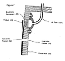
- Figure 7 provides a representative example of this workpiece former.
- the former includes wall 35 which may include a plurality of optional perforations or holes 33 and a breathable component 36 which is connected to an air tube 107.
- a dried product 28 including a hole or perforation 33 is attached to the wall 35.
- the workpiece former comprises: a wall enclosing an internal space, the wall having at least two portions, a first portion of the wall having a shape to which a workpiece would substantially conform; a plurality of perforations associated with the first portion of the wall; and at least one port for introducing vacuum, gas or liquid into the internal space, the port associated a second portion of the wall. If the perforations completely traverse the wall of the former, gas introduced into the internal space via the port would pass through a plurality of perforations and push away or eject any product material film blocking the perforation on the former to ensure the creation of a plurality of perforations in the workpiece.
- a plurality of optional breathable elements may be included in the first portion, preferably near an edge of the work product. These breathable elements further comprise tubes so as to allow the introduction of gas or liquid under sufficient pressure so as to push the dried workpiece away from the first portion of the wall, thus allowing for easy removal of the product from the former.
- the workpiece former may include a movable axis for rotating and/or moving the former to any suitable operating position.
- Figure 1 illustrates a representative workpiece former in the shape of underpants.
- the former has a plurality of embedded breathing components 105 positioned such that they are proximal to the edges of the leg and waist openings.
- the workpiece former includes a port 106.
- Figure 2 is a close-up view of an isolated breathing component in the shape of a hollow tube or finger.
- This method may be performed, for instance, as shown in Figures 3 and 4 .
- the workpiece former comprises a wall 100 surrounding or enclosing an interior space 108.
- a gas 100 e.g., air
- the gas passes through breathing component 105, pushing at least a portion of product 107 away from the mould so that an operator can readily grip and lift the product off the mould.
- the apparatus for producing a stretchable workpiece may comprise a wall, the wall may have single hole or a plurality of perforations to generate perforations in the workpiece; and a sprayer to generate a liquid product material spray onto the wall surface.
- the wall surface is a complex shape 3D workpiece former.
- the wall surface is a flat surface.
- the wall surface is a conveyer belt.
- the apparatus further comprises a positioning device associated with the sprayer or with the wall.
- the wall further comprises one or more breathable elements embedded in the wall, and a source of a gas or liquid for pushing the workpiece away from the wall.
- the apparatus for producing a stretchable workpiece optionally comprises a workpiece former and one or more sprayers, at least one sprayer directed to spraying liquid product material.
- An optional positioner for the sprayer may be further included in the apparatus.
- An optional controller maybe used as part of a positioner system.
- Representative apparati for preparing stretchable workpieces are shown in Figures 5 and 6 .
- Any suitable workpiece former may be used as part of the apparatus, including flat, two-dimensional or three-dimension workpieces having a complex shape to which the workpiece substantially conforms. In practicing this invention, the workpiece formers of the invention are preferred.
- suitable sprayer or spraying system may include, without limitation, air assisted based, airless based, electrostatic-based sprayers.
- these sprayers or sprayer systems may further include compressors, pressure tanks, pressure regulators, feeding pipes and other components known in the art for straying liquid polymers, elastomers such as latex, and other like materials.
- Representative dedicated airless guns for spraying liquid latex are commercially available for Graco N.V. of Belgium and by Spraying Systems Co. of IL, USA.
- the sprayer or sprayer system may consist of a single product material spray gun or may include additional spray guns for a variety of purposes such as creating different widths of spray bands, for spraying different compositions such as wetting agents or adhesives or for delivering different materials such as.coloured materials or agents or loose fibers.
- the spray guns preferably have a variable fan facility to enable the creation of thicker bands or layers of product material at desired areas.
- a separate flocking machine may be used independently of the sprayer system used for spraying materials.
- the flocking machine may be a pneumatic, electrostatic or combined flocking machine suitable for flocking natural or synthetic loose fibres over wet surfaces.
- the apparatus may further comprise a positioning device for precise controlled of the spray gun movements.
- the positioning device may be a robotic arm dedicated for spraying such as the robotic arm manufactured by Fanuc Robotics, ABB, Staubli for spraying paint or any other suitable mechanical device as known in the art, capable of moving the spray gun or the former or both in a precise controlled manner.
- Representative Figure 5 illustrates the preparation of a workpiece using a workpiece former 100, a sprayer for spraying product material 27 and a positioning device 26 for positioning the sprayer as shown in Figure 5 .
- liquid product material 29 is sprayed onto a former 100 as the former is being rotated along its movable axis 30.
- the movable axis 30 also allows for the adjustment of the former along any angle for provide for different operational positions. As product 28 is being formed, the position of either the former, the positioner or both are adjusted.
- the positioning device 26 is associated with a controller that adjusts the positional relationship between the spray gun 27 and the mould 100, adjust the fan pattern and control material atomisation and amount of liquid material per given unit of time. This will, in turn, allow for the precise control of the thickness of the sprayed layer. An increase in thickness will then be possible through repeat spraying of specific areas, slower movment over specific areas or heavier flow of the sprayed product material over specific areas. For example, to increase the thickness of the edge of a membrane for the purpose of reinforcing and strengthening the product.
- the positioning device may independently (or through the controller) control the timing and duration of spraying and will, in another aspect of this embodiment, enable the production of a multicoloured product and various thicknesses within it.
- Representative Figure 6 is identical to Figure 5 except that a separate controller is added to automatically adjust the position of either the former, the positioner, or both, based on data and instructions inputted into the controller.
- the controller may also adjust the rate of delivery of sprayed product and spray fan angle.
- the sprayer is a system that includes a plurality of spray guns for spraying product material, wetting agent, loose fibres, or other materials
- the controller may activate and control each individual spray gun and in a particular sequence.
- a plurality of dedicated positioners may be used, each positioner associated with a sprayer and all under the control of a single controller.
- a positioning sensor may be placed on the positioner, on the sprayer, or former so that distance and/or angle data between the sprayer and the former can be collected and processed by the controller.
- the apparatus may further comprise a vacuum system and a system for delivering loose fibres to the workpiece former.
- the vacuum allows the fibres to adhere to the former, with the use of a wetting agent as described above.
- the workpiece former may be perforated to allow for the production of products having perforations or holes as described above.
- the workpiece former may include one or more breathable elements embedded in the former.
- the apparatus may further include a source of a gas or liquid for pushing the workpiece away from the former.
- the source of the gas may be an air compressor.
- the source of the liquid may be a water reservoir attached to a pump.
- the apparatus and system may be provided for preparing a stretchable workpiece which employs a workpiece former, a sprayer, a positioner for the sprayer or former, and a controller whereby the controller adjusts the positional relationship between the former and the sprayer by moving the former, the sprayer, or both simultaneously.
- the sprayer may then properly spray the desired regions of the former.
- the system provides a fast and accurate way for spraying three-dimensional complex shaped formers to provide three-dimensional stretchable workpieces.
- a controller 31 controls the operation of the system. Examples of a controller include, but are not limited to, a computer, a terminal, a workstation, or some other electronic device capable of controlling the operation of the positioning device 26 and the former 100.
- the controller 31 includes a processor 12 and a memory 14.
- the processor 12 may comprise a microprocessor, a microcontroller, or any device which performs arithmetic, logic or control operations.
- the memory 14 may include any suitable memory device such as non-volatile memory devices such as a ROM, or magnetic or optical memory.
- the memory 14 may also include volatile memory devices such as a RAM device.
- Software may be included for the controller to control components within the system, such as the positioning device 26 and former 100.
- the controller 31 communicates with the positioning device 26, as described in more detail below.
- the positioning device 26 includes at least one motor 18 for moving a sprayer 27 (or alternatively moving the former 100).
- the positioning device 26 may further include at least one sensor 20 for sensing the position of the sprayer 27 (or alternatively sensing the position of the former 100).
- the sensors may be located within the controller 31.
- the positioning device 26 may be a robotic device as discussed above.
- sensing the relative position between the workpiece former and the spraying system may be provided by any other means, including, but not limited to, software, memory, mechanical routines.
- a method for preparing a workpiece may be performed as follows.
- the former 100 and sprayer 27 may be positioned relative to the former 100.
- the former 100 is positioned, by a positioning device 26 using motors 18, to a process starting point where the spray system and the workpiece former are in proper working position.
- the sprayer 27 is positioned by the positioning device 26 to a process starting point.
- both the former 100 and the sprayer 27 may be positioned by the positioning device 26.
- the sprayer 27 may include a variety of controllable parameters. Examples of the parameters include, but are not limited to, amount of liquid material delivered as a function of time, fan pattern, direction, controlled material atomization, and spray gun activation.
- the parameters for spray operation may be set automatically or manually. If set automatically, the parameters may be determined by accessing the memory 14 which stores the parameters for operation of the sprayer. Alternatively, the sprayer may scan the product using a sensor or sensors (such as a sensor or sensors included with the positioning device 16) on the former to determine aspects of the initial product such as material, thickness, color, etc. of the product. Based on this determination, the memory 14 may be accessed to set the parameters for the sprayer based on the aspects of the product so that further operation steps such as additional spraying of product material bands or layers at specific regions of the initial product for reinforcement may be performed.
- the positioning device 26 preferably repositions the former 100 or the sprayer 27, so that the new position on the former 100 is at the effective distance and angle of spray 29.
- the positioning device 26 moves or rotates the former 100 in front of the sprayer 27 according to data received from the distance determiner (not shown) and the sensing system 20.
- the positioning device 26 moves the sprayer 27.
- the positioning device 26 moves both the former 100 and the sprayer 27.
- the distance between the former 100 and the sprayer along the process can be pre-set for all the steps of the spraying process, for instance by mechanical routine, by software, or by any other suitable method known in the art so the positioning device 26 will correct the relative position between the workpiece former and the spraying system, during the movements along the production process.
- the determination and adjustment of relative position can be done in real-time by a measurement or sensing device, such as an optical device, ultrasonic device (for example, the one or more sensors 20 on the positioning device 26), any other proximity sensing device or other devices known in the art, and the data can be transferred to the controller 31 and to the positioning device 26 for appropriate adjustment of the location of the former 100.
- a measurement or sensing device such as an optical device, ultrasonic device (for example, the one or more sensors 20 on the positioning device 26), any other proximity sensing device or other devices known in the art, and the data can be transferred to the controller 31 and to the positioning device 26 for appropriate adjustment of the location of the former 100.
- FIG. 5 there is shown a perspective view of a workpiece being made on the former 100 with sprayer 27.
- the former 100 may be connected to a robotic device (which functions as the positioning device 26). The connection may be made by attaching pole 44 on the former 100 to the robotic device.
- the former 100 may then be moved.
- the robotic device may move the former 100 in any direction and to any position so that the spray 29 may contact any portion on the former 100.
- the sprayer 27 may remain stationary, focusing the spray 29 on a middle portion of the former 100 and the robot may move the former 100 in a circular direction so that the spraying occurs along the circumference of former 100.
- An industrial robot positions the former 100 using motors 18 of the positioning device 16 in front of sprayer 27 at such a distance that spray will contact at least a portion of the former 100.
- the parameters of spray 29 may also be adjusted to give optimal performance instead of, or in addition to changing the relative position between sprayer 27 and the former 100.
- the former 100 may then be rotated and repositioned by the robot, so that the next area to be sprayed is facing the sprayer 27, at substantially the same distance and substantially at the same angle to the spray 29.
- the robot may be required to make horizontal, vertical, and rotation movements, in order to bring the former 100 to the correct position in three-dimensional space relative to the sprayer. Accordingly, the robot may be required to work in any number of axes.
- the movement of the former 100 in front of the sprayer 27 can be done in a continuous and smooth manner, with all movements in all axes being done simultaneously so that with continuous spraying by sprayer 27, formation of the work piece can be achieved quickly.
- movement of the former 100 in front of sprayer 27 be performed step-by-step, in the case of where additional layers or bands of liquid product material or other materials may be sprayed on an existing product material layer to thicken and reinforce different areas of the product or to add other materials such as loose fibres. In this manner, there is no need to remove the product (such as a garment) from the former 100 in order to produce double-sided flocked garments or other products.
- an apparatus comprises: (a) a workpiece former having a shape to which the workpiece substantially conforms; (b) a sprayer to generate a liquid product material spray; and (c) a positioner that makes an adjustment to keep the spray substantially focused on the workpiece during the spraying process.
- the workpiece former may further comprise a movable axis to enable rotation and movement to a plurality of operating positions. Adjustments may be made by moving the workpiece former in a direction that changes the distance and angle between the former and the liquid product material sprayer. Alternatively, the adjustment may be made by moving the liquid product material sprayer in a direction that changes the distance between the former and the liquid product material sprayer. The adjust may be made by moving the sprayer or moving the former or both.
- the workpiece may be flat or two-dimensional. Alternatively, the workpiece may be three-dimensional and the workpiece former has a complex shape to which the workpiece substantially conforms.
- the apparatus further comprises: a processor; a memory; and a set of instructions stored in the memory and executable by the processor to move the sprayer and to cause the positioner to make the adjustment based on data stored in the memory that correlates the change in effective position to the sprayer to the workpiece, to adjust spray fan pattern, and to adjust amounts of liquid product material delivered per unit of time.
- the positioner may comprise a position sensing device (such as an optical sensor or ultrasonic sensor) and a motor. If desired, the positioner may operate in real-time to make the adjustment using input from the position sensing device.
- the sprayer comprises a plurality of different spray guns, at least one spray gun generates the liquid product material spray.
- the sprayer comprises a plurality of different spray guns, at least one spray gun generates the liquid product material spray, and another spray gun generates a loosc fibre spray.
- the sprayer comprises a plurality of different spray guns, at least one spray gun generates the liquid product material spray, a second spray gun generates a loose fibre spray and a third spray gun generates a water spray.
- the adjustment further comprises activating a spray gun.
- the workpiece former includes perforations, breathable elements embedded in the former, or both.
- the workpiece former may be any suitable former, preferably the formers of the present invention.
- an apparatus for preparing a workpiece using the method of the invention and having a sprayer comprises: a workpiece former, the workpiece former being movable to a plurality of operating positions and having a shape to which the workpiece substantially conforms; a positioner comprising a position sensing device; a processor; a memory; and a set of instructions stored in the memory and executable by the processor to move the sprayer to an operating position and to cause the positioner to make the adjustment to the sprayer to keep the liquid product material spray substantially focused on the workpiece during the spraying process.
- the adjustment being made using input from the position sensing device.
- the workpiece former may be flat or two-dimensional. Alternatively, the workpiece former may be three-dimensional and have a complex shape to which the workpiece substantially conforms.
- the apparatus comprises a spray gun for generating a liquid product material spray, a spray gun for generating a wetting agent spray, and a spray gun for generating a loose fibre spray.
- the apparatus comprises: a workpiece former, the workpiece former being movable to a plurality of operating positions and having a shape to which the workpiece substantially conforms; a positioner comprising a position sensing device; a processor; a memory; and a set of instructions stored in the memory and executable by the processor to move the sprayer to an operating position, to activate a spray gun, and to cause the positioner to make the adjustment to the sprayer to keep the spray substantially focused on the workpiece as the positioner moves the sprayer to an operating position that changes the distance and and relative angle between the workpiece and the spray due to the complex shape of the workpiece former, the adjustment being made using input from the position sensing device.
- the workpiece former may be flat or two-dimensional. Alternatively, the workpiece former may be three-dimensional and have a complex shape to which the workpiece substantially
- the method for preparing a three-dimensional workpiece that conforms to a workpiece former having a complex shape uses a liquid product material spray, a loose fibre spray, and an optional wetting agent spray, each spray produced by individual spray guns of a sprayer.
- the method may comprise: changing the positional relationship between the sprayer and the workpiece former to establish a first operating position where the surface of the workpiece is substantially at the effective distance where the spray meets the workpiece; changing the positional relationship between the sprayer and the workpiece former to establish a second operating position that changes the distance between the workpiece and the sprayer due to the complex shape of the workpiece former; and making an adjustment to keep the spray substantially focused on the workpiece at the second operating position.
- the adjustment comprises moving the workpiece former in a direction substantially parallel to an axis about which the spray is symmetric.
- the adjustment comprises moving the sprayer in a direction substantially parallel to an axis about which the spray is symmetric.
- the method further comprises: sensing the change in distance and/or the angle between the workpiece and the sprayer caused by changing the positional relationship between the sprayer and the workpiece former from the first operating position to the second operating position, wherein the adjustment is made in response to the sensed change.
- the method further comprising: referring to data stored in a memory that correlates the change in distance and/or angle between the workpiece and the sprayer to motion from the first operating position to the second operating position, wherein the adjustment is made in response to the data stored in the memory.
- the method comprises: establishing a first operating position where the surface of the workpiece former is at an effective distance where the liquid product material spray meets the workpiece former; activating the sprayer to generate a liquid product material spray onto the workpiece former; changing the positional relationship between the sprayer and the workpiece former to establish a second operating position where the surface of the workpiece is at an effective distance where the liquid product material spray meets the workpiece former; activating the sprayer; changing the positional relationship between the sprayer and the workpiece former to establish a second operating position that changes the distance and/or angle between the workpiece and the sprayer due to the complex shape of the workpiece former; and making an adjustment to keep the liquid product material spray substantially focused on the workpiece at the second operating position.
- the method further comprises: deactivating the sprayer before establishing the second operating position; and activating the sprayer after the second operating position is established.
- the sprayer remains activated as the positional relationship between the sprayer and the workpiece former is changed.
- a method for preparing a workpiece that conforms to a shape of a workpiece former, the method using a liquid product material spray produced by a sprayer.
- the method comprises: changing the positional relationship between the sprayer and the workpiece former to establish a first operating position where the surface of the workpiece is substantially at the effective position where the spray meets the workpiece; changing the positional relationship between the sprayer and the workpiece former to establish a second operating position that changes the relative position between the workpiece and the sprayer due to the shape of the workpiece former; and making an adjustment to keep the liquid product material spray substantially focused on the workpiece at the second operating position.
- the former may be flat or two-dimensional. Alternatively, the former may be three-dimensional and the workpiece substantially conforms to the complex shape of a workpiece former.
- the adjustment comprises moving the workpiece former in a direction substantially parallel to an axis about which the liquid product material spray is symmetric.
- the adjustment comprises moving the sprayer in a direction substantially parallel to an axis about which the liquid product material spray is symmetric.
- the method further comprises: sensing the change in distance and/or angle between the workpiece and the sprayer caused by changing the positional relationship between the sprayer and the workpiece former from the first operating position to the second operating position, wherein the adjustment is made in response to the sensed change.
- the method further comprises: referring to data stored in a memory that correlates the change in relative position between the workpiece and the sprayer to motion from the first operating position to the second operating position, wherein the adjustment is made in response to the data stored in the memory.
- a method for producing a workpiece that conforms to a shape of a workpiece former.
- the method using an liquid product material spray, a loose fibre spray, and a wetting agent spray produced by individual guns of a sprayer, the method comprising the following steps in order: establishing a first operating position where the surface of the workpiece former is at an effective position where the liquid product material spray meets the workpiece former; activating a spray gun of a sprayer to generate a spray onto the workpiece former; changing the positional relationship between the sprayer and the workpiece former to establish a second operating position where the surface of the workpiece is at an effective position where the liquid product material spray meets the workpiece former; activating a spray gun of a sprayer to generate a spray; changing the positional relationship between the sprayer and the workpiece former to establish a second operating position that changes the distance and/or angle between the workpiece and the sprayer due to the complex shape of the workpiece former; and making an adjustment to keep the spray substantially focused on the workpiece at the second
- the former may be flat or two-dimensional. Alternatively, the former may be three-dimensional and the workpiece substantially conforms to the complex shape of a workpiece former.
- the method further comprises: deactivating the sprayer before establishing the second operating position; and activating the sprayer after the second operating position is established.
- sprayer remains activated as the positional relationship between the sprayer and the workpiece former is changed.
Landscapes
- Engineering & Computer Science (AREA)
- Mechanical Engineering (AREA)
- Textile Engineering (AREA)
- Physics & Mathematics (AREA)
- Fluid Mechanics (AREA)
- Application Of Or Painting With Fluid Materials (AREA)
- Moulding By Coating Moulds (AREA)
- Reinforced Plastic Materials (AREA)
- Extrusion Moulding Of Plastics Or The Like (AREA)
Applications Claiming Priority (2)
| Application Number | Priority Date | Filing Date | Title |
|---|---|---|---|
| US62548004P | 2004-11-05 | 2004-11-05 | |
| PCT/IB2005/004148 WO2006092666A2 (en) | 2004-11-05 | 2005-11-07 | Method and apparatus to produce stretchable products |
Publications (2)
| Publication Number | Publication Date |
|---|---|
| EP1807253A2 EP1807253A2 (en) | 2007-07-18 |
| EP1807253B1 true EP1807253B1 (en) | 2013-04-10 |
Family
ID=36763138
Family Applications (1)
| Application Number | Title | Priority Date | Filing Date |
|---|---|---|---|
| EP05857369.2A Expired - Lifetime EP1807253B1 (en) | 2004-11-05 | 2005-11-07 | Method to produce stretchable products |
Country Status (9)
| Country | Link |
|---|---|
| US (2) | US7767133B2 (pt) |
| EP (1) | EP1807253B1 (pt) |
| JP (1) | JP5132315B2 (pt) |
| CN (1) | CN101155677B (pt) |
| BR (1) | BRPI0520656B1 (pt) |
| CA (1) | CA2586571C (pt) |
| ES (1) | ES2419161T3 (pt) |
| WO (1) | WO2006092666A2 (pt) |
| ZA (1) | ZA200704148B (pt) |
Families Citing this family (35)
| Publication number | Priority date | Publication date | Assignee | Title |
|---|---|---|---|---|
| US9731319B2 (en) * | 2004-11-05 | 2017-08-15 | Tamicare Ltd. | Stretchable sheets comprising a variety of layers and zones and methods to produce such products |
| US7901740B2 (en) * | 2004-11-05 | 2011-03-08 | Tamicare Ltd. | Methods to produce stretchable products |
| EP1807253B1 (en) * | 2004-11-05 | 2013-04-10 | Tamicare Ltd. | Method to produce stretchable products |
| MX2009005373A (es) * | 2006-11-20 | 2009-10-05 | Tamicare Ltd | Metodo y aparato para producir un producto usando un armazon de molde flexible. |
| US8916073B2 (en) * | 2007-02-23 | 2014-12-23 | Richard W. Rydin | Method of making a natural rubber vacuum bag by spray processes, natural rubber vacuum bag made using spray process, and method for using natural rubber bag made using spray process |
| WO2008144035A1 (en) | 2007-05-18 | 2008-11-27 | Rydin Richard W | Vacuum bag with integral fluid transfer conduits and seals for resin transfer and other processes |
| BRPI0820056A2 (pt) * | 2007-11-09 | 2015-05-12 | Tamicare Ltd | Roupa íntima descartável melhorada com um painel de abertura frontal |
| NO20092970A (no) | 2009-09-08 | 2010-11-22 | Hoegskolen I Soeroest Norge | Storskala skallkonstruksjoner |
| JP2014501857A (ja) | 2010-12-17 | 2014-01-23 | タミケア リミテッド | 形状保持不織布製品素材および製造方法 |
| US10343310B2 (en) * | 2011-02-10 | 2019-07-09 | Eps Offshore Oil Trading Plc | Consumable bitumen bag for packaging bitumen and method of forming the bitumen bag |
| JP6022761B2 (ja) * | 2011-12-02 | 2016-11-09 | スリーエム イノベイティブ プロパティズ カンパニー | 両面接着材の製造方法 |
| US20130330467A1 (en) | 2012-06-12 | 2013-12-12 | Abb Inc. | Method of applying a thin spray-on liner and robotic applicator therefor |
| US9480829B2 (en) | 2013-01-17 | 2016-11-01 | Tamicare Ltd. | All direction stretchable dressing article associated with curable materials |
| WO2014152938A1 (en) | 2013-03-14 | 2014-09-25 | Altria Client Services Inc. | Product portion enrobing machines and methods |
| CA2905169C (en) * | 2013-03-15 | 2021-03-23 | Tamicare Ltd. | An apparatus for producing a nonwoven product in a non-industrial environment |
| EP2967122B1 (en) | 2013-03-15 | 2025-05-07 | Altria Client Services LLC | Pouch material for smokeless tobacco and tobacco substitute products |
| US9078947B2 (en) | 2013-03-15 | 2015-07-14 | Kimberly-Clark Worldwide, Inc. | Composition for forming a porous absorbent structure |
| WO2015022582A1 (en) | 2013-08-15 | 2015-02-19 | Tamicare Ltd. | Method for colouring products on a mould surface |
| KR102350783B1 (ko) | 2013-12-31 | 2022-01-14 | 킴벌리-클라크 월드와이드, 인크. | 경질 표면 세정 방법 |
| JP6568218B2 (ja) | 2014-12-23 | 2019-08-28 | ブリヂストン アメリカズ タイヤ オペレーションズ、 エルエルシー | 化学線硬化型高分子混合物、硬化高分子混合物、及び関連するプロセス |
| GB2544481B (en) * | 2015-11-16 | 2019-12-11 | Century International Enterprises Ltd | A wearable article and a method for producing a wearable article |
| US11097531B2 (en) | 2015-12-17 | 2021-08-24 | Bridgestone Americas Tire Operations, Llc | Additive manufacturing cartridges and processes for producing cured polymeric products by additive manufacturing |
| CN109069160B (zh) | 2016-03-17 | 2022-05-17 | S·珍耶那曼 | 封堵解剖结构 |
| US12232737B2 (en) | 2016-03-17 | 2025-02-25 | Eclipse Medical Limited | Occluding anatomical structures |
| WO2017212337A1 (en) | 2016-06-08 | 2017-12-14 | Tamicare Ltd. | Liquid polymer sprayed sheet with fused layers and variable ratio of polymers droplets and entrapped bubbles |
| US11453161B2 (en) | 2016-10-27 | 2022-09-27 | Bridgestone Americas Tire Operations, Llc | Processes for producing cured polymeric products by additive manufacturing |
| US10907256B2 (en) | 2016-12-22 | 2021-02-02 | Raytheon Technologies Corporation | Reinforcement of a deposited structure forming a metal matrix composite |
| US10648084B2 (en) * | 2016-12-22 | 2020-05-12 | United Technologies Corporation | Material deposition to form a sheet structure |
| CN108636726A (zh) * | 2018-07-16 | 2018-10-12 | 宁波尚美隆汽车饰件有限公司 | 机器人植绒设备植绒方法及采用该方法的机器人植绒设备 |
| GB2593871A (en) * | 2020-03-30 | 2021-10-13 | Best Perwira Gloves Sdn Bhd | Method of manufacturing latex rubber articles |
| DE102020129628A1 (de) * | 2020-11-10 | 2022-05-12 | Norafin Industries (Germany) Gmbh | Vorrichtung zum Verfestigen eines Fasergebildes |
| JP7123356B2 (ja) * | 2021-01-07 | 2022-08-23 | 株式会社 ミタテ工房 | 立体物造形装置および立体物造形方法 |
| WO2022248615A2 (en) * | 2021-05-26 | 2022-12-01 | INSERM (Institut National de la Santé et de la Recherche Médicale) | Hexokinase-derived peptides and therapeutical uses thereof |
| FR3145310A1 (fr) | 2023-01-26 | 2024-08-02 | Decathlon | Pneu dont la bande de roulement est formée entièrement ou en partie d’un matériau composite de construction moulée unitaire |
| US20240389687A1 (en) | 2023-05-26 | 2024-11-28 | Nike, Inc. | Three dimensional molds for liquid spray deposition, and methods and systems for creating articles of apparel using same |
Citations (1)
| Publication number | Priority date | Publication date | Assignee | Title |
|---|---|---|---|---|
| US2527501A (en) * | 1949-03-28 | 1950-10-24 | Walter R Saks | Process of producing flocked articles |
Family Cites Families (49)
| Publication number | Priority date | Publication date | Assignee | Title |
|---|---|---|---|---|
| GB509196A (en) | 1937-08-11 | 1939-07-12 | Fernand Frederic Schwartz | Improvements in the manufacture of rubber articles by the spraying of latex |
| GB550391A (en) | 1941-04-01 | 1943-01-06 | Charles Fletcher Lumb | Spraying rubber latex |
| US2691611A (en) | 1952-04-10 | 1954-10-12 | Walter R Saks | Process of producing flocked articls |
| US3032774A (en) * | 1955-11-30 | 1962-05-08 | American Viscose Corp | Seamless garment |
| US3027273A (en) | 1957-12-16 | 1962-03-27 | Hauserman Co E F | Spray control system |
| GB965901A (en) * | 1959-04-29 | 1964-08-06 | Robert Edward Chapman | Improvements in or relating to the manufacture of protective clothing |
| CH453280A (de) * | 1967-09-20 | 1968-06-14 | Carl Dr Werner | Verfahren zur Herstellung eines Kleidungsstückes und nach dem Verfahren hergestelltes Kleidungsstück |
| CH492410A (de) * | 1969-08-25 | 1970-06-30 | Triumph Universa Gmbh | Damenlangbeinhose |
| GB1356465A (en) | 1971-05-25 | 1974-06-12 | Jowitt J A | Disposable sanitary knickers |
| US3791783A (en) * | 1971-06-28 | 1974-02-12 | Structural Fibers | Apparatus for forming fiber preforms |
| US4102964A (en) | 1974-12-23 | 1978-07-25 | Facetglas, Inc. | Method for manufacturing rigid articles having a cushioned surface |
| US4095638A (en) * | 1975-03-25 | 1978-06-20 | The Goodyear Tire & Rubber Company | Manufacturing of inner tubes for tires |
| US4223101A (en) * | 1978-07-17 | 1980-09-16 | Inmont Corporation | Method of producing fibrous structure |
| GB2074085A (en) * | 1980-03-19 | 1981-10-28 | Telford Safety Glove Co Ltd | Moulding fibrous gloves |
| JPS5887102A (ja) | 1981-11-19 | 1983-05-24 | Kanegafuchi Chem Ind Co Ltd | 凝固ラテツクスの製造方法および装置 |
| US4519098A (en) | 1983-06-08 | 1985-05-28 | Becton, Dickinson And Company | Wearing apparel and methods for manufacturing of wearing apparel |
| DE3330493C1 (de) | 1983-08-24 | 1984-11-22 | Flachglas AG, 8510 Fürth | Verfahren und Vorrichtung zum Herstellen von strukturierten, beflockten Oberflächen |
| JPS6063163A (ja) * | 1983-09-18 | 1985-04-11 | 住友電気工業株式会社 | 可撓性膜材製品の製造方法 |
| US5338565A (en) | 1987-07-17 | 1994-08-16 | Robin R. T. Shlenker | Method of forming a membrane, especially a latex membrane, having a biocide barrier |
| US4808458A (en) | 1988-02-08 | 1989-02-28 | Gencorp Inc. | Textured suede |
| US5138719A (en) | 1988-12-01 | 1992-08-18 | Hutchinson, S.A. | Gloves, finger stalls and similar protective and operational articles, and processes for their manufacture |
| WO1992010119A1 (en) | 1990-12-07 | 1992-06-25 | Creme Art Corporation | Foam coated cloth, method for coating and foam article covered by cloth |
| US5196240A (en) * | 1991-03-18 | 1993-03-23 | Stockwell Gregg M | Seamless bodysuit and a method for fabricating same |
| JPH04294131A (ja) * | 1991-03-25 | 1992-10-19 | Sekisui Chem Co Ltd | Frp成形方法及びfrp成形装置 |
| CH682288A5 (en) | 1991-10-02 | 1993-08-31 | Ursula Horisberger | Water-tight slip for protecting women against infection during swimming - is worn under normal swim wear, and is made of rubber with gauze pad in crotch area |
| CA2058210C (en) | 1991-12-20 | 1995-02-14 | Clive C. Solomons | Method of forming a membrane, especially a latex membrane, having a biocide barrier |
| GB9206434D0 (en) * | 1992-03-21 | 1992-05-06 | Johnson Keith D B | Rapid clothing manufacture |
| JP3197943B2 (ja) | 1992-04-30 | 2001-08-13 | エステー化学株式会社 | 天然ゴム製起毛製品およびその製造法 |
| US5429682A (en) * | 1993-08-19 | 1995-07-04 | Advanced Robotics Technologies | Automated three-dimensional precision coatings application apparatus |
| GB9625765D0 (en) * | 1996-12-11 | 1997-01-29 | Lrc Products | Process and apparatus for forming a thin-walled article |
| FI103770B (fi) * | 1998-05-15 | 1999-09-30 | Oms Optomedical Systems Ltd Oy | Menetelmä ja laitteisto ohutseinämäisen kappaleen valmistamiseen |
| JP3625671B2 (ja) * | 1998-07-29 | 2005-03-02 | 博明 立石 | ストリング体の吹き付け装置、ストリング体の吹き付け方法、ストリング体の吹き付け物の生産装置及びストリング体の吹き付け物の生産方法 |
| IL125695A0 (en) | 1998-08-07 | 1999-04-11 | Giloh Tamar | A protective undergarment |
| US7354424B2 (en) | 1998-08-07 | 2008-04-08 | Tamicare Ltd. | Protective garment |
| CN1335870A (zh) | 1998-12-29 | 2002-02-13 | 韦尔蒂股份有限公司 | 用天然聚合物生产产品的方法及由此制得的产品 |
| US6645884B1 (en) | 1999-07-09 | 2003-11-11 | Applied Materials, Inc. | Method of forming a silicon nitride layer on a substrate |
| MY133355A (en) | 2000-02-08 | 2007-11-30 | Ansell Healthcare Prod Inc | Production of gloves and other articles of flexible polymer material |
| JP2001271273A (ja) | 2000-03-21 | 2001-10-02 | Fujikura Rubber Ltd | ラテックス層の形成方法 |
| US6699419B1 (en) | 2000-06-05 | 2004-03-02 | General Motors Corporation | Method of forming a composite article with a textured surface and mold therefor |
| JP4016191B2 (ja) * | 2002-06-28 | 2007-12-05 | 株式会社イノアックコーポレーション | ウレタン表皮成形装置の成形型位置決め構造体 |
| US7585526B2 (en) | 2002-11-07 | 2009-09-08 | Smarthealth, Inc. | Flexible elastomer articles and methods of manufacturing |
| ATE355950T1 (de) | 2002-12-17 | 2007-03-15 | Integrated Biomaterial & Cell | Vorrichtung und ihre verwendung zur herstellung von porösen membranen für die medizinische verwendung |
| EP1459862A1 (en) * | 2003-03-18 | 2004-09-22 | Askle | Process for manufacturing moulded articles and articles having integral skin thus obtained |
| US20050194713A1 (en) | 2003-12-29 | 2005-09-08 | John Erickson | Method of making a molded article |
| GB2400051B (en) | 2004-03-31 | 2005-03-09 | John Ward Ceylon | Polymeric garment material |
| US20050222543A1 (en) | 2004-04-01 | 2005-10-06 | Zechuan Shao | Skin-care protective gloves and manufacturing method |
| EP1807253B1 (en) * | 2004-11-05 | 2013-04-10 | Tamicare Ltd. | Method to produce stretchable products |
| US7901740B2 (en) * | 2004-11-05 | 2011-03-08 | Tamicare Ltd. | Methods to produce stretchable products |
| ITFI20050172A1 (it) | 2005-08-03 | 2007-02-04 | Fintex & Partners Italia S P A | Metodo per la produzione di un manufatto nastriforme per la produzione di articoli assorbenti e simili, manufatto cosi' ottenuto ed articolo assorbente comprendente detto manufatto |
-
2005
- 2005-11-07 EP EP05857369.2A patent/EP1807253B1/en not_active Expired - Lifetime
- 2005-11-07 ES ES05857369T patent/ES2419161T3/es not_active Expired - Lifetime
- 2005-11-07 CA CA2586571A patent/CA2586571C/en not_active Expired - Fee Related
- 2005-11-07 JP JP2007539658A patent/JP5132315B2/ja not_active Expired - Lifetime
- 2005-11-07 US US11/268,684 patent/US7767133B2/en active Active
- 2005-11-07 WO PCT/IB2005/004148 patent/WO2006092666A2/en not_active Ceased
- 2005-11-07 CN CN200580045883.7A patent/CN101155677B/zh not_active Expired - Lifetime
- 2005-11-07 BR BRPI0520656A patent/BRPI0520656B1/pt not_active IP Right Cessation
-
2007
- 2007-05-22 ZA ZA200704148A patent/ZA200704148B/xx unknown
-
2010
- 2010-07-09 US US12/833,192 patent/US20110008478A1/en not_active Abandoned
Patent Citations (1)
| Publication number | Priority date | Publication date | Assignee | Title |
|---|---|---|---|---|
| US2527501A (en) * | 1949-03-28 | 1950-10-24 | Walter R Saks | Process of producing flocked articles |
Also Published As
| Publication number | Publication date |
|---|---|
| BRPI0520656A2 (pt) | 2009-07-21 |
| WO2006092666A3 (en) | 2007-03-08 |
| EP1807253A2 (en) | 2007-07-18 |
| CN101155677B (zh) | 2011-05-11 |
| US20110008478A1 (en) | 2011-01-13 |
| ES2419161T3 (es) | 2013-08-19 |
| JP2008518814A (ja) | 2008-06-05 |
| JP5132315B2 (ja) | 2013-01-30 |
| BRPI0520656B1 (pt) | 2016-11-29 |
| US7767133B2 (en) | 2010-08-03 |
| CA2586571C (en) | 2013-01-29 |
| CA2586571A1 (en) | 2006-09-08 |
| CN101155677A (zh) | 2008-04-02 |
| WO2006092666A2 (en) | 2006-09-08 |
| ZA200704148B (en) | 2010-08-25 |
| US20060113714A1 (en) | 2006-06-01 |
Similar Documents
| Publication | Publication Date | Title |
|---|---|---|
| EP1807253B1 (en) | Method to produce stretchable products | |
| AU2009229279B2 (en) | Methods to produce stretchable products | |
| US20220258385A1 (en) | Method for producing a biocompatible three-dimensional object | |
| TWI580839B (zh) | 不織布織品、不織布鞋幫、不織布物品的製造方法及含有不織布織品的物品 | |
| JP2021177023A (ja) | 統合されたエラストマー製品製造システム及びプロセス | |
| CN105102704B (zh) | 用于在非工业环境中生产无纺产品的设备 | |
| KR20100098791A (ko) | 코팅장갑의 잔액처리 방법 및 장치 | |
| AU2021247046A1 (en) | Method of manufacturing latex rubber articles | |
| CN220592807U (zh) | 一种义齿生产喷砂机 | |
| GB2481830A (en) | Applying adhesive to a fabric |
Legal Events
| Date | Code | Title | Description |
|---|---|---|---|
| PUAI | Public reference made under article 153(3) epc to a published international application that has entered the european phase |
Free format text: ORIGINAL CODE: 0009012 |
|
| 17P | Request for examination filed |
Effective date: 20070510 |
|
| AK | Designated contracting states |
Kind code of ref document: A2 Designated state(s): AT BE BG CH CY CZ DE DK EE ES FI FR GB GR HU IE IS IT LI LT LU LV MC NL PL PT RO SE SI SK TR |
|
| AX | Request for extension of the european patent |
Extension state: AL BA HR MK YU |
|
| DAX | Request for extension of the european patent (deleted) | ||
| 17Q | First examination report despatched |
Effective date: 20090415 |
|
| GRAP | Despatch of communication of intention to grant a patent |
Free format text: ORIGINAL CODE: EPIDOSNIGR1 |
|
| GRAS | Grant fee paid |
Free format text: ORIGINAL CODE: EPIDOSNIGR3 |
|
| GRAP | Despatch of communication of intention to grant a patent |
Free format text: ORIGINAL CODE: EPIDOSNIGR1 |
|
| GRAA | (expected) grant |
Free format text: ORIGINAL CODE: 0009210 |
|
| AK | Designated contracting states |
Kind code of ref document: B1 Designated state(s): AT BE BG CH CY CZ DE DK EE ES FI FR GB GR HU IE IS IT LI LT LU LV MC NL PL PT RO SE SI SK TR |
|
| REG | Reference to a national code |
Ref country code: GB Ref legal event code: FG4D |
|
| REG | Reference to a national code |
Ref country code: CH Ref legal event code: EP Ref country code: AT Ref legal event code: REF Ref document number: 605726 Country of ref document: AT Kind code of ref document: T Effective date: 20130415 |
|
| REG | Reference to a national code |
Ref country code: IE Ref legal event code: FG4D |
|
| REG | Reference to a national code |
Ref country code: DE Ref legal event code: R096 Ref document number: 602005039080 Country of ref document: DE Effective date: 20130606 |
|
| REG | Reference to a national code |
Ref country code: ES Ref legal event code: FG2A Ref document number: 2419161 Country of ref document: ES Kind code of ref document: T3 Effective date: 20130819 |
|
| PG25 | Lapsed in a contracting state [announced via postgrant information from national office to epo] |
Ref country code: SI Free format text: LAPSE BECAUSE OF FAILURE TO SUBMIT A TRANSLATION OF THE DESCRIPTION OR TO PAY THE FEE WITHIN THE PRESCRIBED TIME-LIMIT Effective date: 20130410 |
|
| REG | Reference to a national code |
Ref country code: AT Ref legal event code: MK05 Ref document number: 605726 Country of ref document: AT Kind code of ref document: T Effective date: 20130410 |
|
| REG | Reference to a national code |
Ref country code: NL Ref legal event code: VDEP Effective date: 20130410 Ref country code: LT Ref legal event code: MG4D |
|
| PG25 | Lapsed in a contracting state [announced via postgrant information from national office to epo] |
Ref country code: LT Free format text: LAPSE BECAUSE OF FAILURE TO SUBMIT A TRANSLATION OF THE DESCRIPTION OR TO PAY THE FEE WITHIN THE PRESCRIBED TIME-LIMIT Effective date: 20130410 Ref country code: AT Free format text: LAPSE BECAUSE OF FAILURE TO SUBMIT A TRANSLATION OF THE DESCRIPTION OR TO PAY THE FEE WITHIN THE PRESCRIBED TIME-LIMIT Effective date: 20130410 Ref country code: PT Free format text: LAPSE BECAUSE OF FAILURE TO SUBMIT A TRANSLATION OF THE DESCRIPTION OR TO PAY THE FEE WITHIN THE PRESCRIBED TIME-LIMIT Effective date: 20130812 Ref country code: GR Free format text: LAPSE BECAUSE OF FAILURE TO SUBMIT A TRANSLATION OF THE DESCRIPTION OR TO PAY THE FEE WITHIN THE PRESCRIBED TIME-LIMIT Effective date: 20130711 Ref country code: FI Free format text: LAPSE BECAUSE OF FAILURE TO SUBMIT A TRANSLATION OF THE DESCRIPTION OR TO PAY THE FEE WITHIN THE PRESCRIBED TIME-LIMIT Effective date: 20130410 Ref country code: IS Free format text: LAPSE BECAUSE OF FAILURE TO SUBMIT A TRANSLATION OF THE DESCRIPTION OR TO PAY THE FEE WITHIN THE PRESCRIBED TIME-LIMIT Effective date: 20130810 Ref country code: NL Free format text: LAPSE BECAUSE OF FAILURE TO SUBMIT A TRANSLATION OF THE DESCRIPTION OR TO PAY THE FEE WITHIN THE PRESCRIBED TIME-LIMIT Effective date: 20130410 Ref country code: SE Free format text: LAPSE BECAUSE OF FAILURE TO SUBMIT A TRANSLATION OF THE DESCRIPTION OR TO PAY THE FEE WITHIN THE PRESCRIBED TIME-LIMIT Effective date: 20130410 |
|
| PG25 | Lapsed in a contracting state [announced via postgrant information from national office to epo] |
Ref country code: BG Free format text: LAPSE BECAUSE OF FAILURE TO SUBMIT A TRANSLATION OF THE DESCRIPTION OR TO PAY THE FEE WITHIN THE PRESCRIBED TIME-LIMIT Effective date: 20130710 Ref country code: CY Free format text: LAPSE BECAUSE OF FAILURE TO SUBMIT A TRANSLATION OF THE DESCRIPTION OR TO PAY THE FEE WITHIN THE PRESCRIBED TIME-LIMIT Effective date: 20130410 Ref country code: PL Free format text: LAPSE BECAUSE OF FAILURE TO SUBMIT A TRANSLATION OF THE DESCRIPTION OR TO PAY THE FEE WITHIN THE PRESCRIBED TIME-LIMIT Effective date: 20130410 Ref country code: LV Free format text: LAPSE BECAUSE OF FAILURE TO SUBMIT A TRANSLATION OF THE DESCRIPTION OR TO PAY THE FEE WITHIN THE PRESCRIBED TIME-LIMIT Effective date: 20130410 |
|
| PG25 | Lapsed in a contracting state [announced via postgrant information from national office to epo] |
Ref country code: DK Free format text: LAPSE BECAUSE OF FAILURE TO SUBMIT A TRANSLATION OF THE DESCRIPTION OR TO PAY THE FEE WITHIN THE PRESCRIBED TIME-LIMIT Effective date: 20130410 Ref country code: CZ Free format text: LAPSE BECAUSE OF FAILURE TO SUBMIT A TRANSLATION OF THE DESCRIPTION OR TO PAY THE FEE WITHIN THE PRESCRIBED TIME-LIMIT Effective date: 20130410 Ref country code: EE Free format text: LAPSE BECAUSE OF FAILURE TO SUBMIT A TRANSLATION OF THE DESCRIPTION OR TO PAY THE FEE WITHIN THE PRESCRIBED TIME-LIMIT Effective date: 20130410 Ref country code: SK Free format text: LAPSE BECAUSE OF FAILURE TO SUBMIT A TRANSLATION OF THE DESCRIPTION OR TO PAY THE FEE WITHIN THE PRESCRIBED TIME-LIMIT Effective date: 20130410 |
|
| PLBE | No opposition filed within time limit |
Free format text: ORIGINAL CODE: 0009261 |
|
| STAA | Information on the status of an ep patent application or granted ep patent |
Free format text: STATUS: NO OPPOSITION FILED WITHIN TIME LIMIT |
|
| PG25 | Lapsed in a contracting state [announced via postgrant information from national office to epo] |
Ref country code: RO Free format text: LAPSE BECAUSE OF FAILURE TO SUBMIT A TRANSLATION OF THE DESCRIPTION OR TO PAY THE FEE WITHIN THE PRESCRIBED TIME-LIMIT Effective date: 20130410 |
|
| 26N | No opposition filed |
Effective date: 20140113 |
|
| REG | Reference to a national code |
Ref country code: DE Ref legal event code: R097 Ref document number: 602005039080 Country of ref document: DE Effective date: 20140113 |
|
| REG | Reference to a national code |
Ref country code: CH Ref legal event code: PL |
|
| PG25 | Lapsed in a contracting state [announced via postgrant information from national office to epo] |
Ref country code: MC Free format text: LAPSE BECAUSE OF FAILURE TO SUBMIT A TRANSLATION OF THE DESCRIPTION OR TO PAY THE FEE WITHIN THE PRESCRIBED TIME-LIMIT Effective date: 20130410 Ref country code: LI Free format text: LAPSE BECAUSE OF NON-PAYMENT OF DUE FEES Effective date: 20131130 Ref country code: CH Free format text: LAPSE BECAUSE OF NON-PAYMENT OF DUE FEES Effective date: 20131130 |
|
| REG | Reference to a national code |
Ref country code: FR Ref legal event code: ST Effective date: 20140731 |
|
| PG25 | Lapsed in a contracting state [announced via postgrant information from national office to epo] |
Ref country code: FR Free format text: LAPSE BECAUSE OF NON-PAYMENT OF DUE FEES Effective date: 20131202 |
|
| PG25 | Lapsed in a contracting state [announced via postgrant information from national office to epo] |
Ref country code: LU Free format text: LAPSE BECAUSE OF NON-PAYMENT OF DUE FEES Effective date: 20131107 Ref country code: HU Free format text: LAPSE BECAUSE OF FAILURE TO SUBMIT A TRANSLATION OF THE DESCRIPTION OR TO PAY THE FEE WITHIN THE PRESCRIBED TIME-LIMIT; INVALID AB INITIO Effective date: 20051107 |
|
| PGFP | Annual fee paid to national office [announced via postgrant information from national office to epo] |
Ref country code: BE Payment date: 20191127 Year of fee payment: 15 |
|
| REG | Reference to a national code |
Ref country code: BE Ref legal event code: MM Effective date: 20201130 |
|
| PG25 | Lapsed in a contracting state [announced via postgrant information from national office to epo] |
Ref country code: BE Free format text: LAPSE BECAUSE OF NON-PAYMENT OF DUE FEES Effective date: 20201130 |
|
| PGFP | Annual fee paid to national office [announced via postgrant information from national office to epo] |
Ref country code: GB Payment date: 20241230 Year of fee payment: 20 |
|
| PGFP | Annual fee paid to national office [announced via postgrant information from national office to epo] |
Ref country code: IE Payment date: 20241202 Year of fee payment: 20 |
|
| PGFP | Annual fee paid to national office [announced via postgrant information from national office to epo] |
Ref country code: IT Payment date: 20241128 Year of fee payment: 20 |
|
| PGFP | Annual fee paid to national office [announced via postgrant information from national office to epo] |
Ref country code: TR Payment date: 20241107 Year of fee payment: 20 |
|
| PGFP | Annual fee paid to national office [announced via postgrant information from national office to epo] |
Ref country code: DE Payment date: 20250129 Year of fee payment: 20 |
|
| PGFP | Annual fee paid to national office [announced via postgrant information from national office to epo] |
Ref country code: ES Payment date: 20250220 Year of fee payment: 20 |
|
| REG | Reference to a national code |
Ref country code: DE Ref legal event code: R071 Ref document number: 602005039080 Country of ref document: DE |
|
| REG | Reference to a national code |
Ref country code: GB Ref legal event code: PE20 Expiry date: 20251106 |
|
| REG | Reference to a national code |
Ref country code: ES Ref legal event code: FD2A Effective date: 20251204 |
|
| REG | Reference to a national code |
Ref country code: IE Ref legal event code: MK9A |
|
| PG25 | Lapsed in a contracting state [announced via postgrant information from national office to epo] |
Ref country code: IE Free format text: LAPSE BECAUSE OF EXPIRATION OF PROTECTION Effective date: 20251107 |
|
| PG25 | Lapsed in a contracting state [announced via postgrant information from national office to epo] |
Ref country code: ES Free format text: LAPSE BECAUSE OF EXPIRATION OF PROTECTION Effective date: 20251108 |