EP1807616B1 - Akustischer absorber für flugtriebwerke - Google Patents
Akustischer absorber für flugtriebwerke Download PDFInfo
- Publication number
- EP1807616B1 EP1807616B1 EP05806861.0A EP05806861A EP1807616B1 EP 1807616 B1 EP1807616 B1 EP 1807616B1 EP 05806861 A EP05806861 A EP 05806861A EP 1807616 B1 EP1807616 B1 EP 1807616B1
- Authority
- EP
- European Patent Office
- Prior art keywords
- honeycomb
- folding
- acoustic absorber
- absorber
- absorber according
- Prior art date
- Legal status (The legal status is an assumption and is not a legal conclusion. Google has not performed a legal analysis and makes no representation as to the accuracy of the status listed.)
- Expired - Lifetime
Links
Images

Classifications
-
- G—PHYSICS
- G10—MUSICAL INSTRUMENTS; ACOUSTICS
- G10K—SOUND-PRODUCING DEVICES; METHODS OR DEVICES FOR PROTECTING AGAINST, OR FOR DAMPING, NOISE OR OTHER ACOUSTIC WAVES IN GENERAL; ACOUSTICS NOT OTHERWISE PROVIDED FOR
- G10K11/00—Methods or devices for transmitting, conducting or directing sound in general; Methods or devices for protecting against, or for damping, noise or other acoustic waves in general
- G10K11/16—Methods or devices for protecting against, or for damping, noise or other acoustic waves in general
- G10K11/172—Methods or devices for protecting against, or for damping, noise or other acoustic waves in general using resonance effects
-
- F—MECHANICAL ENGINEERING; LIGHTING; HEATING; WEAPONS; BLASTING
- F02—COMBUSTION ENGINES; HOT-GAS OR COMBUSTION-PRODUCT ENGINE PLANTS
- F02C—GAS-TURBINE PLANTS; AIR INTAKES FOR JET-PROPULSION PLANTS; CONTROLLING FUEL SUPPLY IN AIR-BREATHING JET-PROPULSION PLANTS
- F02C7/00—Features, components parts, details or accessories, not provided for in, or of interest apart form groups F02C1/00 - F02C6/00; Air intakes for jet-propulsion plants
- F02C7/04—Air intakes for gas-turbine plants or jet-propulsion plants
- F02C7/045—Air intakes for gas-turbine plants or jet-propulsion plants having provisions for noise suppression
-
- F—MECHANICAL ENGINEERING; LIGHTING; HEATING; WEAPONS; BLASTING
- F01—MACHINES OR ENGINES IN GENERAL; ENGINE PLANTS IN GENERAL; STEAM ENGINES
- F01N—GAS-FLOW SILENCERS OR EXHAUST APPARATUS FOR MACHINES OR ENGINES IN GENERAL; GAS-FLOW SILENCERS OR EXHAUST APPARATUS FOR INTERNAL-COMBUSTION ENGINES
- F01N1/00—Silencing apparatus characterised by method of silencing
- F01N1/02—Silencing apparatus characterised by method of silencing by using resonance
- F01N1/04—Silencing apparatus characterised by method of silencing by using resonance having sound-absorbing materials in resonance chambers
-
- F—MECHANICAL ENGINEERING; LIGHTING; HEATING; WEAPONS; BLASTING
- F05—INDEXING SCHEMES RELATING TO ENGINES OR PUMPS IN VARIOUS SUBCLASSES OF CLASSES F01-F04
- F05D—INDEXING SCHEME FOR ASPECTS RELATING TO NON-POSITIVE-DISPLACEMENT MACHINES OR ENGINES, GAS-TURBINES OR JET-PROPULSION PLANTS
- F05D2250/00—Geometry
- F05D2250/20—Three-dimensional
- F05D2250/28—Three-dimensional patterned
- F05D2250/283—Three-dimensional patterned honeycomb
-
- Y—GENERAL TAGGING OF NEW TECHNOLOGICAL DEVELOPMENTS; GENERAL TAGGING OF CROSS-SECTIONAL TECHNOLOGIES SPANNING OVER SEVERAL SECTIONS OF THE IPC; TECHNICAL SUBJECTS COVERED BY FORMER USPC CROSS-REFERENCE ART COLLECTIONS [XRACs] AND DIGESTS
- Y10—TECHNICAL SUBJECTS COVERED BY FORMER USPC
- Y10T—TECHNICAL SUBJECTS COVERED BY FORMER US CLASSIFICATION
- Y10T428/00—Stock material or miscellaneous articles
- Y10T428/24—Structurally defined web or sheet [e.g., overall dimension, etc.]
- Y10T428/24149—Honeycomb-like
Definitions
- the present invention relates to an acoustic absorber which is particularly suitable for aircraft engines and has a honeycomb-shaped, 3-dimensional structure that absorbs noise from the engine when used in an engine. Furthermore, the invention relates to a particular use of folded honeycomb.
- SDOF absorber which consist essentially of a honeycomb structure, which are covered with a perforated plate or a fine-meshed wire mesh.
- the honeycomb structure acts as a resonator, with the depth of the honeycomb structure to the wavelength is adjusted and a quarter of the wavelength is.
- SDOF absorbers are therefore particularly effective at this resonant frequency.
- FIG. 2a a known SDOF absorber with a plurality of honeycombs 1, which are arranged between a lower cover layer 2 and an upper cover layer 3.
- Fig. 2b shows a known 2-DOF absorber with two superimposed layers of honeycomb 1a, 1b under the cover layer third
- FIGS. 3a and 3b To illustrate the show FIGS. 3a and 3b the saddle effect.
- a saddle-like structure with a first or inner radius of curvature p1 and a second radius of curvature p2, which forms a saddle-like depression of the honeycomb structure.
- honeycombs can not be interlocked, which further complicates seamless manufacturing.
- the honeycombs can not be precisely positioned, resulting in e.g. necessary perforation holes are covered in many cases.
- MDOF multiple degree of freedom
- absorbers with multiple degrees of freedom that require very precise positioning of the spacers. That is, the superimposed layers of honeycombs must be positioned particularly accurately.
- the above-mentioned saddle effect is particularly important because it causes a lateral displacement of the respective honeycomb to the cover and intermediate layers.
- MDOF absorbers must always be made by sandwich constructions with multiple cores. This results in increased costs and a very precise alignment of the honeycomb to the perforated liners is required.
- honeycombs are fixed to a fixed cell size. That is, no absorber structures with variable volumes can be realized.
- the document EP-0 314 261 discloses an acoustic absorber having a honeycomb structure having an inner wall, an outer wall spaced from the inner wall to form a space disposed between the walls, and a plurality of corrugated strips welded together and secured directly to at least the inner wall to form partitions of the honeycomb assembly has.
- the document US 5,028,474 discloses a honeycomb-shaped 3-dimensional structure, the structure comprising folded honeycomb formed by folding a flat semi-finished product.
- the document WO2004 / 043685 discloses a method for producing a core structure for a core composite, wherein the core structure is made of a thin foldable starting material having an undefined length.
- the absorber should be particularly suitable for engines of aircraft and especially in engine inlets allow high precision for the absorber elements.
- the acoustic absorber according to the invention is particularly suitable for aircraft engines and has a honeycomb-shaped 3-dimensional structure that absorbs noise from the engine when used in an engine, the structure comprising folding honeycomb formed by folding a flat semi-finished product, and moreover further features of claim 1.
- folded honeycomb which arise by folding a flat semi-finished product
- large-area curved structures can be manufactured as absorber or absorber elements, wherein the saddle effect is avoided due to the geometry of the folds.
- folding honeycomb can be adjusted from the outset on curved 3-dimensional geometries due to their design properties.
- the folding produces e.g. 3-dimensional core structures, which can be set arbitrarily by different folding patterns.
- the missing saddle effect also allows accurate positioning of the core to the cover layers of the absorber.
- Individual absorber elements, which are formed from folding honeycomb can be easily interlocked with each other, resulting in increased precision.
- the structure formed from the folding honeycomb is a 3-dimensional core structure with a predetermined folding pattern.
- any desired curvatures of the finished absorber or absorber element can be achieved.
- an exact adaptation and positioning, especially in aircraft engines, and in particular in the engine inlets, can take place, resulting in improved noise absorption.
- honeycomb structures overlap one another. But they can also be interlocked. As a result, a higher precision in the positioning of the absorber elements is achieved.
- the acoustic absorber comprises one or more perforated surfaces, wherein the perforated surfaces of partial surfaces of the flat semi-finished product formed are.
- the perforated surfaces are at the exact predetermined positions of the absorber.
- the acoustic absorber has two spatially separated volume areas, which are formed by the folding honeycomb and are configured on different or opposite sides of the absorber. That is, e.g. Folded honeycomb cores, because of their basic characteristics, divide the space formed by them into two volume areas, e.g. a volume region adjacent to an upper and another volume region adjacent to a lower liner layer.
- multidimensional absorbers such as e.g. 2-DOF absorbers, particularly easy and inexpensive to manufacture.
- the perforation and the positioning of the middle layer which is necessary in previous MDOF absorbers, omitted. Instead, the perforation may be applied to the surfaces of the unfolded flat semi-finished product, i. before folding and forming the folded honeycomb. This enables a very exact and variable design of 2-DOF absorbers or 2-DOF systems.
- the folding honeycombs have one or more predetermined folding geometries, which are adapted or adaptable to the circumference and the inlet depth of the respective engine. That is, by the different folding geometries, it is possible to vary the volume size and depth of the folded honeycomb over the circumference and inlet depth. This achieves even more flexibility in the design of the absorber.
- honeycombs allow overlapping honeycomb structures to be overlapped and easily interlocked, allowing for an almost seamless construction.
- folded honeycombs formed by folding a flat semi-finished product are used as acoustic absorber element, in particular for aircraft engines.
- the folding honeycombs are advantageously designed in their geometry such that they are suitable for absorbing engine noise from aircraft.
- the folded honeycombs are used in particular for the formation or production of an acoustic absorber according to the invention.
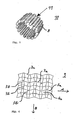
- FIG. 1 An acoustic absorber 10 is shown as a preferred embodiment of the invention.
- the acoustic absorber 10 has a honeycomb-shaped, 3-dimensional structure 11.
- the honeycomb structure 11 forms a curved core whose shape is designed for use in the inlet of engines.
- the honeycomb 3-dimensional structure 11 is curved so as to form a ring. That is, the wall of the ring consists of the 3-dimensional honeycomb structure 11th
- the structure or honeycomb structure 11 comprises a plurality of folding honeycomb 8, which are formed by folding a flat semi-finished product.
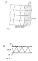
- a flat semi-finished product 9 is shown, from which the folding honeycomb 8 of the absorber 11 (s. Fig. 1 ) are formed by folding.
- the semi-finished product 9 has for this purpose a defined suitable folding pattern, which consists of a plurality of fold lines 3a, 3b, which extend in a zigzag manner in two substantially perpendicular to each other main directions A, B.
- the fold lines 3a along the main direction A and the fold lines 3b along the main direction B each extend substantially parallel to each other.
- geometric patterns in the form of trapezoids are formed in the flat or 2-dimensional semi-finished product 9, which repeat themselves regularly.
- the patterns 4a are designed such that, when the flat semi-finished product 9 is folded along the folding lines 3a, 3b, the folding honeycombs 8 (see FIG Fig. 1 ) form. That is, due to the defined geometric folding pattern by keeping the level or 2-dimensional semi-finished product, a 3-dimensional honeycomb structure with folded honeycomb arises, which is initially designed plate-like and has a thickness which is defined by the size of the individual folding honeycomb 8 or honeycomb elements.
- the folding honeycomb 8 of in Fig. 1 The cores shown act as resonators for the sound waves to be absorbed and are accordingly designed in size and geometry according to the respective requirements.
- a flat, thin material is provided with folds in different directions, which are formed from a plurality of zigzag folding lines.
- the individual surface elements of the folded honeycomb may be, for example, parallelograms, trapezoids, triangles, etc., or a combination of various geometric shapes.
- Fig. 5 shows a flat semi-finished product 19, wherein the partial surfaces 7a are perforated.
- the flat semi-finished product 19 corresponds to the flat semi-finished product 9 (see FIG Fig. 4 ) already described above.
- the perforation of the partial surfaces 7a further simplifies the production of the absorber elements and avoids the known positioning problems.
- 3-dimensional honeycomb structures are formed, which are plate-like and have a plate thickness, which is defined by the size of the individual folding honeycomb.
- the honeycomb structures are then curved so that they are adapted to a given 3-dimensionally shaped surface.
- the individual folds which are predetermined by the folding lines 3a, 3b in the flat semi-finished product 9, 19, are flexible and allow an adaptation of the folding angles when the 3-dimensional honeycomb structure 11 is curved. That is, the individual folding honeycomb 8 (s. Fig. 1 ) are not rigid due to their production by folding the flat semi-finished product 9, 19 but flexible and allow an adjustment of the angle between individual wall elements of the folding honeycomb. 8
- the curved honeycomb structures 11, for example, are provided with one or more cover layers, e.g. perforated and can be arranged on both sides of the honeycomb structure 11.
- cover layers e.g. perforated and can be arranged on both sides of the honeycomb structure 11.
- different honeycomb structures 11 can be prepared and arranged overlapping or interlocked to form any absorber in size and geometry, especially for aircraft engines.
- honeycomb structures e.g. are formed from the semifinished product 19 with the perforated partial surfaces 7a, are arranged one above the other, with no additional middle layer with perforations is necessary, since the perforations are already applied to the partial surfaces 7a of the still unfolded semi-finished product 9.
- This creates a broadband acting 2-DOF absorber which is relatively inexpensive and accurate to produce.
- the size of the volume of the individual folding honeycomb 8 and its extent or depth is determined by the respective Faltgeometrien and can be varied over the inlet depth of the engine and over the circumference. This achieves a particularly effective sound absorption in the engine with an increased bandwidth.
- Fig. 6 shows a section through an absorber 12 with a honeycomb structure of folded honeycomb 28, which between a reserve 27 and a perforated cover layer 30th is arranged.
- the folding honeycomb 28 are formed from the semifinished product by folding as described above.
- a 2-DOF absorber In the honeycomb structure resulting from the design of the folded honeycomb two separate volume areas, so that there is only a honeycomb structure layer, a 2-DOF absorber.
- Multiple absorbers 12 may be stacked to form multi-dimensional absorbers, for example, 4-DOF, 6-DOF, 8-DOF absorbers, etc., with the honeycomb layers each separated by a perforated layer 30.
- a coupling of adjacent chambers or folded honeycomb 8 or 27, 28 can be achieved selectively and in a simple manner.
- the folding of the perforated semifinished products e.g. Ventilated core structures are also possible, that is, honeycomb 3-dimensional structures 11 are created in which individual areas or honeycombs are selectively coupled or ventilated by perforations.
Landscapes
- Engineering & Computer Science (AREA)
- Chemical & Material Sciences (AREA)
- Combustion & Propulsion (AREA)
- Mechanical Engineering (AREA)
- General Engineering & Computer Science (AREA)
- Physics & Mathematics (AREA)
- Acoustics & Sound (AREA)
- Multimedia (AREA)
- Soundproofing, Sound Blocking, And Sound Damping (AREA)
- Exhaust Silencers (AREA)
- Laminated Bodies (AREA)
- Vehicle Interior And Exterior Ornaments, Soundproofing, And Insulation (AREA)
Description
- Die vorliegende Erfindung betrifft einen akustischen Absorber, der insbesondere für Triebwerke von Flugzeugen geeignet ist und eine wabenartig geformte, 3-dimensionale Struktur aufweist, die beim Einsatz in einem Triebwerk Lärm des Triebwerks absorbiert. Weiterhin betrifft die Erfindung eine besondere Verwendung von Faltwaben.
- Triebwerke allgemein und insbesondere Triebwerke von Flugzeugen haben das Problem einer starken Geräuschentwicklung. Insbesondere bei Triebwerken mit großem Nebenstromverhältnis findet eine starke Geräuschentwicklung im Triebwerkseinlauf statt. Durch Blattspitzengeschwindigkeiten oberhalb von Mach1 werden z. B. Schockwellen erzeugt, die zur Anregung von akustischen Eigenmoden im Einlaufkanal führen. Diese Moden strahlen sehr effektiv nach außen ab und führen zu einem sehr lauten Geräusch. Dieser Lärm, der auch "buzz-saw-noise" genannt wird, wird während der Startphase eines Flugzeugs in der Umgebung des Flughafens besonders stark wahrgenommen. Der Lärm dringt aber auch in die Passagierkabine des Flugzeuges selbst und wird von den Passagieren besonders in der vorderen Sektion wahrgenommen. Weitere Lärmanteile treten bei der Blattfolgefrequenz des Bläsers bzw. Fans sowie deren Harmonischen auf und Breitbandlärm sowie Anteile aus anderen Triebwerksstufen wie z. B. Verdichter, sind ebenfalls zu berücksichtigen.
- Um dieses Geräusch im Einlauf- oder Nebenstromkanal von Triebwerken zu bekämpfen, werden üblicherweise absorbierende Flächen als passive Schallabsorber im Bereich des Triebwerkeinlaufs angebracht. Dabei werden vorwiegend sogenannte "single degree of freedom" bzw. SDOF-Absorber eingesetzt, die im wesentlichen aus einer Honigwabenstruktur bestehen, die mit einem Lochblech oder einem feinmaschigen Drahtgeflecht abgedeckt sind. Die Honigwabenstruktur wirkt als Resonator, wobei die Bautiefe der Honigwabenstruktur an die Wellenlänge angepasst ist und ein Viertel der Wellenlänge beträgt. Derartige SDOF-Absorber sind daher besonders wirksam bei dieser Resonanzfrequenz.
- Um eine breitbandigere Dämpfung von Lärm zu ermöglichen, wurden Absorber entwickelt, die aus zwei oder drei hintereinander geschalteten SDOF-Absorbern bestehen. Derartige Absorber werden auch 2-DOF-Absorber bzw. 3-DOF-Absorber genannt. Weiterhin wurde versucht, Absorber verschiedener Bautiefe parallel zu schalten.
- Zur Veranschaulichung zeigt
Fig. 2a einen bekannten SDOF-Absorber mit einer Vielzahl von Honigwaben 1, die zwischen einer unteren Decklage 2 und einer oberen Decklage 3 angeordnet sind.Fig. 2b zeigt einen bekannten 2-DOF-Absorber mit zwei übereinander liegenden Schichten von Honigwaben 1a, 1b unter der Decklage 3. - Bei den bekannten Absorbern besteht das Problem, dass großflächige, gekrümmte Strukturen nur auf sehr komplizierte Weise gefertigt werden können, was mit hohen Kosten verbunden ist. Derzeitige Honigwabenkern-Absorber in Triebwerken haben den besonderen Nachteil, dass sie nicht die gesamte Fläche des Einlaufs bedecken. Eine Ursache hierfür ist der sogenannte Satteleffekt, der dazu führt, dass die Honigwaben nicht beliebig gekrümmt werden können. Daher wird die effektive Fläche nicht ausgenutzt und der Lärm im Triebwerkseinlauf kann nicht ausreichend absorbiert bzw. reduziert werden.
- Zur Veranschaulichung zeigen die
Figuren 3a und 3b den Satteleffekt. Beim Versuch, die eben ausgebildete Honigwabenstruktur gemäßFigur 3a zu krümmen, entsteht aufgrund der Geometrie der Waben eine sattelartige Struktur mit einem ersten bzw. inneren Krümmungsradius p1 und einem zweiten Krümmungsradius p2, der eine sattelartige Vertiefung der Wabenstruktur bildet. - Zusätzlich besteht das Problem, dass die Honigwaben nicht miteinander verzahnt werden können, was eine nahtlose Fertigung weiter erschwert. Weiterhin können die Honigwaben aufgrund ihres Fertigungsverfahrens nicht präzise positioniert werden, wodurch z.B. notwendige Perforationslöcher in vielen Fällen überdeckt werden. Das gilt insbesondere für MDOF-Absorber (MDOF = multiple degree of freedom) mit mehreren Freiheitsgraden, die eine sehr genaue Positionierung der Zwischenlagen erfordern. D.h., die übereinanderliegenden Schichten von Honigwaben müssen besonders genau positioniert werden. Bei dieser Art von Absorbern kommt der oben erwähnte Satteleffekt besonders zum Tragen, da dieser eine seitliche Verschiebung der jeweiligen Wabe zu den Deck- und Zwischenlagen bewirkt.
- Bisher müssen MDOF-Absorber immer durch Sandwich-Konstruktionen mit mehreren Kernen hergestellt werden. Dadurch entstehen erhöhte Kosten und es ist eine sehr präzise Ausrichtung der Waben zu den perforierten Zwischenlagen erforderlich. Hinzu kommt, dass Honigwaben auf eine feste Zellgröße festgelegt sind. D.h., es lassen sich keine Absorberstrukturen mit variablen Volumina realisieren.
- Das Dokument
EP-0 314 261 offenbart einen akustischen Absorber mit einer Honigwabenanordnung, die eine Innenwand, eine Außenwand, die von der Innenwand beabstandet ist, um einen zwischen den Wänden angeordneten Raum zu bilden und eine Mehrzahl von gewellten Streifen, welche miteinander verschweißt sind und direkt an wenigstens der Innenwand befestigt sind, um Unterteilungen der Honigwabenanordnung zu bilden, besitzt. - Das Dokument
US-3,542,152 offenbart einen akustischen Absorber für Triebwerke mit einer Innenwand, einer Außenwand und dazwischen Zellen, die mit dem Luftstrom des Triebwerkes durch Öffnungen in Verbindung sind. - Das Dokument
US-5,028,474 offenbart eine wabenartig geformten 3-dimensionalen Struktur, wobei die Struktur Faltwaben umfasst, die durch Faltung eines ebenen Halbzeuges gebildet sind. - Das Dokument
WO2004/043685 offenbart ein Verfahren zur Herstellung einer Kernstruktur für einen Kernverbund, wobei die Kernstruktur aus einem dünnen faltbaren Ausgangsmaterial mit einer Undefinierten Länge, hergestellt wird. - Es ist die Aufgabe der vorliegenden Erfindung, einen akustischen Absorber zu schaffen, mit dem der Satteleffekt bei der Bildung von großflächigen, gekrümmten Strukturen vermieden wird. Der Absorber soll insbesondere für Triebwerke von Flugzeugen geeignet sein und vor allem in Triebwerkseinläufen eine hohe Präzision für die Absorberelemente ermöglichen.
- Diese Aufgabe wird gelöst durch den akustischen Absorber gemäß Patentanspruch 1. Weitere vorteilhafte Merkmale, Aspekte und Details der Erfindung ergeben sich aus den abhängigen Ansprüchen, der Beschreibung und den Zeichnungen.
- Der erfindungsgemäße akustische Absorber ist insbesondere für Triebwerke von Flugzeugen geeignet und hat eine wabenartig geformte 3-dimensionale Struktur, die beim Einsatz in einem Triebwerk Lärm des Triebwerks absorbiert, wobei die Struktur Faltwaben umfasst, die durch Faltung eines ebenen Halbzeuges gebildet sind, und darüberhinaus die weiteren Merkmale aus Anspruch 1 aufweist.
- Durch die Verwendung von Faltwaben, die durch Faltung eines ebenen Halbzeuges entstehen, können großflächige gekrümmte Strukturen als Absorber bzw. Absorberelemente gefertigt werden, wobei der Satteleffekt aufgrund der Geometrie der Faltungen vermieden wird. Insbesondere können Faltwaben aufgrund ihrer Konstruktionseigenschaften von vornherein auf gekrümmte 3-dimensionale Geometrien eingestellt werden. Durch die Faltung entstehen z.B. 3-dimensionale Kernstrukturen, die sich durch verschiedene Faltmuster beliebig einstellen lassen. Der fehlende Satteleffekt ermöglicht zudem eine genaue Positionierung des Kerns zu den Decklagen des Absorbers. Einzelne Absorberelemente, die aus Faltwaben gebildet sind, können problemlos miteinander verzahnt werden, was zu einer erhöhten Präzision führt.
- Die aus den Faltwaben gebildete Struktur ist eine 3-dimensionale Kernstruktur mit einem vorgegebenen Faltmuster. Durch verschiedenartige Faltmuster können beliebige Krümmungen des fertigen Absorbers bzw. Absorberelements erzielt werden. Dadurch kann eine exakte Anpassung und Positionierung vor allem in Triebwerken von Flugzeugen und insbesondere in den Triebwerkseinläufen erfolgen, die eine verbesserte Lärmabsorption zur Folge hat.
- Vorteilhafterweise überlappen sich mehrere der wabenartigen Strukturen gegenseitig. Sie können aber auch ineinander verzahnt sein. Dadurch wird eine höhere Präzision bei der Positionierung der Absorberelemente erzielt.
- Bevorzugt umfasst der akustische Absorber ein oder mehrere perforierte Flächen, wobei die perforierten Flächen aus Teilflächen des ebenen Halbzeuges gebildet sind. Dadurch wird der Aufwand bei der Herstellung noch weiter reduziert und damit die Kosten gesenkt. Gleichzeitig befinden sich die perforierten Flächen an den exakt vorgegebenen Positionen des Absorbers.
- Bevorzugt hat der akustische Absorber zwei räumlich voneinander getrennte Volumenbereiche, die durch die Faltwaben gebildet sind und auf unterschiedlichen bzw. entgegengesetzten Seiten des Absorbers ausgestaltet sind. D.h., dass z.B. Faltwaben-Kerne aufgrund ihrer grundlegenden Eigenschaften den Zwischenraum, der durch sie gebildet wird, in zwei Volumenbereiche teilen, wobei z.B. ein Volumenbereich an eine obere und ein anderer Volumenbereich an eine untere Decklage angrenzt. Dadurch können insbesondere mehrdimensionale Absorber, wie z.B. 2-DOF-Absorber, besonders einfach und kostengünstig gefertigt werden. Die Perforation und die Positionierung der mittleren Schicht, die bei bisherigen MDOF-Absorbern notwendig ist, entfallen. Statt dessen kann die Perforation auf die Flächen des ungefalteten ebenen Halbzeuges aufgebracht werden, d.h. vor der Faltung und Bildung der Faltwaben. Dadurch wird ein sehr exaktes und variables Design von 2-DOF-Absorbern bzw. 2-DOF-Systemen ermöglicht.
- Die Faltwaben weisen ein oder mehrere vorgegebene Faltgeometrien auf, die an den Umfang und an die Einlauftiefe des jeweiligen Triebwerks angepasst oder anpassbar sind. D.h., durch die unterschiedlichen Faltgeometrien ist es möglich, die Volumengröße und -tiefe der Faltwaben über den Umfang und Einlauftiefe zu variieren. Dadurch wird eine noch weitere Flexibilität in der Auslegung des Absorbers erreicht.
- Aufgrund der Möglichkeit, bestimmte Faltmuster einzustellen bzw. zu wählen, aus denen die Faltwaben gebildet werden, sind z.B. auch belüftbare Kernstrukturen oder eine Kopplung benachbarter Kammern möglich.
- Zusätzlich ist es mit den Faltwaben möglich, getrennt hergestellte Wabenstrukturen zu überlappen und einfach ineinander zu verzahnen, wodurch eine annähernd nahtlose Konstruktion ermöglicht wird.
- Gemäß einem Aspekt der Erfindung werden Faltwaben, die durch Faltung eines ebenen Halbzeugs gebildet sind, als akustisches Absorberelement, insbesondere für Triebwerke von Flugzeugen, verwendet. Dabei sind die Faltwaben vorteilhafterweise in ihrer Geometrie derart ausgelegt, dass sie zur Absorption von Triebwerkslärm von Flugzeugen geeignet sind. Die Faltwaben werden insbesondere zur Bildung bzw. Herstellung eines erfindungsgemäßen akustischen Absorbers verwendet.
- Vorteile und Merkmale, die im Zusammenhang mit dem erfindungsgemäßen akustischen Absorber genannt sind, gelten auch für die besondere Verwendung von Faltwaben gemäß der vorliegenden Erfindung.
- Nachfolgend wird die Erfindung beispielhaft anhand der Figuren erläutert, in denen
- Fig. 1
- eine Ansicht eines akustischen Absorbers gemäß einer bevorzugten Ausführungsform der Erfindung zeigt, der als gekrümmter Kern ausgestaltet ist;
- Fig. 2a und b
- einen SDOF-Absorber und einen 2-DOF-Absorber gemäß dem Stand der Technik zeigen;
- Fig. 3a und b
- eine Ansicht einer Honigwabenstruktur eines bekannten akustischen Absorbers im ebenen Zustand (
Fig. 3a ) und im gekrümmten Zustand (Fig. 3b ) zur Darstellung des Satteleffektes zeigt; - Fig. 4
- ein ebenes Faltmuster zur Bildung des in
Fig. 1 gezeigten Kerns zeigt; - Fig. 5
- eine Ansicht eines Faltmusters auf einem ebenen Halbzeug mit perforierten Teilflächen zeigt, aus dem der erfindungsgemäße akustische Absorber gebildet wird; und
- Fig. 6
- einen Absorber mit einer Schicht von Faltwaben in einer Schnittansicht zeigt.
- In
Fig. 1 ist ein akustischer Absorber 10 als bevorzugte Ausführungsform der Erfindung dargestellt. Der akustische Absorber 10 weist eine wabenartig geformte, 3-dimensionale Struktur 11 auf. Die Wabenstruktur 11 bildet einen gekrümmten Kern, dessen Form zum Einsatz im Einlauf von Triebwerken ausgestaltet ist. Zu diesem Zweck ist die wabenartige 3-dimensionale Struktur 11 derart gekrümmt, dass sie einen Ring bildet. D.h., die Wandung des Ringes besteht aus der 3-dimensionalen Wabenstruktur 11. - Die Struktur bzw. Wabenstruktur 11 umfasst eine Vielzahl von Faltwaben 8, die durch Faltung eines ebenen Halbzeuges gebildet sind.
- In
Fig. 4 ist ein ebenes Halbzeug 9 dargestellt, aus dem die Faltwaben 8 des Absorbers 11 (s.Fig. 1 ) durch Faltung gebildet sind. Das Halbzeug 9 hat zu diesem Zweck ein definiertes geeignetes Faltmuster, das aus einer Vielzahl von Faltlinien 3a, 3b besteht, die zickzackartig in zwei im wesentlichen senkrecht zueinander gerichteten Hauptrichtungen A, B verlaufen. Die Faltlinien 3a entlang der Hauptrichtung A und die Faltlinien 3b entlang der Hauptrichtung B verlaufen dabei jeweils im wesentlichen parallel zueinander. Durch den Verlauf der Faltlinien 3a, 3b werden in dem ebenen bzw. 2-dimensionalen Halbzeug 9 geometrische Muster in Form von Trapezen gebildet, die sich regelmäßig wiederholen. Dabei sind die Muster 4a derart gestaltet, dass sich bei einer geeigneten Faltung des ebenen Halbzeugs 9 entlang der Faltlinien 3a, 3b die Faltwaben 8 (sieheFig. 1 ) bilden. D.h., dass aufgrund des definierten geometrischen Faltmusters durch Haltung des ebenen bzw. 2-dimensionalen Halbzeuges eine 3-dimensionale Wabenstruktur mit Faltwaben entsteht, die zunächst plattenartig ausgestaltet ist und eine Dicke aufweist, die durch die Größe der einzelnen Faltwaben 8 bzw. Wabenelemente definiert ist. - Die Faltwaben 8 des in
Fig. 1 gezeigten Kerns wirken als Resonatoren für die zu absorbierenden Schallwellen und sind dementsprechend in ihrer Größe und Geometrie entsprechend den jeweiligen Anforderungen ausgestaltet. - Die Fertigung von Faltwaben durch Faltung ist als solche bekannt und beispielsweise in dem
US-Patent Nr. 2,950,656 und in demUS-Patent Nr. 5,947,885 im Detail beschrieben. Erfindungsgemäß wird dieses Verfahren zur Bildung des akustischen Absorbers 10 ohne Satteleffekt verwendet. - Zur Bildung der Faltwaben 8 wird ein flaches, dünnes Material mit Falzen in verschiedenen Richtungen versehen, die aus einer Vielzahl von zickzackartigen Faltlinien gebildet sind. Die einzelnen Flächenelemente der Faltwaben können beispielsweise Parallelogramme, Trapeze, Dreiecke, usw. sein, oder eine Kombination verschiedenartiger geometrischer Formen.
-
Fig. 5 zeigt ein ebenes Halbzeug 19, bei dem Teilflächen 7a perforiert sind. Hinsichtlich der weiteren Merkmale entspricht das ebene Halbzeug 19 dem ebenen Halbzeug 9 (sieheFig. 4 ), das oben bereits beschrieben ist. Durch die Perforation der Teilflächen 7a wird die Herstellung der Absorberelemente noch weiter vereinfacht und es werden die bekannten Probleme bei der Positionierung vermieden. - Nach der Faltung der in den
Figuren 4 und5 gezeigten ebenen Halbzeuge 9 bzw. 19 entstehen 3-dimensionale Wabenstrukturen, die plattenartig geformt sind und eine Plattendicke aufweisen, die durch die Größe der einzelnen Faltwaben definiert ist. Die Wabenstrukturen werden anschließend gekrümmt, so dass sie an eine vorgegebene 3-dimensional geformte Fläche angepasst sind. Bei der Krümmung der Faltwaben, z.B. zur Bildung des inFig. 1 gezeigten ringartigen Kerns, entstehen aufgrund der besonderen Wabengeometrie keine unerwünschten Spannungen, so dass der bekannte Satteleffekt vermieden wird. Die einzelnen Falze, die durch die Faltlinien 3a, 3b in dem ebenen Halbzeug 9, 19 vorgegeben sind, sind flexibel und erlauben eine Anpassung der Faltwinkel, wenn die 3-dimensionale Wabenstruktur 11 gekrümmt wird. D.h., die einzelnen Faltwaben 8 (s.Fig. 1 ) sind aufgrund ihrer Herstellung durch Faltung des ebenen Halbzeugs 9, 19 nicht starr, sondern flexibel und erlauben eine Anpassung der Winkel zwischen einzelnen Wandelementen der Faltwaben 8. - Je nach den Erfordernissen des Einzelfalls werden die beispielsweise gekrümmten Wabenstrukturen 11 zum Beispiel mit ein oder mehreren Decklagen versehen, die z.B. perforiert sind und beidseitig der Wabenstruktur 11 angeordnet sein können. Bei der Gestaltung des Absorbers mit Faltwaben können verschiedene Wabenstrukturen 11 hergestellt werden und überlappend oder ineinander verzahnt angeordnet werden, um in Größe und Geometrie beliebige Absorber, insbesondere für Flugzeugtriebwerke, zu bilden.
- Es können mehrere Wabenstrukturen, die z.B. aus dem Halbzeug 19 mit den perforierten Teilflächen 7a gebildet sind, übereinander angeordnet werden, wobei keine zusätzliche mittlere Schicht mit Perforationen notwendig ist, da die Perforationen bereits auf den Teilflächen 7a des noch ungefalteten Halbzeuges 9 aufgebracht sind. Dadurch entsteht ein breitbandig wirkender 2-DOF-Absorber, der relativ kostengünstig und exakt herstellbar ist. Die Größe der Volumen der einzelnen Faltwaben 8 und deren Ausdehnung bzw. Tiefe wird durch die jeweiligen Faltgeometrien bestimmt und kann über die Einlauftiefe des Triebwerks und über den Umfang variiert werden. Dadurch wird eine besonders wirksame Schallabsorption im Triebwerk mit einer erhöhten Bandbreite erzielt.
-
Fig. 6 zeigt einen Schnitt durch einen Absorber 12 mit einer Wabenstruktur aus Faltwaben 28, die zwischen einer Rücklage 27 und einer perforierten Decklage 30 angeordnet ist. Die Faltwaben 28 sind wie oben beschrieben aus dem Halbzeug durch Faltung gebildet. In der Wabenstruktur ergeben sich durch die Ausgestaltung der Faltwaben zwei voneinander getrennte Volumenbereiche, so dass mit nur einer Wabenstrukturschicht ein 2-DOF-Absorber vorliegt. - Mehrere Absorber 12 können zur Bildung mehrdimensionaler Absorber, zum Beispiel 4-DOF-, 6-DOF-, 8-DOF-Absorber usw., übereinander gestapelt werden, wobei die Wabenstruktur-Schichten jeweils durch eine perforierte Schicht 30 voneinander getrennt sind.
- Durch die vorgegebenen Perforationen, die bereits im ebenen Halbzeug 19 vorgesehen sind, kann gezielt und auf einfache Weise eine Kopplung benachbarter Kammern bzw. Faltwaben 8 bzw. 27, 28 erreicht werden. Weiterhin sind durch die Faltung der perforierten Halbzeuge z.B. auch belüftete Kernstrukturen möglich, d.h., es werden wabenartige 3-dimensionale Strukturen 11 geschaffen, bei denen gezielt einzelne Bereiche bzw. Waben durch Perforationen miteinander gekoppelt bzw. belüftet sind.
Claims (7)
- Akustischer Absorber für Triebwerke von Flugzeugen, mit einer wabenartig geformten 3-dimensionalen Struktur (11; 12), die beim Einsatz in einem Triebwerk Lärm des Triebwerkes absorbiert, wobei die Struktur (11; 12) Faltwaben (8; 28) umfasst, die durch Faltung eines ebenen Halbzeuges (9; 19) gebildet sind, und wobei die 3-dimensionale Struktur aus einem einzigen Halbzeug gebildet wird, und wobei das Halbzeug (9, 19) aus einer Vielzahl von ebenen, in zwei Hauptrichtungen (A, B) aneinander angrenzenden Flächenelementen (4a, 7a) besteht, die mittels Faltlinien (3a, 3b) gegeneinander abgegrenzt sind, und durch Faltung entlang der Faltlinien (3a, 3b) eine großflächige Wabenstruktur mit einer Vielzahl von hintereinander liegenden Wabenreihen gebildet ist,
dadurch gekennzeichnet, dass die Größe der Volumen der einzelnen Faltwaben und deren Ausdehnung durch die jeweiligen Faltgeometrien bestimmt wird und über die Einlauftiefe des Triebwerks und den Umfang variiert wird. - Akustischer Absorber nach Anspruch 1, dadurch gekennzeichnet, dass ein erster Satz Faltlinien (3a) in einer Hauptrichtung (A) abschnittsweise zueinander parallel verlaufen und ein zweiter Satz Faltlinien (3b) in einer zweiten Hauptrichtung (B) zickzackartig verlaufen.
- Akustischer Absorber nach Anspruch 1, dadurch gekennzeichnet, dass die Flächenelemente (4a, 7a) Parallelogramme, Trapeze und/oder Dreiecke sind.
- Akustischer Absorber nach einem der vorhergehenden Ansprüche, dadurch gekennzeichnet, dass sich mehrere der wabenartigen Strukturen (11 ; 12) gegenseitig überlappen und/oder ineinander verzahnt sind.
- Akustischer Absorber nach einem der vorhergehenden Ansprüche, gekennzeichnet durch ein oder mehrere perforierte Flächen (30), die aus Teilflächen (7a) des ebenen Halbzeuges (19) gebildet sind.
- Akustischer Absorber nach einem der vorhergehenden Ansprüche, gekennzeichnet durch mindestens zwei räumlich getrennte Volumenbereiche, die durch die Faltwaben (8; 28) gebildet und auf unterschiedlichen Seiten des Absorbers ausgestaltet sind.
- Akustischer Absorber nach Anspruch 6, gekennzeichnet durch eine obere und/oder eine untere Decklage (30), an die jeweils einer der Volumenbereiche angrenzt.
Applications Claiming Priority (2)
| Application Number | Priority Date | Filing Date | Title |
|---|---|---|---|
| DE102004053383A DE102004053383A1 (de) | 2004-11-02 | 2004-11-02 | Akustischer Absorber für Flugtriebwerke |
| PCT/DE2005/001936 WO2006047991A1 (de) | 2004-11-02 | 2005-10-28 | Akustischer absorber für flugtriebwerke |
Publications (2)
| Publication Number | Publication Date |
|---|---|
| EP1807616A1 EP1807616A1 (de) | 2007-07-18 |
| EP1807616B1 true EP1807616B1 (de) | 2015-05-27 |
Family
ID=35788433
Family Applications (1)
| Application Number | Title | Priority Date | Filing Date |
|---|---|---|---|
| EP05806861.0A Expired - Lifetime EP1807616B1 (de) | 2004-11-02 | 2005-10-28 | Akustischer absorber für flugtriebwerke |
Country Status (9)
| Country | Link |
|---|---|
| US (1) | US8302733B2 (de) |
| EP (1) | EP1807616B1 (de) |
| JP (1) | JP2008519190A (de) |
| CN (1) | CN101076659A (de) |
| BR (1) | BRPI0517242A (de) |
| CA (1) | CA2583103C (de) |
| DE (1) | DE102004053383A1 (de) |
| RU (1) | RU2392462C2 (de) |
| WO (1) | WO2006047991A1 (de) |
Cited By (1)
| Publication number | Priority date | Publication date | Assignee | Title |
|---|---|---|---|---|
| US12168564B2 (en) | 2019-12-23 | 2024-12-17 | 3M Innovative Properties Company | Multi-slit tension-activated, expanding sheets |
Families Citing this family (35)
| Publication number | Priority date | Publication date | Assignee | Title |
|---|---|---|---|---|
| FR2912780B1 (fr) * | 2007-02-20 | 2012-03-02 | Airbus France | Revetement pour le traitement acoustique incorporant une structure alveolaire avec une forme complexe |
| WO2008104716A2 (fr) * | 2007-02-20 | 2008-09-04 | Airbus France | Procede de realisation d ' un revetement pour le traitement acoustique et revetement ainsi obtenu |
| FR2922152B1 (fr) | 2007-10-16 | 2009-11-20 | Aircelle Sa | Structure a ame alveolaire pour panneau acoustique |
| US8459407B2 (en) * | 2008-10-01 | 2013-06-11 | General Electric Company | Sound attenuation systems and methods |
| FR2944470B1 (fr) * | 2009-04-16 | 2011-04-01 | Aircelle Sa | Panneau alveolaire |
| WO2011036575A2 (en) * | 2009-09-25 | 2011-03-31 | Schlumberger Canada Limited | Multi-layered sound attenuation mechanism |
| DE102011008922A1 (de) | 2011-01-19 | 2012-07-19 | Rolls-Royce Deutschland Ltd. & Co. Kg | Verfahren zur Herstellung eines Schallabsorbers, insbesondere für einen Gasturbinenabgaskonus |
| US9623952B1 (en) * | 2011-03-11 | 2017-04-18 | The United States Of America As Represented By The Administrator Of The National Aeronautics And Space Administration | External acoustic liners for multi-functional aircraft noise reduction |
| US9227719B2 (en) | 2011-03-11 | 2016-01-05 | The United States Of America As Represented By The Administrator Of The National Aeronautics And Space Administration | Reactive orthotropic lattice diffuser for noise reduction |
| DE102011120979A1 (de) | 2011-12-13 | 2013-06-13 | Rolls-Royce Deutschland Ltd & Co Kg | Akustischer Absorber |
| US8579076B2 (en) * | 2012-02-29 | 2013-11-12 | Hexcel Corporation | Splicing of curved acoustic honeycomb |
| GB201301702D0 (en) | 2013-01-31 | 2013-03-20 | Rolls Royce Plc | Exhaust cone |
| US8997923B2 (en) * | 2013-08-12 | 2015-04-07 | Hexcel Corporation | Sound wave guide for use in acoustic structures |
| US9068345B2 (en) * | 2013-08-12 | 2015-06-30 | Hexcel Corporation | Multi-sectional acoustic septum |
| US9284726B2 (en) * | 2014-04-04 | 2016-03-15 | The Boeing Company | Pyramid waffle core structure and method of fabrication |
| US9640164B2 (en) | 2015-02-27 | 2017-05-02 | The Boeing Company | Sound attenuation using a cellular core |
| US9469985B1 (en) * | 2015-05-11 | 2016-10-18 | Hexcel Corporation | Acoustic structures with multiple degrees of freedom |
| CN106606993B (zh) * | 2015-10-26 | 2018-12-21 | 中国石油化工集团公司 | 一种二氧化碳可溶两性离子表面活性剂及其制备方法 |
| US9725155B2 (en) * | 2015-12-30 | 2017-08-08 | General Electric Company | Method and system for open rotor engine fuselage protection |
| FR3047600B1 (fr) * | 2016-02-08 | 2018-02-02 | Universite Paris-Sud | Absorbeur acoustique, paroi acoustique et procede de conception et fabrication |
| GB201617840D0 (en) * | 2016-10-21 | 2016-12-07 | Rolls Royce Plc | Complementary structure |
| US10332501B2 (en) * | 2017-02-01 | 2019-06-25 | General Electric Company | Continuous degree of freedom acoustic cores |
| KR102273461B1 (ko) * | 2017-04-13 | 2021-07-07 | 현대자동차주식회사 | 음파투과형 금속판재 및 이를 이용한 흡음형 복합판재 |
| US11059559B2 (en) * | 2018-03-05 | 2021-07-13 | General Electric Company | Acoustic liners with oblique cellular structures |
| US11047304B2 (en) | 2018-08-08 | 2021-06-29 | General Electric Company | Acoustic cores with sound-attenuating protuberances |
| US11359577B2 (en) | 2018-08-22 | 2022-06-14 | Rohr, Inc. | Multi-degree of freedom acoustic panel |
| FR3093025B1 (fr) * | 2019-02-26 | 2023-03-24 | Safran Nacelles | Système alvéolaire dilatable pour panneau sandwich |
| WO2021018903A1 (en) * | 2019-07-30 | 2021-02-04 | Low & Bonar B.V. | Underlayment |
| CA3165868A1 (en) | 2019-12-23 | 2021-07-01 | 3M Innovative Properties Company | Tension-activated, expanding sheets |
| CN114074753A (zh) * | 2020-08-19 | 2022-02-22 | 中国航发商用航空发动机有限责任公司 | 蜂窝件及其制造方法、蜂窝装置、声衬和航空发动机 |
| US11715450B2 (en) | 2020-12-22 | 2023-08-01 | Rohr, Inc. | Acoustic panel core cell with funnel shaped septum |
| US11965465B2 (en) | 2020-12-22 | 2024-04-23 | Rohr, Inc. | Acoustic panel with multiple layer corrugated core |
| US11869472B2 (en) | 2021-08-02 | 2024-01-09 | Rohr, Inc. | Acoustic panel with reconfigurable chamber constrictions |
| EP4206448B1 (de) | 2022-01-04 | 2025-07-09 | Rohr, Inc. | Mehrkernige akustikplatte für ein flugzeugantriebssystem |
| US12163472B2 (en) | 2022-09-02 | 2024-12-10 | Rohr, Inc. | Engine exhaust nozzle with acoustic attenuation |
Citations (2)
| Publication number | Priority date | Publication date | Assignee | Title |
|---|---|---|---|---|
| US5028474A (en) * | 1989-07-25 | 1991-07-02 | Czaplicki Ronald M | Cellular core structure providing gridlike bearing surfaces on opposing parallel planes of the formed core |
| WO2004043685A2 (de) * | 2002-11-14 | 2004-05-27 | Airbus Deutschland Gmbh | Verfahren zur herstellung einer kernstruktur für einen kernverbund |
Family Cites Families (38)
| Publication number | Priority date | Publication date | Assignee | Title |
|---|---|---|---|---|
| US2771164A (en) * | 1949-01-27 | 1956-11-20 | Western Engineering Associates | Wall construction |
| US3992162A (en) * | 1955-06-09 | 1976-11-16 | Marc Wood International, Inc. | Sheet with alternate protrusions and recesses |
| US2950656A (en) * | 1958-01-16 | 1960-08-30 | Wood Marc Sa | Arrangement for the mechanical and continuous production of developable herring-bone structures |
| US3542152A (en) * | 1968-04-08 | 1970-11-24 | Gen Electric | Sound suppression panel |
| US3734234A (en) * | 1971-11-08 | 1973-05-22 | Lockheed Aircraft Corp | Sound absorption structure |
| SU415177A1 (de) | 1971-12-28 | 1974-02-15 | ||
| US3948346A (en) * | 1974-04-02 | 1976-04-06 | Mcdonnell Douglas Corporation | Multi-layered acoustic liner |
| US3960236A (en) * | 1974-06-17 | 1976-06-01 | Mcdonnell Douglas Corporation | Lock core panel |
| US4197341A (en) * | 1977-03-04 | 1980-04-08 | Hexcel Corporation | Cellular core structural panel components, structural panel formed therefrom and method of making |
| US4421811A (en) * | 1979-12-21 | 1983-12-20 | Rohr Industries, Inc. | Method of manufacturing double layer attenuation panel with two layers of linear type material |
| US4475624A (en) * | 1981-07-27 | 1984-10-09 | Ltv Aerospace And Defense Company | Honeycomb structure |
| US4632862A (en) * | 1985-03-01 | 1986-12-30 | Mullen Stephen J | I-beam honeycomb material |
| US4642993A (en) * | 1985-04-29 | 1987-02-17 | Avco Corporation | Combustor liner wall |
| US4832999A (en) * | 1987-10-27 | 1989-05-23 | Avco Lycoming/Textron | Honeycomb structure assemblies |
| GB8830057D0 (en) * | 1988-12-23 | 1989-02-22 | Lucas Ind Plc | An electrical connection arrangement and a method of providing an electrical connection |
| US5041323A (en) * | 1989-10-26 | 1991-08-20 | Rohr Industries, Inc. | Honeycomb noise attenuation structure |
| JP2674714B2 (ja) * | 1990-04-13 | 1997-11-12 | 新日本製鐵株式会社 | ハニカムコアおよびハニカムコアとハニカムパネルの製造方法 |
| RU1830326C (ru) | 1990-07-10 | 1993-07-30 | Казанский Авиационный Институт Им.А.Н.Туполева | Способ изготовлени многослойной панели криволинейной формы с зигзагообразным гофрированным заполнителем |
| US5126183A (en) | 1990-10-09 | 1992-06-30 | Lansing Overhaul And Repair, Inc. | Curved paneling including honeycomb core material having crimps in one edge |
| US5064493A (en) * | 1990-10-09 | 1991-11-12 | Lansing Overhaul And Repair, Inc. | Method of producing curved honeycomb core material having crimps in one edge |
| US5156183A (en) * | 1991-09-18 | 1992-10-20 | Scaramucci John P | Top-entry check valve having spring retainer |
| RU2064691C1 (ru) * | 1992-05-05 | 1996-07-27 | Товарищество с ограниченной ответственностью "Аэрос" | Звукопоглощающая конструкция |
| US5389059A (en) * | 1992-07-22 | 1995-02-14 | Corwin; Charles H. | Honeycomb structural material |
| US5292027A (en) * | 1992-10-05 | 1994-03-08 | Rockwell International Corporation | Tension and compression extensible liner for a primary vessel |
| US5431980A (en) * | 1993-02-01 | 1995-07-11 | Mccarthy; Daniel J. | Formable cellular material with synclastic behavior |
| US5310586A (en) * | 1993-02-05 | 1994-05-10 | Eldim, Inc. | Angled I-beam honeycomb structure |
| EP0636780A1 (de) * | 1993-06-25 | 1995-02-01 | Nordam | Lärmdämpfende Auskleidung für Strahlmotoren |
| DE4326189A1 (de) * | 1993-08-04 | 1995-02-16 | Steuler Industriewerke Gmbh | Wabenförmiger Hohlkörper aus Kunststoff, vorzugsweise Polyolefinen |
| US5380579A (en) * | 1993-10-26 | 1995-01-10 | Accurate Tool Company, Inc. | Honeycomb panel with interlocking core strips |
| US5947885A (en) * | 1994-11-01 | 1999-09-07 | Paterson; James G. T. | Method and apparatus for folding sheet materials with tessellated patterns |
| DE19606195A1 (de) | 1996-02-21 | 1998-09-10 | Pflug Jochen Dipl Ing Fh | Faltwabe |
| US5923003A (en) * | 1996-09-09 | 1999-07-13 | Northrop Grumman Corporation | Extended reaction acoustic liner for jet engines and the like |
| KR100322253B1 (ko) * | 1998-06-02 | 2002-05-13 | 위성갑 | 허니콤-발포알루미늄방음벽용패널 |
| CA2347844C (en) * | 1998-10-24 | 2007-03-06 | K.U. Leuven Research & Development | Thermoplastic folded honeycomb and process for its production |
| US6182787B1 (en) * | 1999-01-12 | 2001-02-06 | General Electric Company | Rigid sandwich panel acoustic treatment |
| US20030098200A1 (en) * | 2001-11-29 | 2003-05-29 | Allied International Corporation | Acoustical absorptive splitter |
| US6871725B2 (en) * | 2003-02-21 | 2005-03-29 | Jeffrey Don Johnson | Honeycomb core acoustic unit with metallurgically secured deformable septum, and method of manufacture |
| JP4506184B2 (ja) | 2004-02-05 | 2010-07-21 | 栗田工業株式会社 | 高含水比泥土の処理方法、高含水比泥土処理剤および高含水比泥土からの粒状処理土製造方法 |
-
2004
- 2004-11-02 DE DE102004053383A patent/DE102004053383A1/de not_active Ceased
-
2005
- 2005-10-28 BR BRPI0517242-0A patent/BRPI0517242A/pt not_active Application Discontinuation
- 2005-10-28 CN CNA2005800377492A patent/CN101076659A/zh active Pending
- 2005-10-28 CA CA2583103A patent/CA2583103C/en not_active Expired - Fee Related
- 2005-10-28 US US11/718,366 patent/US8302733B2/en not_active Expired - Lifetime
- 2005-10-28 WO PCT/DE2005/001936 patent/WO2006047991A1/de not_active Ceased
- 2005-10-28 RU RU2007120455/06A patent/RU2392462C2/ru not_active IP Right Cessation
- 2005-10-28 EP EP05806861.0A patent/EP1807616B1/de not_active Expired - Lifetime
- 2005-10-28 JP JP2007538269A patent/JP2008519190A/ja active Pending
Patent Citations (2)
| Publication number | Priority date | Publication date | Assignee | Title |
|---|---|---|---|---|
| US5028474A (en) * | 1989-07-25 | 1991-07-02 | Czaplicki Ronald M | Cellular core structure providing gridlike bearing surfaces on opposing parallel planes of the formed core |
| WO2004043685A2 (de) * | 2002-11-14 | 2004-05-27 | Airbus Deutschland Gmbh | Verfahren zur herstellung einer kernstruktur für einen kernverbund |
Cited By (1)
| Publication number | Priority date | Publication date | Assignee | Title |
|---|---|---|---|---|
| US12168564B2 (en) | 2019-12-23 | 2024-12-17 | 3M Innovative Properties Company | Multi-slit tension-activated, expanding sheets |
Also Published As
| Publication number | Publication date |
|---|---|
| RU2007120455A (ru) | 2008-12-10 |
| JP2008519190A (ja) | 2008-06-05 |
| BRPI0517242A (pt) | 2008-10-07 |
| US8302733B2 (en) | 2012-11-06 |
| WO2006047991A1 (de) | 2006-05-11 |
| RU2392462C2 (ru) | 2010-06-20 |
| EP1807616A1 (de) | 2007-07-18 |
| US20080223655A1 (en) | 2008-09-18 |
| CA2583103A1 (en) | 2006-05-11 |
| CN101076659A (zh) | 2007-11-21 |
| CA2583103C (en) | 2015-06-30 |
| DE102004053383A1 (de) | 2006-05-04 |
Similar Documents
| Publication | Publication Date | Title |
|---|---|---|
| EP1807616A1 (de) | Akustischer absorber für flugtriebwerke | |
| EP2846030B1 (de) | Schallabsorberanordnung | |
| DE60309112T2 (de) | Schalldämpfende Schicht für eine schalldämpfende Platte und eine Platte mit einer solchen Schicht | |
| DE69911331T2 (de) | Schalldämmende Wabenstruktur und Herstellungsverfahren | |
| DE60103352T2 (de) | Akustische Platte mit Sandwichaufbau | |
| DE2507743C2 (de) | Zusammengesetztes schallschluckendes Material in Sandwichausführung | |
| EP2406069B1 (de) | Mehrschichtplatte zur schalldämmung | |
| LU102779B1 (de) | Schalldämmendes Verbundbauteil mit Wabenkern und Herstellverfahren hierfür | |
| DE2513618C3 (de) | Filterstruktur aus porösem Folienwerkstoff | |
| DE102014218350A1 (de) | Schalldämpfende Anordnung für eine Triebwerksgondel und Triebwerksgondel mit einer solchen Anordnung | |
| EP1181421A1 (de) | Leichtbauelement in form einer hohlkörperkonturwabe | |
| DE2402877A1 (de) | Schallabsorbierende platte | |
| EP2032393B1 (de) | Strukturbauteil, insbesondere hitzeschild | |
| EP1724409B1 (de) | Flächiges Metallelement und Profilelement | |
| EP1886301B1 (de) | Sandwichstruktur mit frequenzselektivem doppelwandverhalten | |
| DE102007026296A1 (de) | Wabenkern, insbesondere für ein Sandwichbauteil, aus wenigstens zwei miteinander verbundenen Wabenkernteilen und Verfahren zu seiner Herstellung | |
| DE2234704A1 (de) | Wabenstruktur | |
| WO2016070976A1 (de) | Frontgassack | |
| DE102005027314A1 (de) | Verfahren zur Herstellung eines Leichtbaubleches | |
| DE602004004858T2 (de) | Schottwand für Flugzeug, die einen Frachtraum von einem Cockpit oder von einem Passagierraum trennt | |
| EP2114755B1 (de) | Leichtbaukonstruktion mit einer fraktal gegliederten stützstruktur | |
| DE102006025930A1 (de) | Rumpfstruktur und Verfahren zur Herstellung einer Rumpfstruktur | |
| DE102008062678B4 (de) | Verbundbauteil mit einer Wabenstruktur | |
| EP1597442B1 (de) | Zweischalige trennwand mit einer f llung aus mineralwolle | |
| EP0797486B1 (de) | Gitter, insbesondere flächiges gitter (gittermatte) |
Legal Events
| Date | Code | Title | Description |
|---|---|---|---|
| PUAI | Public reference made under article 153(3) epc to a published international application that has entered the european phase |
Free format text: ORIGINAL CODE: 0009012 |
|
| 17P | Request for examination filed |
Effective date: 20070522 |
|
| AK | Designated contracting states |
Kind code of ref document: A1 Designated state(s): AT BE BG CH CY CZ DE DK EE ES FI FR GB GR HU IE IS IT LI LT LU LV MC NL PL PT RO SE SI SK TR |
|
| DAX | Request for extension of the european patent (deleted) | ||
| 17Q | First examination report despatched |
Effective date: 20080306 |
|
| GRAP | Despatch of communication of intention to grant a patent |
Free format text: ORIGINAL CODE: EPIDOSNIGR1 |
|
| INTG | Intention to grant announced |
Effective date: 20150312 |
|
| GRAS | Grant fee paid |
Free format text: ORIGINAL CODE: EPIDOSNIGR3 |
|
| GRAA | (expected) grant |
Free format text: ORIGINAL CODE: 0009210 |
|
| AK | Designated contracting states |
Kind code of ref document: B1 Designated state(s): AT BE BG CH CY CZ DE DK EE ES FI FR GB GR HU IE IS IT LI LT LU LV MC NL PL PT RO SE SI SK TR |
|
| REG | Reference to a national code |
Ref country code: GB Ref legal event code: FG4D Free format text: NOT ENGLISH |
|
| REG | Reference to a national code |
Ref country code: CH Ref legal event code: EP |
|
| REG | Reference to a national code |
Ref country code: AT Ref legal event code: REF Ref document number: 728995 Country of ref document: AT Kind code of ref document: T Effective date: 20150615 |
|
| REG | Reference to a national code |
Ref country code: IE Ref legal event code: FG4D Free format text: LANGUAGE OF EP DOCUMENT: GERMAN |
|
| REG | Reference to a national code |
Ref country code: DE Ref legal event code: R096 Ref document number: 502005014806 Country of ref document: DE |
|
| REG | Reference to a national code |
Ref country code: FR Ref legal event code: PLFP Year of fee payment: 11 |
|
| REG | Reference to a national code |
Ref country code: LT Ref legal event code: MG4D |
|
| PG25 | Lapsed in a contracting state [announced via postgrant information from national office to epo] |
Ref country code: ES Free format text: LAPSE BECAUSE OF FAILURE TO SUBMIT A TRANSLATION OF THE DESCRIPTION OR TO PAY THE FEE WITHIN THE PRESCRIBED TIME-LIMIT Effective date: 20150527 Ref country code: LT Free format text: LAPSE BECAUSE OF FAILURE TO SUBMIT A TRANSLATION OF THE DESCRIPTION OR TO PAY THE FEE WITHIN THE PRESCRIBED TIME-LIMIT Effective date: 20150527 Ref country code: FI Free format text: LAPSE BECAUSE OF FAILURE TO SUBMIT A TRANSLATION OF THE DESCRIPTION OR TO PAY THE FEE WITHIN THE PRESCRIBED TIME-LIMIT Effective date: 20150527 Ref country code: PT Free format text: LAPSE BECAUSE OF FAILURE TO SUBMIT A TRANSLATION OF THE DESCRIPTION OR TO PAY THE FEE WITHIN THE PRESCRIBED TIME-LIMIT Effective date: 20150928 |
|
| REG | Reference to a national code |
Ref country code: NL Ref legal event code: MP Effective date: 20150527 |
|
| PG25 | Lapsed in a contracting state [announced via postgrant information from national office to epo] |
Ref country code: BG Free format text: LAPSE BECAUSE OF FAILURE TO SUBMIT A TRANSLATION OF THE DESCRIPTION OR TO PAY THE FEE WITHIN THE PRESCRIBED TIME-LIMIT Effective date: 20150827 Ref country code: LV Free format text: LAPSE BECAUSE OF FAILURE TO SUBMIT A TRANSLATION OF THE DESCRIPTION OR TO PAY THE FEE WITHIN THE PRESCRIBED TIME-LIMIT Effective date: 20150527 Ref country code: GR Free format text: LAPSE BECAUSE OF FAILURE TO SUBMIT A TRANSLATION OF THE DESCRIPTION OR TO PAY THE FEE WITHIN THE PRESCRIBED TIME-LIMIT Effective date: 20150828 Ref country code: IS Free format text: LAPSE BECAUSE OF FAILURE TO SUBMIT A TRANSLATION OF THE DESCRIPTION OR TO PAY THE FEE WITHIN THE PRESCRIBED TIME-LIMIT Effective date: 20150927 |
|
| PG25 | Lapsed in a contracting state [announced via postgrant information from national office to epo] |
Ref country code: EE Free format text: LAPSE BECAUSE OF FAILURE TO SUBMIT A TRANSLATION OF THE DESCRIPTION OR TO PAY THE FEE WITHIN THE PRESCRIBED TIME-LIMIT Effective date: 20150527 Ref country code: DK Free format text: LAPSE BECAUSE OF FAILURE TO SUBMIT A TRANSLATION OF THE DESCRIPTION OR TO PAY THE FEE WITHIN THE PRESCRIBED TIME-LIMIT Effective date: 20150527 |
|
| PG25 | Lapsed in a contracting state [announced via postgrant information from national office to epo] |
Ref country code: SK Free format text: LAPSE BECAUSE OF FAILURE TO SUBMIT A TRANSLATION OF THE DESCRIPTION OR TO PAY THE FEE WITHIN THE PRESCRIBED TIME-LIMIT Effective date: 20150527 Ref country code: RO Free format text: LAPSE BECAUSE OF NON-PAYMENT OF DUE FEES Effective date: 20150527 Ref country code: PL Free format text: LAPSE BECAUSE OF FAILURE TO SUBMIT A TRANSLATION OF THE DESCRIPTION OR TO PAY THE FEE WITHIN THE PRESCRIBED TIME-LIMIT Effective date: 20150527 Ref country code: CZ Free format text: LAPSE BECAUSE OF FAILURE TO SUBMIT A TRANSLATION OF THE DESCRIPTION OR TO PAY THE FEE WITHIN THE PRESCRIBED TIME-LIMIT Effective date: 20150527 |
|
| REG | Reference to a national code |
Ref country code: DE Ref legal event code: R097 Ref document number: 502005014806 Country of ref document: DE |
|
| PLBE | No opposition filed within time limit |
Free format text: ORIGINAL CODE: 0009261 |
|
| STAA | Information on the status of an ep patent application or granted ep patent |
Free format text: STATUS: NO OPPOSITION FILED WITHIN TIME LIMIT |
|
| PG25 | Lapsed in a contracting state [announced via postgrant information from national office to epo] |
Ref country code: IT Free format text: LAPSE BECAUSE OF FAILURE TO SUBMIT A TRANSLATION OF THE DESCRIPTION OR TO PAY THE FEE WITHIN THE PRESCRIBED TIME-LIMIT Effective date: 20150527 |
|
| 26N | No opposition filed |
Effective date: 20160301 |
|
| PG25 | Lapsed in a contracting state [announced via postgrant information from national office to epo] |
Ref country code: SI Free format text: LAPSE BECAUSE OF FAILURE TO SUBMIT A TRANSLATION OF THE DESCRIPTION OR TO PAY THE FEE WITHIN THE PRESCRIBED TIME-LIMIT Effective date: 20150527 Ref country code: LU Free format text: LAPSE BECAUSE OF FAILURE TO SUBMIT A TRANSLATION OF THE DESCRIPTION OR TO PAY THE FEE WITHIN THE PRESCRIBED TIME-LIMIT Effective date: 20151028 |
|
| REG | Reference to a national code |
Ref country code: CH Ref legal event code: PL |
|
| PG25 | Lapsed in a contracting state [announced via postgrant information from national office to epo] |
Ref country code: MC Free format text: LAPSE BECAUSE OF FAILURE TO SUBMIT A TRANSLATION OF THE DESCRIPTION OR TO PAY THE FEE WITHIN THE PRESCRIBED TIME-LIMIT Effective date: 20150527 |
|
| REG | Reference to a national code |
Ref country code: IE Ref legal event code: MM4A |
|
| PG25 | Lapsed in a contracting state [announced via postgrant information from national office to epo] |
Ref country code: CH Free format text: LAPSE BECAUSE OF NON-PAYMENT OF DUE FEES Effective date: 20151031 Ref country code: LI Free format text: LAPSE BECAUSE OF NON-PAYMENT OF DUE FEES Effective date: 20151031 |
|
| REG | Reference to a national code |
Ref country code: FR Ref legal event code: PLFP Year of fee payment: 12 |
|
| PG25 | Lapsed in a contracting state [announced via postgrant information from national office to epo] |
Ref country code: IE Free format text: LAPSE BECAUSE OF NON-PAYMENT OF DUE FEES Effective date: 20151028 |
|
| REG | Reference to a national code |
Ref country code: AT Ref legal event code: MM01 Ref document number: 728995 Country of ref document: AT Kind code of ref document: T Effective date: 20151028 |
|
| PG25 | Lapsed in a contracting state [announced via postgrant information from national office to epo] |
Ref country code: AT Free format text: LAPSE BECAUSE OF NON-PAYMENT OF DUE FEES Effective date: 20151028 |
|
| PG25 | Lapsed in a contracting state [announced via postgrant information from national office to epo] |
Ref country code: HU Free format text: LAPSE BECAUSE OF FAILURE TO SUBMIT A TRANSLATION OF THE DESCRIPTION OR TO PAY THE FEE WITHIN THE PRESCRIBED TIME-LIMIT; INVALID AB INITIO Effective date: 20051028 |
|
| PG25 | Lapsed in a contracting state [announced via postgrant information from national office to epo] |
Ref country code: NL Free format text: LAPSE BECAUSE OF FAILURE TO SUBMIT A TRANSLATION OF THE DESCRIPTION OR TO PAY THE FEE WITHIN THE PRESCRIBED TIME-LIMIT Effective date: 20150527 Ref country code: CY Free format text: LAPSE BECAUSE OF FAILURE TO SUBMIT A TRANSLATION OF THE DESCRIPTION OR TO PAY THE FEE WITHIN THE PRESCRIBED TIME-LIMIT Effective date: 20150527 Ref country code: SE Free format text: LAPSE BECAUSE OF FAILURE TO SUBMIT A TRANSLATION OF THE DESCRIPTION OR TO PAY THE FEE WITHIN THE PRESCRIBED TIME-LIMIT Effective date: 20150527 |
|
| PG25 | Lapsed in a contracting state [announced via postgrant information from national office to epo] |
Ref country code: BE Free format text: LAPSE BECAUSE OF NON-PAYMENT OF DUE FEES Effective date: 20151031 |
|
| PG25 | Lapsed in a contracting state [announced via postgrant information from national office to epo] |
Ref country code: TR Free format text: LAPSE BECAUSE OF FAILURE TO SUBMIT A TRANSLATION OF THE DESCRIPTION OR TO PAY THE FEE WITHIN THE PRESCRIBED TIME-LIMIT Effective date: 20150527 |
|
| REG | Reference to a national code |
Ref country code: FR Ref legal event code: PLFP Year of fee payment: 13 |
|
| REG | Reference to a national code |
Ref country code: FR Ref legal event code: PLFP Year of fee payment: 14 |
|
| PGFP | Annual fee paid to national office [announced via postgrant information from national office to epo] |
Ref country code: DE Payment date: 20191021 Year of fee payment: 15 |
|
| PGFP | Annual fee paid to national office [announced via postgrant information from national office to epo] |
Ref country code: FR Payment date: 20191028 Year of fee payment: 15 |
|
| PGFP | Annual fee paid to national office [announced via postgrant information from national office to epo] |
Ref country code: GB Payment date: 20191021 Year of fee payment: 15 |
|
| REG | Reference to a national code |
Ref country code: DE Ref legal event code: R119 Ref document number: 502005014806 Country of ref document: DE |
|
| GBPC | Gb: european patent ceased through non-payment of renewal fee |
Effective date: 20201028 |
|
| PG25 | Lapsed in a contracting state [announced via postgrant information from national office to epo] |
Ref country code: DE Free format text: LAPSE BECAUSE OF NON-PAYMENT OF DUE FEES Effective date: 20210501 Ref country code: FR Free format text: LAPSE BECAUSE OF NON-PAYMENT OF DUE FEES Effective date: 20201031 |
|
| PG25 | Lapsed in a contracting state [announced via postgrant information from national office to epo] |
Ref country code: GB Free format text: LAPSE BECAUSE OF NON-PAYMENT OF DUE FEES Effective date: 20201028 |