EP1807657B1 - Zyklonenbypass für umlaufwirbelbettreaktor - Google Patents
Zyklonenbypass für umlaufwirbelbettreaktor Download PDFInfo
- Publication number
- EP1807657B1 EP1807657B1 EP05792262A EP05792262A EP1807657B1 EP 1807657 B1 EP1807657 B1 EP 1807657B1 EP 05792262 A EP05792262 A EP 05792262A EP 05792262 A EP05792262 A EP 05792262A EP 1807657 B1 EP1807657 B1 EP 1807657B1
- Authority
- EP
- European Patent Office
- Prior art keywords
- exhaust gas
- duct
- bypass duct
- furnace
- particle separator
- Prior art date
- Legal status (The legal status is an assumption and is not a legal conclusion. Google has not performed a legal analysis and makes no representation as to the accuracy of the status listed.)
- Expired - Lifetime
Links
Images



Classifications
-
- F—MECHANICAL ENGINEERING; LIGHTING; HEATING; WEAPONS; BLASTING
- F23—COMBUSTION APPARATUS; COMBUSTION PROCESSES
- F23C—METHODS OR APPARATUS FOR COMBUSTION USING FLUID FUEL OR SOLID FUEL SUSPENDED IN A CARRIER GAS OR AIR
- F23C10/00—Fluidised bed combustion apparatus
- F23C10/02—Fluidised bed combustion apparatus with means specially adapted for achieving or promoting a circulating movement of particles within the bed or for a recirculation of particles entrained from the bed
- F23C10/04—Fluidised bed combustion apparatus with means specially adapted for achieving or promoting a circulating movement of particles within the bed or for a recirculation of particles entrained from the bed the particles being circulated to a section, e.g. a heat-exchange section or a return duct, at least partially shielded from the combustion zone, before being reintroduced into the combustion zone
- F23C10/08—Fluidised bed combustion apparatus with means specially adapted for achieving or promoting a circulating movement of particles within the bed or for a recirculation of particles entrained from the bed the particles being circulated to a section, e.g. a heat-exchange section or a return duct, at least partially shielded from the combustion zone, before being reintroduced into the combustion zone characterised by the arrangement of separation apparatus, e.g. cyclones, for separating particles from the flue gases
- F23C10/10—Fluidised bed combustion apparatus with means specially adapted for achieving or promoting a circulating movement of particles within the bed or for a recirculation of particles entrained from the bed the particles being circulated to a section, e.g. a heat-exchange section or a return duct, at least partially shielded from the combustion zone, before being reintroduced into the combustion zone characterised by the arrangement of separation apparatus, e.g. cyclones, for separating particles from the flue gases the separation apparatus being located outside the combustion chamber
Definitions
- the present invention relates to a method of and an apparatus for operating a circulating fluidized bed reactor having a separator for separating entrained solid particles from the exhaust gas and recycling the separated particles to the combustion chamber.
- the invention particularly relates to the composition of the bed material, and seeks to solve problems relating to the control of bed inventory and bottom ash quantity.
- Circulating fluidized bed reactors have been used for decades and are known to those skilled in the art of power generation, for instance.
- the circulating fluidized bed reactors may be gasifiers, combustors, steam generators, or any other similar type of apparatus as those skilled in the art will recognize.
- the fluidized bed reactors normally have an upright furnace, or reaction chamber, to the lower part of which the fuel is introduced.
- Primary and secondary gases, usually air, are supplied through the bottom and the sidewalls of the furnace.
- the combustion of the fuel takes place in a fast fluidized bed, which, in addition to fuel particles, usually also contains limestone.
- a particle separator is in communication with the upper end of the furnace through a discharge port.
- a discharge duct connects the discharge port with the particle separator. Hot exhaust gas is discharged from the furnace, and flows through the discharge port and the discharge duct into the particle separator.
- the particle separator of a circulating fluidized bed boiler is usually a cyclone. When using a cyclone, the discharge duct transmits the exhaust gas with entrained solid particles tangentially into the upper portion of the cyclone separator.
- the cyclone separator, or other particle separator, for example, an impact separator separates solid particles from the hot exhaust gas, which solid particles are gravity-fed to the lower end of the separator.
- the lower end of the particle separator wherein the solid particles are collected, is connected to the upper end of a vertical return duct.
- the opposite or lower end of the return duct has an outlet connected to the furnace for returning the separated solid particles from the particle separator to the furnace.
- Solid particles removed from the bottom of the furnace are referred to as bottom ash, whereas the portion of the solid material leaving the particle separator with the exhaust gases is called fly ash.
- Circulating fluidized bed boilers having particle separators, for example, of the cyclone type, for separating entrained solid particles from exhaust gas and recycling the separated particles back to the combustion chamber of the boiler are well known. Examples of such systems are set forth in U.S. Patent Nos. 4,733,621 and 5,281,398 . In the former patent, the particles separated in the cyclone separator are recycled to the boiler through a split loop seal.
- U.S. Patent No. 5,281,398 discloses a centrifugal separator made of flat watertube panels. This type of cyclone can be integrated with the furnace so that there is no discharge duct between the furnace and the cyclone.
- US Patent No 5,159,886 discloses a circulating fluidized bed reactor, wherein, in order to minimize the content of N 2 O entering the atmosphere, gases produced by the carbonization in the lower portion of the combustion chamber are conducted to an exhaust gas line, downstream of the cyclone separator.
- the cyclone separators for circulating fluidized bed reactors have been improved over the past decades so that they have become very efficient. In normal running conditions, they may separate about 99.9 percent of the solid material leaving the combustion chamber with the exhaust gas.
- An efficient separation of solid particles from exhaust gases is always a property worth striving for. For instance, the better efficiency the separation has, the higher is the combustion efficiency.
- very high separation efficiency may also bring about some problems or drawbacks in the process. For instance, it may lead to a high bottom ash content compared to fly ash. When the proportion of bottom ash is high, an efficient bottom ash removal is required to maintain the required bed inventory (i.e., the composition of the bed material) in proper condition.
- the temperature of the bottom ash is on the order of about 600 to about 900 °C, ash coolers are needed to bring the ash temperature down to about 300 °C, so that the ash may be safely discharged from the reactor.
- Very high separation efficiency may also become a problem, e.g., when the quality of fuel varies in a way leading to the formation of an excessive amount of fine particles in the bed. If the particle separator recirculates a very high proportion of the fine particles, the resulting high fine particle bed inventory may lead, e.g., to a very high heat transfer efficiency in the furnace. If the heat transfer rate exceeds its designed value, the bed has a tendency to cool to a lower temperature, leading, e.g., to increased emissions to the environment.
- the present invention provides an improved method of and an apparatus for operating a circulating fluidized bed reactor.
- the present invention provides a method of operating a circulating fluidized bed reactor having a furnace with a discharge port for exhaust gas, a particle separator connected to the discharge port and having an outlet for the exhaust gas and a return duct for the separated solids.
- the method comprises the steps of arranging a bypass duct bypassing the particle separator, and conducting a partial flow of exhaust gas and entrained solid particles along the duct from the top of the furnace to the exhaust gas duct for increasing the solid particle content in the exhaust gas after the separator.
- the exhaust gas stream bypassing the particle separator decreases the amount of solid particles separated by the separator, whereby the solids inventory and the accumulation of bottom ash in the furnace are decreased.
- the present invention provides an apparatus enabling the adjustment of the bed inventory such that the composition of the bed material may be kept in an optimal condition.
- an apparatus includes a furnace, a discharge port for removing exhaust gas with entrained solid particles from the furnace, a particle separator (preferably, a cyclone separator) connected to the discharge port for separating solid particles from the exhaust gas, the particle separator having an outlet for the exhaust gas connected to an exhaust gas duct and a solids outlet connected to a return duct for recycling the separated solid material back to the bottom of said furnace, and means for conducting a portion of the exhaust gas and entrained solid particles from the top of the furnace to the exhaust gas duct past the particle separator for decreasing the quantity of solid material entering the separator.
- a particle separator preferably, a cyclone separator
- the conducting means comprises a bypass duct, having its first end connected upstream of the particle separator, and its second end connected to the exhaust gas duct downstream of the particle separator.
- the first end of the bypass duct is connected to the top of the furnace.
- the first end of the bypass duct is connected to the discharge duct between the top of the furnace and the particle separator.
- the present invention advantageously provides a novel and an improved method and apparatus for adjusting the composition of the bed material so that the amount of bottom ash is maintained within acceptable limits.
- the present invention brings about numerous advantages in addition to the already mentioned smaller and less expensive bottom ash treatment apparatus. For instance, it provides operational flexibility to the furnace and, thus, allows changing the bottom ash and fly ash proportions, it is easier to make changes in the fuel, the heat loss is less, and it may be used for controlling the temperature and/or heat transfer in the furnace.
- FIG. 1 is a schematic, side elevational view of a circulating fluidized bed reactor illustrating the manner in which the exhaust gas is treated in prior art combustion processes.
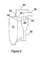
- FIG. 2 is a schematic, side elevational view of the upper portion of a circulating fluidized bed reactor illustrating a preferred embodiment of the present invention.
- FIG. 3 is a schematic, side elevational view of the upper portion of a circulating fluidized bed reactor illustrating another preferred embodiment of the present invention.
- FIG. 4 is a schematic, side elevational view of the upper portion of a circulating fluidized bed reactor illustrating yet another preferred embodiment of the present invention.
- FIG. 1 the overall schematic of a typical circulating fluidized bed reactor system 10 is shown.
- Particulate fuel, inert bed material, and possible auxiliary material, such as limestone are introduced to the furnace 12 of the reactor system 10 by solid material feeders 14, such as screw feeders or pneumatic feeders.
- the solid materials form a bed, which is fluidized by primary gas 16 introduced through a bottom grid 18.
- the velocity of the fluidizing gas in the furnace is typically from about 4 m/s to about 9 m/s.
- the reactions, such as combustion, of the fuel are completed by secondary gas 20 introduced through the sidewalls 22 of the furnace 12.
- the reactions in the furnace 12 produce gases, such as flue gases, which are discharged together with particles entrained with the gases from the furnace 12 through a discharge port 24 to a discharge duct 26, and further to a particle separator 28.
- gases such as flue gases
- the particle separator 28 which is usually a cyclone separator, most (for example 99.9 %) of the particles entrained with the exhaust gases are separated from the exhaust gases.
- the separated particles are conducted along a return duct 30 connected to the bottom of the separator 28 via a loop seal 32 back to the lower portion of the furnace 12.
- Cleaned exhaust gases are discharged from the particle separator 28 through a central gas outlet 34, usually arranged at the top of the separator, to an exhaust gas duct 36.
- the gases are usually conducted through a heat recovery area 38 and a dust separator 40 to a stack 42.
- the exhaust gas duct 36 may comprise further components, such as gas cleaning components, or the like, which are known to those skilled in the art, but such are not shown in Fig. 1 .
- fly ash A portion of the solid particles discharged from the furnace 12 through the discharge port 24 -- so-called fly ash -- is not separated from the exhaust gases in the particle separator 28, but escapes through the gas outlet 34.
- a portion of the fly ash may be collected in a hopper 44 arranged in the exhaust gas duct 36, but most of it is collected by the dust separator 40.
- the portion of the solid material in the furnace 12 that does not escape through the gas outlet 34, is eventually discharged from the furnace as bottom ash 46. While the bottom ash is usually at a temperature of about 650 to about 850 °C, it is cooled by a bottom ash cooler 48 to a lower temperature (e.g., about 300 °C), before it is discharged from the reactor 10.
- Fig. 2 shows a bypass duct 50 coupled between the top of the furnace 12 and the exhaust gas duct 36. Due to the pressure difference between the furnace 12 and the exhaust gas duct 36, a stream of gas and entrained fine solids tends to flow through the duct 50, thus bypassing the particle separator 28.
- the top of the furnace 12 is provided with another outlet opening 52 connected to the first end of the bypass duct 50.
- the first end of the bypass duct 50 may be connected to the same outlet 24 with the discharge duct 26 by , for instance, a branch pipe.
- the first end of the bypass duct 50 may be connected to the discharge duct 26 somewhere between the outlet opening 24 and the inlet into the particle separator 28.
- the purpose of the bypass duct 50 is to receive a portion of the exhaust gases, and some solid particles entrained with the exhaust gases, from the furnace 12 and to take the received portion of the exhaust gas to the exhaust gas duct 36 downstream of the particle separator 28.
- a portion of the solid particles are positively taken out of the fluidized bed circulation, and not returned back to the furnace 12.
- the amount of fly ash, collected in the hopper 44 and the dust separator 40 is increased.
- the amount of bed material circulating in the furnace 12 and the particle separator 28 is decreased.
- the sizing and geometry of the bypass duct 50 determine the quantity of solids taken to the cyclone separator outlet stream.
- the bypass duct 50 is provided with an additional means for controlling flow of the exhaust gas in the bypass duct 50.
- the controlling means comprises gas piping 54 equipped with a control damper 56, such as a butterfly valve.
- the additional gas piping 54 is used for introducing gas, such as air, to the bypass duct 50 so as to decrease the amount of exhaust gases and solid particles flowing through the bypass duct 50 from the furnace 12 to the exhaust gas duct 36.
- the damper 56 By using the damper 56, the amount of introduced gas, and the amount of bypassing gas and particles, can be adjusted.
- the medium through piping 54 can be, for example, air or recirculated flue gas.
- the controlling means comprises a control valve 58 installed directly in the bypass duct 50.
- This embodiment gives the broadest possible flexibility, because, as the exhaust gas flows in, the bypass duct can be adjusted between totally blocked and fully open positions.
- Other suitable controlling means may include a passage and a port allowing exhaust gas and entrained particles to enter the flue gas channel upstream of the particle separator.
- the first end of the bypass duct could also be connected in various different ways upstream of the particle separator 28 in the embodiments of FIGS. 3 and 4 , as was described above with reference to the embodiment shown in FIG. 2 .
- the result in the second and third embodiments compared to the first one, is that the composition of the bed material can be better controlled. That is, the amount and particle size distribution of the bed material can be adjusted to better meet the demands of the fluidized bed process.
- the bypass duct 50 may be manufactured of refractory lined pipes or conduits, or they may be pipes or components lined with an appropriate metal and/or ceramic material. It is self-evident that the lining has to endure both high temperature and high velocity of the solids. Suitable lining materials will be readily apparent to those skilled in the art.
Landscapes
- Engineering & Computer Science (AREA)
- Chemical & Material Sciences (AREA)
- Combustion & Propulsion (AREA)
- Mechanical Engineering (AREA)
- General Engineering & Computer Science (AREA)
- Fluidized-Bed Combustion And Resonant Combustion (AREA)
- Cyclones (AREA)
- Crucibles And Fluidized-Bed Furnaces (AREA)
- Waste-Gas Treatment And Other Accessory Devices For Furnaces (AREA)
- Devices And Processes Conducted In The Presence Of Fluids And Solid Particles (AREA)
Claims (14)
- Verfahren zum Betreiben eines Reaktors mit zirkulierender Wirbelschicht, umfassend eine Feuerung (12) mit einer Ablauföffnung für Abgas (24) und einen Partikelabscheider (28) zur Trennung von Feststoffpartikeln aus Abgas, mit einem Einlass, der über einen Ablaufkanal fürs Abgas (26) mit der Abgas-Ablauföffnung (24) verbunden ist, und einem Gasauslass (34), der mit einem Abgaskanal (36) verbunden ist, und einem Feststoffauslass, der mit einem Rückführkanal (30) zur Rückführung der abgeschiedenen Feststoffpartikel zurück zur Feuerung (12) verbunden ist, welches Verfahren folgende Schritte umfasst:Anordnung eines den Partikelabscheider (28) umgehenden Bypasskanals (50); undLeitung eines Teilstroms von Abgas und mitgeführten Feststoffpartikeln im Bypasskanal (50) vom oberen Teil der Feuerung (12) zum Abgaskanal (36) zur Erhöhung des Feststoffpartikelgehalts im Abgas nach dem Partikelabscheider.
- Verfahren nach Anspruch 1, des Weiteren umfassend den Schritt zur Regelung des Abgasstroms im Bypasskanal (50), um die Menge der den Partikelabscheider umgehenden Feststoffpartikel einzustellen.
- Verfahren nach Anspruch 2, worin der Abgasstrom im Bypasskanal (50) geregelt wird, indem zusätzliches Gas dem Bypasskanal zugeführt wird.
- Verfahren nach Anspruch 2, worin der Abgasstrom im Bypasskanal (50) durch ein Regelventil (58) geregelt wird, das im Bypasskanal angeordnet ist.
- Reaktor mit zirkulierender Wirbelschicht, der Reaktor umfassend:eine Feuerung (12) mit einer Wirbelschicht von Feststoffpartikeln;eine Ablauföffnung (24) zum Entfernen von Abgas samt mitgeführten Feststoffpartikeln aus der Feuerung (12);einen Partikelabscheider (28), der über einen Ablaufkanal (26) mit der Ablauföffnung (24) verbunden ist zur Abscheidung von Feststoffpartikeln aus dem Abgas, welcher Partikelabscheider einen mit einem Abgaskanal (36) verbunden Abgasauslass (34) und einen mit einem Rückführkanal (30) verbundenen Feststoffauslass hat zur Rückführung der abgeschiedenen Feststoffpartikel zurück in den unteren Teil der Feuerung (12);gekennzeichnet durch Mittel (50) zur Leitung eines Teils des Abgases und der mitgeführten Feststoffpartikel vom oberen Teil der Feuerung (12) zum Abgaskanal (36) am Partikelabscheider (28) vorbei, um die Menge von Feststoffpartikeln zu verringern, die in den Partikelabscheider eintreten.
- Apparatur nach Anspruch 5, worin es sich bei den Leitungsmitteln um einen Bypasskanal (50) handelt, dessen erstes Ende stromaufwärts vom Partikelabscheider angeschlossen ist, und ein zweites Ende mit dem Abgaskanal (36) stromabwärts vom Partikelabscheider (28) verbunden ist.
- Apparatur nach Anspruch 6, worin das erste Ende des Bypasskanals (50) mit dem oberen Teil der Feuerung verbunden (12) ist.
- Apparatur nach Anspruch 6, worin das erste Ende des Bypasskanals (50) mit dem Ablaufkanal (26) zwischen dem oberen Teil der Feuerung (12) und dem Partikelabscheider (28) verbunden ist.
- Apparatur nach Anspruch 6, worin der Bypasskanal (50) mit Mitteln (54, 56, 58) zur Regelung der Abgasströmung im Bypasskanal versehen ist.
- Apparatur nach Anspruch 9, worin es sich bei den Regelungsmitteln um zusätzliche Gasrohre (54) handelt, die Gas in den Bypasskanal (50) einführen.
- Apparatur nach Anspruch 10, worin die zusätzlichen Gasrohre (54) mit Mitteln (56) zur Einstellung der Gasmenge versehen sind, die in den Bypasskanal (50) eingeführt wird.
- Apparatur nach Anspruch 9, worin es sich bei den Regelungsmitteln um ein Regelventil (58) handelt, das imstande ist, den Bypasskanal (50) abzusperren.
- Apparatur nach Anspruch 5, worin der Bypasskanal (50) ausgekleidet ist, um der Temperatur und dem im Bypasskanal fließenden Feststoff stand zu halten.
- Apparatur nach Anspruch 5, worin der Partikelabscheider (28) ein Zyklonabscheider ist.
Priority Applications (1)
| Application Number | Priority Date | Filing Date | Title |
|---|---|---|---|
| PL05792262T PL1807657T3 (pl) | 2004-10-13 | 2005-10-10 | Cyklonowy kanał bocznikowy dla reaktora z obiegowym złożem fluidalnym |
Applications Claiming Priority (2)
| Application Number | Priority Date | Filing Date | Title |
|---|---|---|---|
| US10/962,590 US7287477B2 (en) | 2004-10-13 | 2004-10-13 | Cyclone bypass for a circulating fluidized bed reactor |
| PCT/IB2005/002987 WO2006040639A1 (en) | 2004-10-13 | 2005-10-10 | Cyclone bypass for a circulating fluidized bed reactor |
Publications (2)
| Publication Number | Publication Date |
|---|---|
| EP1807657A1 EP1807657A1 (de) | 2007-07-18 |
| EP1807657B1 true EP1807657B1 (de) | 2008-04-30 |
Family
ID=35511304
Family Applications (1)
| Application Number | Title | Priority Date | Filing Date |
|---|---|---|---|
| EP05792262A Expired - Lifetime EP1807657B1 (de) | 2004-10-13 | 2005-10-10 | Zyklonenbypass für umlaufwirbelbettreaktor |
Country Status (11)
| Country | Link |
|---|---|
| US (1) | US7287477B2 (de) |
| EP (1) | EP1807657B1 (de) |
| JP (1) | JP2008516186A (de) |
| KR (1) | KR20070061870A (de) |
| CN (1) | CN101124434B (de) |
| AT (1) | ATE393900T1 (de) |
| DE (1) | DE602005006433T2 (de) |
| ES (1) | ES2306218T3 (de) |
| PL (1) | PL1807657T3 (de) |
| RU (1) | RU2343348C1 (de) |
| WO (1) | WO2006040639A1 (de) |
Families Citing this family (14)
| Publication number | Priority date | Publication date | Assignee | Title |
|---|---|---|---|---|
| CA2496839A1 (en) | 2004-07-19 | 2006-01-19 | Woodland Chemical Systems Inc. | Process for producing ethanol from synthesis gas rich in carbon monoxide |
| US7487456B2 (en) * | 2005-04-06 | 2009-02-03 | Microsoft Corporation | System and method for automatically populating appointment fields |
| ES2539761T3 (es) | 2006-04-05 | 2015-07-03 | Woodland Biofuels Inc. | Sistema y método para convertir biomasa en etanol a través del gas de síntesis |
| CN101353582B (zh) * | 2007-07-25 | 2010-12-01 | 中国科学院工程热物理研究所 | 固体热载体快速热解方法及装置 |
| US8047162B2 (en) * | 2007-07-27 | 2011-11-01 | Babcock & Wilcox Power Generation Group, Inc. | Black plant steam furnace injection |
| JP5417753B2 (ja) * | 2008-07-11 | 2014-02-19 | 株式会社Ihi | 循環流動層ガス化炉 |
| US8196533B2 (en) * | 2008-10-27 | 2012-06-12 | Kentucky-Tennessee Clay Co. | Methods for operating a fluidized-bed reactor |
| FI124762B (fi) * | 2009-04-09 | 2015-01-15 | Foster Wheeler Energia Oy | Kiertoleijupetikattila |
| AT13401U1 (de) * | 2013-04-11 | 2013-12-15 | A Tec Holding Gmbh | Vorrichtung zum Entnehmen von Heißgas |
| CN103438446B (zh) * | 2013-09-02 | 2016-06-08 | 东南大学 | 一种可双向控制返料的密封返料阀 |
| KR101987129B1 (ko) * | 2016-09-19 | 2019-06-10 | 한화케미칼 주식회사 | 3염화 실란 합성용 유동층 반응기 |
| CN109990270A (zh) * | 2019-04-06 | 2019-07-09 | 骆姝颖 | 一种采用煤矸石燃烧的流化床锅炉 |
| CN110260302B (zh) * | 2019-06-26 | 2020-05-22 | 西安交通大学 | 一种流化床气化飞灰的燃用系统 |
| CN116282975B (zh) * | 2023-03-23 | 2025-02-14 | 沈阳鑫博工业技术股份有限公司 | 一种提高轻烧氧化镁浓度的反应器装置及方法 |
Family Cites Families (10)
| Publication number | Priority date | Publication date | Assignee | Title |
|---|---|---|---|---|
| US4419964A (en) * | 1979-10-26 | 1983-12-13 | F. L. Smidth & Co. | Combustion plant |
| DE3406200A1 (de) * | 1984-02-21 | 1985-08-22 | Deutsche Babcock Werke AG, 4200 Oberhausen | Dampferzeuger mit einer stationaeren wirbelschichtfeuerung |
| FR2587090B1 (fr) * | 1985-09-09 | 1987-12-04 | Framatome Sa | Chaudiere a lit fluidise circulant |
| DE3625992A1 (de) * | 1986-07-31 | 1988-02-04 | Steinmueller Gmbh L & C | Verfahren zum verbrennen von kohlenstoffhaltigen materialien in einer zirkulierenden wirbelschicht und wirbelschichtfeuerungsanlage zur durchfuehrung des verfahrens |
| US4733621A (en) * | 1987-05-08 | 1988-03-29 | A. Ahlstrom Corporation | Apparatus and methods for operating a fluidized bed reactor |
| US5281398A (en) * | 1990-10-15 | 1994-01-25 | A. Ahlstrom Corporation | Centrifugal separator |
| DE4102959A1 (de) * | 1991-02-01 | 1992-08-13 | Metallgesellschaft Ag | Verfahren zum verbrennen von kohle in der zirkulierenden wirbelschicht |
| RU2039908C1 (ru) * | 1992-04-03 | 1995-07-20 | Научно-производственное предприятие "ЭНЭКО" | Топка котла с циркулирующим слоем |
| IN187044B (de) * | 1995-01-27 | 2002-01-05 | Du Pont | |
| CA2389660C (en) * | 1999-11-02 | 2007-10-02 | Consolidated Engineering Company, Inc. | Method and apparatus for combustion of residual carbon in fly ash |
-
2004
- 2004-10-13 US US10/962,590 patent/US7287477B2/en not_active Expired - Fee Related
-
2005
- 2005-10-10 WO PCT/IB2005/002987 patent/WO2006040639A1/en not_active Ceased
- 2005-10-10 DE DE602005006433T patent/DE602005006433T2/de not_active Expired - Lifetime
- 2005-10-10 CN CN2005800350343A patent/CN101124434B/zh not_active Expired - Fee Related
- 2005-10-10 KR KR1020077008368A patent/KR20070061870A/ko not_active Ceased
- 2005-10-10 ES ES05792262T patent/ES2306218T3/es not_active Expired - Lifetime
- 2005-10-10 JP JP2007536279A patent/JP2008516186A/ja active Pending
- 2005-10-10 EP EP05792262A patent/EP1807657B1/de not_active Expired - Lifetime
- 2005-10-10 AT AT05792262T patent/ATE393900T1/de active
- 2005-10-10 PL PL05792262T patent/PL1807657T3/pl unknown
- 2005-10-10 RU RU2007117713/06A patent/RU2343348C1/ru not_active IP Right Cessation
Also Published As
| Publication number | Publication date |
|---|---|
| PL1807657T3 (pl) | 2008-10-31 |
| WO2006040639A1 (en) | 2006-04-20 |
| ATE393900T1 (de) | 2008-05-15 |
| EP1807657A1 (de) | 2007-07-18 |
| US7287477B2 (en) | 2007-10-30 |
| RU2343348C1 (ru) | 2009-01-10 |
| CN101124434A (zh) | 2008-02-13 |
| CN101124434B (zh) | 2010-06-09 |
| KR20070061870A (ko) | 2007-06-14 |
| JP2008516186A (ja) | 2008-05-15 |
| ES2306218T3 (es) | 2008-11-01 |
| DE602005006433T2 (de) | 2009-06-04 |
| DE602005006433D1 (de) | 2008-06-12 |
| US20060075946A1 (en) | 2006-04-13 |
Similar Documents
| Publication | Publication Date | Title |
|---|---|---|
| US7287477B2 (en) | Cyclone bypass for a circulating fluidized bed reactor | |
| CA2521651C (en) | A method of and an apparatus for recovering heat in a fluidized bed reactor | |
| US7316564B2 (en) | Method and installation for regulating the quantity of circulating solids in a circulating fluidized bed reactor system | |
| JPH0631345B2 (ja) | 固体炭素質材料をガス化もしくは燃焼させる方法及び装置 | |
| RU2341729C2 (ru) | Способ снижения выделений диоксида серы из бойлера с циркулирующим псевдоожиженным слоем | |
| CN105143414B (zh) | 产生无颗粒的冷却合成气的方法和系统 | |
| US4741290A (en) | Process for the combustion of carbonaceous materials in a circulating fluidized bed, and fluidized bed furnace installation for performing the process | |
| CN1051364C (zh) | 流化床反应器及其操作方法 | |
| US5634516A (en) | Method and apparatus for treating or utilizing a hot gas flow | |
| US4974411A (en) | Supercharged coal-fired steam generator | |
| US5954000A (en) | Fluid bed ash cooler | |
| US5469698A (en) | Pressurized circulating fluidized bed reactor combined cycle power generation system | |
| UA79669C2 (en) | Method and unit for production of low temperature coke | |
| CN208649244U (zh) | 一种循环流化床煤气化系统 | |
| RU2091667C1 (ru) | Способ охлаждения рециркулирующего материала в камере сгорания котла с псевдоожиженным слоем и устройство для его осуществления | |
| FI85417C (fi) | Foerfarande och anordning foer reglering av temperaturen i en reaktor med fluidiserad baedd. | |
| JP2000210595A (ja) | 分級性能可変サイクロン | |
| JP2001041414A (ja) | 循環流動層燃焼装置の炉内温度制御装置及びその運転方法 | |
| EP0243156A1 (de) | Wirbelschicht-Reaktor | |
| JPS6156177B2 (de) | ||
| JP2735643B2 (ja) | 微粉炭燃焼装置 | |
| HU188819B (en) | Device for securing the heat flow and/or material flow between various materials,carrying out chemical and physical processes,first for burning or gasifying solid fuel | |
| JPH04273902A (ja) | 流動床燃焼装置のための炉温度制御方法 | |
| JPH02122826A (ja) | 一体型再循環熱交換器を有する流動床反応装置及びその操作方法 | |
| JPH0351995B2 (de) |
Legal Events
| Date | Code | Title | Description |
|---|---|---|---|
| PUAI | Public reference made under article 153(3) epc to a published international application that has entered the european phase |
Free format text: ORIGINAL CODE: 0009012 |
|
| 17P | Request for examination filed |
Effective date: 20070508 |
|
| AK | Designated contracting states |
Kind code of ref document: A1 Designated state(s): AT BE BG CH CY CZ DE DK EE ES FI FR GB GR HU IE IS IT LI LT LU LV MC NL PL PT RO SE SI SK TR |
|
| GRAP | Despatch of communication of intention to grant a patent |
Free format text: ORIGINAL CODE: EPIDOSNIGR1 |
|
| DAX | Request for extension of the european patent (deleted) | ||
| GRAS | Grant fee paid |
Free format text: ORIGINAL CODE: EPIDOSNIGR3 |
|
| GRAA | (expected) grant |
Free format text: ORIGINAL CODE: 0009210 |
|
| AK | Designated contracting states |
Kind code of ref document: B1 Designated state(s): AT BE BG CH CY CZ DE DK EE ES FI FR GB GR HU IE IS IT LI LT LU LV MC NL PL PT RO SE SI SK TR |
|
| REG | Reference to a national code |
Ref country code: GB Ref legal event code: FG4D |
|
| REG | Reference to a national code |
Ref country code: CH Ref legal event code: EP |
|
| REG | Reference to a national code |
Ref country code: IE Ref legal event code: FG4D Free format text: LANGUAGE OF EP DOCUMENT: FRENCH |
|
| REF | Corresponds to: |
Ref document number: 602005006433 Country of ref document: DE Date of ref document: 20080612 Kind code of ref document: P |
|
| REG | Reference to a national code |
Ref country code: GR Ref legal event code: EP Ref document number: 20080401824 Country of ref document: GR |
|
| PG25 | Lapsed in a contracting state [announced via postgrant information from national office to epo] |
Ref country code: SI Free format text: LAPSE BECAUSE OF FAILURE TO SUBMIT A TRANSLATION OF THE DESCRIPTION OR TO PAY THE FEE WITHIN THE PRESCRIBED TIME-LIMIT Effective date: 20080430 |
|
| NLV1 | Nl: lapsed or annulled due to failure to fulfill the requirements of art. 29p and 29m of the patents act | ||
| PG25 | Lapsed in a contracting state [announced via postgrant information from national office to epo] |
Ref country code: NL Free format text: LAPSE BECAUSE OF FAILURE TO SUBMIT A TRANSLATION OF THE DESCRIPTION OR TO PAY THE FEE WITHIN THE PRESCRIBED TIME-LIMIT Effective date: 20080430 Ref country code: BG Free format text: LAPSE BECAUSE OF FAILURE TO SUBMIT A TRANSLATION OF THE DESCRIPTION OR TO PAY THE FEE WITHIN THE PRESCRIBED TIME-LIMIT Effective date: 20080730 Ref country code: PT Free format text: LAPSE BECAUSE OF FAILURE TO SUBMIT A TRANSLATION OF THE DESCRIPTION OR TO PAY THE FEE WITHIN THE PRESCRIBED TIME-LIMIT Effective date: 20080930 |
|
| REG | Reference to a national code |
Ref country code: PL Ref legal event code: T3 |
|
| REG | Reference to a national code |
Ref country code: ES Ref legal event code: FG2A Ref document number: 2306218 Country of ref document: ES Kind code of ref document: T3 |
|
| PG25 | Lapsed in a contracting state [announced via postgrant information from national office to epo] |
Ref country code: LV Free format text: LAPSE BECAUSE OF FAILURE TO SUBMIT A TRANSLATION OF THE DESCRIPTION OR TO PAY THE FEE WITHIN THE PRESCRIBED TIME-LIMIT Effective date: 20080430 |
|
| PGFP | Annual fee paid to national office [announced via postgrant information from national office to epo] |
Ref country code: FI Payment date: 20080916 Year of fee payment: 4 |
|
| REG | Reference to a national code |
Ref country code: HU Ref legal event code: AG4A Ref document number: E003827 Country of ref document: HU |
|
| PG25 | Lapsed in a contracting state [announced via postgrant information from national office to epo] |
Ref country code: IS Free format text: LAPSE BECAUSE OF FAILURE TO SUBMIT A TRANSLATION OF THE DESCRIPTION OR TO PAY THE FEE WITHIN THE PRESCRIBED TIME-LIMIT Effective date: 20080830 |
|
| ET | Fr: translation filed | ||
| PG25 | Lapsed in a contracting state [announced via postgrant information from national office to epo] |
Ref country code: DK Free format text: LAPSE BECAUSE OF FAILURE TO SUBMIT A TRANSLATION OF THE DESCRIPTION OR TO PAY THE FEE WITHIN THE PRESCRIBED TIME-LIMIT Effective date: 20080430 Ref country code: SE Free format text: LAPSE BECAUSE OF FAILURE TO SUBMIT A TRANSLATION OF THE DESCRIPTION OR TO PAY THE FEE WITHIN THE PRESCRIBED TIME-LIMIT Effective date: 20080731 Ref country code: LT Free format text: LAPSE BECAUSE OF FAILURE TO SUBMIT A TRANSLATION OF THE DESCRIPTION OR TO PAY THE FEE WITHIN THE PRESCRIBED TIME-LIMIT Effective date: 20080430 |
|
| PG25 | Lapsed in a contracting state [announced via postgrant information from national office to epo] |
Ref country code: BE Free format text: LAPSE BECAUSE OF FAILURE TO SUBMIT A TRANSLATION OF THE DESCRIPTION OR TO PAY THE FEE WITHIN THE PRESCRIBED TIME-LIMIT Effective date: 20080430 Ref country code: RO Free format text: LAPSE BECAUSE OF FAILURE TO SUBMIT A TRANSLATION OF THE DESCRIPTION OR TO PAY THE FEE WITHIN THE PRESCRIBED TIME-LIMIT Effective date: 20080430 Ref country code: SK Free format text: LAPSE BECAUSE OF FAILURE TO SUBMIT A TRANSLATION OF THE DESCRIPTION OR TO PAY THE FEE WITHIN THE PRESCRIBED TIME-LIMIT Effective date: 20080430 |
|
| PLBE | No opposition filed within time limit |
Free format text: ORIGINAL CODE: 0009261 |
|
| STAA | Information on the status of an ep patent application or granted ep patent |
Free format text: STATUS: NO OPPOSITION FILED WITHIN TIME LIMIT |
|
| 26N | No opposition filed |
Effective date: 20090202 |
|
| PG25 | Lapsed in a contracting state [announced via postgrant information from national office to epo] |
Ref country code: EE Free format text: LAPSE BECAUSE OF FAILURE TO SUBMIT A TRANSLATION OF THE DESCRIPTION OR TO PAY THE FEE WITHIN THE PRESCRIBED TIME-LIMIT Effective date: 20080430 |
|
| PG25 | Lapsed in a contracting state [announced via postgrant information from national office to epo] |
Ref country code: MC Free format text: LAPSE BECAUSE OF NON-PAYMENT OF DUE FEES Effective date: 20081031 |
|
| REG | Reference to a national code |
Ref country code: IE Ref legal event code: MM4A |
|
| PG25 | Lapsed in a contracting state [announced via postgrant information from national office to epo] |
Ref country code: IT Free format text: LAPSE BECAUSE OF FAILURE TO SUBMIT A TRANSLATION OF THE DESCRIPTION OR TO PAY THE FEE WITHIN THE PRESCRIBED TIME-LIMIT Effective date: 20080430 |
|
| PG25 | Lapsed in a contracting state [announced via postgrant information from national office to epo] |
Ref country code: IE Free format text: LAPSE BECAUSE OF NON-PAYMENT OF DUE FEES Effective date: 20081010 |
|
| PGFP | Annual fee paid to national office [announced via postgrant information from national office to epo] |
Ref country code: HU Payment date: 20080930 Year of fee payment: 4 |
|
| REG | Reference to a national code |
Ref country code: CH Ref legal event code: PL |
|
| PG25 | Lapsed in a contracting state [announced via postgrant information from national office to epo] |
Ref country code: LU Free format text: LAPSE BECAUSE OF NON-PAYMENT OF DUE FEES Effective date: 20081010 Ref country code: CY Free format text: LAPSE BECAUSE OF FAILURE TO SUBMIT A TRANSLATION OF THE DESCRIPTION OR TO PAY THE FEE WITHIN THE PRESCRIBED TIME-LIMIT Effective date: 20080430 Ref country code: HU Free format text: LAPSE BECAUSE OF NON-PAYMENT OF DUE FEES Effective date: 20091011 |
|
| PG25 | Lapsed in a contracting state [announced via postgrant information from national office to epo] |
Ref country code: FI Free format text: LAPSE BECAUSE OF NON-PAYMENT OF DUE FEES Effective date: 20091010 Ref country code: TR Free format text: LAPSE BECAUSE OF FAILURE TO SUBMIT A TRANSLATION OF THE DESCRIPTION OR TO PAY THE FEE WITHIN THE PRESCRIBED TIME-LIMIT Effective date: 20080430 |
|
| PG25 | Lapsed in a contracting state [announced via postgrant information from national office to epo] |
Ref country code: CH Free format text: LAPSE BECAUSE OF NON-PAYMENT OF DUE FEES Effective date: 20091031 Ref country code: LI Free format text: LAPSE BECAUSE OF NON-PAYMENT OF DUE FEES Effective date: 20091031 |
|
| PGFP | Annual fee paid to national office [announced via postgrant information from national office to epo] |
Ref country code: CZ Payment date: 20111005 Year of fee payment: 7 |
|
| PGFP | Annual fee paid to national office [announced via postgrant information from national office to epo] |
Ref country code: PL Payment date: 20120925 Year of fee payment: 8 |
|
| PGFP | Annual fee paid to national office [announced via postgrant information from national office to epo] |
Ref country code: DE Payment date: 20121023 Year of fee payment: 8 Ref country code: FR Payment date: 20121031 Year of fee payment: 8 |
|
| PGFP | Annual fee paid to national office [announced via postgrant information from national office to epo] |
Ref country code: GR Payment date: 20121030 Year of fee payment: 8 Ref country code: GB Payment date: 20121019 Year of fee payment: 8 Ref country code: ES Payment date: 20121019 Year of fee payment: 8 |
|
| PGFP | Annual fee paid to national office [announced via postgrant information from national office to epo] |
Ref country code: AT Payment date: 20121011 Year of fee payment: 8 |
|
| REG | Reference to a national code |
Ref country code: AT Ref legal event code: MM01 Ref document number: 393900 Country of ref document: AT Kind code of ref document: T Effective date: 20131010 |
|
| GBPC | Gb: european patent ceased through non-payment of renewal fee |
Effective date: 20131010 |
|
| REG | Reference to a national code |
Ref country code: GR Ref legal event code: ML Ref document number: 20080401824 Country of ref document: GR Effective date: 20140505 |
|
| PG25 | Lapsed in a contracting state [announced via postgrant information from national office to epo] |
Ref country code: GB Free format text: LAPSE BECAUSE OF NON-PAYMENT OF DUE FEES Effective date: 20131010 |
|
| REG | Reference to a national code |
Ref country code: DE Ref legal event code: R119 Ref document number: 602005006433 Country of ref document: DE Effective date: 20140501 |
|
| REG | Reference to a national code |
Ref country code: FR Ref legal event code: ST Effective date: 20140630 |
|
| PG25 | Lapsed in a contracting state [announced via postgrant information from national office to epo] |
Ref country code: AT Free format text: LAPSE BECAUSE OF NON-PAYMENT OF DUE FEES Effective date: 20131010 Ref country code: DE Free format text: LAPSE BECAUSE OF NON-PAYMENT OF DUE FEES Effective date: 20140501 Ref country code: FR Free format text: LAPSE BECAUSE OF NON-PAYMENT OF DUE FEES Effective date: 20131031 Ref country code: GR Free format text: LAPSE BECAUSE OF NON-PAYMENT OF DUE FEES Effective date: 20140505 Ref country code: CZ Free format text: LAPSE BECAUSE OF NON-PAYMENT OF DUE FEES Effective date: 20131010 |
|
| REG | Reference to a national code |
Ref country code: PL Ref legal event code: LAPE |
|
| PG25 | Lapsed in a contracting state [announced via postgrant information from national office to epo] |
Ref country code: PL Free format text: LAPSE BECAUSE OF NON-PAYMENT OF DUE FEES Effective date: 20131010 |
|
| REG | Reference to a national code |
Ref country code: ES Ref legal event code: FD2A Effective date: 20150709 |
|
| PG25 | Lapsed in a contracting state [announced via postgrant information from national office to epo] |
Ref country code: ES Free format text: LAPSE BECAUSE OF NON-PAYMENT OF DUE FEES Effective date: 20131011 |