EP1808150B1 - Injecteur pour lentille intraoculaire et système d'injection utilisant celui-ci - Google Patents
Injecteur pour lentille intraoculaire et système d'injection utilisant celui-ci Download PDFInfo
- Publication number
- EP1808150B1 EP1808150B1 EP07000508.7A EP07000508A EP1808150B1 EP 1808150 B1 EP1808150 B1 EP 1808150B1 EP 07000508 A EP07000508 A EP 07000508A EP 1808150 B1 EP1808150 B1 EP 1808150B1
- Authority
- EP
- European Patent Office
- Prior art keywords
- lens
- intraocular lens
- injecting
- injector
- cartridge
- Prior art date
- Legal status (The legal status is an assumption and is not a legal conclusion. Google has not performed a legal analysis and makes no representation as to the accuracy of the status listed.)
- Not-in-force
Links
- 239000000314 lubricant Substances 0.000 claims description 30
- 210000000695 crystalline len Anatomy 0.000 description 114
- 230000003287 optical effect Effects 0.000 description 18
- 238000002347 injection Methods 0.000 description 4
- 239000007924 injection Substances 0.000 description 4
- 229920002818 (Hydroxyethyl)methacrylate Polymers 0.000 description 2
- 210000003811 finger Anatomy 0.000 description 2
- 239000000463 material Substances 0.000 description 2
- 229920003229 poly(methyl methacrylate) Polymers 0.000 description 2
- 239000004926 polymethyl methacrylate Substances 0.000 description 2
- 208000002177 Cataract Diseases 0.000 description 1
- WOBHKFSMXKNTIM-UHFFFAOYSA-N Hydroxyethyl methacrylate Chemical compound CC(=C)C(=O)OCCO WOBHKFSMXKNTIM-UHFFFAOYSA-N 0.000 description 1
- CERQOIWHTDAKMF-UHFFFAOYSA-M Methacrylate Chemical compound CC(=C)C([O-])=O CERQOIWHTDAKMF-UHFFFAOYSA-M 0.000 description 1
- KEAYESYHFKHZAL-UHFFFAOYSA-N Sodium Chemical compound [Na] KEAYESYHFKHZAL-UHFFFAOYSA-N 0.000 description 1
- 125000005396 acrylic acid ester group Chemical group 0.000 description 1
- 239000002131 composite material Substances 0.000 description 1
- 230000001681 protective effect Effects 0.000 description 1
- 210000003813 thumb Anatomy 0.000 description 1
- 229940006076 viscoelastic substance Drugs 0.000 description 1
- 239000003190 viscoelastic substance Substances 0.000 description 1
Images




Classifications
-
- A—HUMAN NECESSITIES
- A61—MEDICAL OR VETERINARY SCIENCE; HYGIENE
- A61F—FILTERS IMPLANTABLE INTO BLOOD VESSELS; PROSTHESES; DEVICES PROVIDING PATENCY TO, OR PREVENTING COLLAPSING OF, TUBULAR STRUCTURES OF THE BODY, e.g. STENTS; ORTHOPAEDIC, NURSING OR CONTRACEPTIVE DEVICES; FOMENTATION; TREATMENT OR PROTECTION OF EYES OR EARS; BANDAGES, DRESSINGS OR ABSORBENT PADS; FIRST-AID KITS
- A61F2/00—Filters implantable into blood vessels; Prostheses, i.e. artificial substitutes or replacements for parts of the body; Appliances for connecting them with the body; Devices providing patency to, or preventing collapsing of, tubular structures of the body, e.g. stents
- A61F2/02—Prostheses implantable into the body
- A61F2/14—Eye parts, e.g. lenses or corneal implants; Artificial eyes
- A61F2/16—Intraocular lenses
- A61F2/1662—Instruments for inserting intraocular lenses into the eye
- A61F2/1675—Instruments for inserting intraocular lenses into the eye with a lubricated inner surface, e.g. the lubricant being coated on the inner surface or being injected through a port
-
- A—HUMAN NECESSITIES
- A61—MEDICAL OR VETERINARY SCIENCE; HYGIENE
- A61F—FILTERS IMPLANTABLE INTO BLOOD VESSELS; PROSTHESES; DEVICES PROVIDING PATENCY TO, OR PREVENTING COLLAPSING OF, TUBULAR STRUCTURES OF THE BODY, e.g. STENTS; ORTHOPAEDIC, NURSING OR CONTRACEPTIVE DEVICES; FOMENTATION; TREATMENT OR PROTECTION OF EYES OR EARS; BANDAGES, DRESSINGS OR ABSORBENT PADS; FIRST-AID KITS
- A61F2/00—Filters implantable into blood vessels; Prostheses, i.e. artificial substitutes or replacements for parts of the body; Appliances for connecting them with the body; Devices providing patency to, or preventing collapsing of, tubular structures of the body, e.g. stents
- A61F2/02—Prostheses implantable into the body
- A61F2/14—Eye parts, e.g. lenses or corneal implants; Artificial eyes
- A61F2/16—Intraocular lenses
- A61F2/1662—Instruments for inserting intraocular lenses into the eye
- A61F2/1678—Instruments for inserting intraocular lenses into the eye with a separate cartridge or other lens setting part for storage of a lens, e.g. preloadable for shipping
-
- A—HUMAN NECESSITIES
- A61—MEDICAL OR VETERINARY SCIENCE; HYGIENE
- A61F—FILTERS IMPLANTABLE INTO BLOOD VESSELS; PROSTHESES; DEVICES PROVIDING PATENCY TO, OR PREVENTING COLLAPSING OF, TUBULAR STRUCTURES OF THE BODY, e.g. STENTS; ORTHOPAEDIC, NURSING OR CONTRACEPTIVE DEVICES; FOMENTATION; TREATMENT OR PROTECTION OF EYES OR EARS; BANDAGES, DRESSINGS OR ABSORBENT PADS; FIRST-AID KITS
- A61F2/00—Filters implantable into blood vessels; Prostheses, i.e. artificial substitutes or replacements for parts of the body; Appliances for connecting them with the body; Devices providing patency to, or preventing collapsing of, tubular structures of the body, e.g. stents
- A61F2/02—Prostheses implantable into the body
- A61F2/14—Eye parts, e.g. lenses or corneal implants; Artificial eyes
- A61F2/16—Intraocular lenses
- A61F2/1691—Packages or dispensers for intraocular lenses
Definitions
- the present invention relates to an intraocular lens injector that injects an intraocular lens into an eye, and an intraocular lens injecting system including the intraocular lens injector.
- an intraocular lens injector which injects an intraocular lens into an eye with a clouded crystalline lens extracted, is generally used.
- Lubricant viscoelastic substance
- Lubricant is injected into such the injector to move smoothly the intraocular lens in the injector.
- the lubricant is injected into the injector.
- the document W003045285 discloses an intraocular lens injector according to the preamble of claim 1, having a loading channel fillable at least partially, but preferably completely, with a viscous lubricant.
- the present invention is characterized by the features of claim 1.
- FIG. 1 is a schematic view showing an intraocular lens injecting system according to an embodiment of the invention.
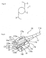
- Fig. 2 is a schematic view showing an intraocular lens.
- An intraocular lens injecting system 100 includes an intraocular lens injector 50 that injects a foldable intraocular lens 1 into an eye, and a holder (a casing) 30 that fixedly holds the injector 50.
- the injector 50 includes a lens cartridge (a lens holding unit) 10 that holds the intraocular lens 1, and a handpiece (a cartridge holding unit) 20 as an injector body that holds the cartridge 10.
- the intraocular lens 1 includes an optical portion 2 having predetermined refractive power and a supporting portion 3 that supports the optical portion 2 in an eye.
- the optical portion 2 is formed of an existing material that is used for a foldable optical portion of an intraocular lens, such as, HEMA (Hydroxyethylmethacrylate), a composite of acrylic acid ester and methacrylate, etc.
- the supporting portion 3 is formed of an existing material that is used for a supporting portion of an intraocular lens, such as PMMA (Polymethylmethacrylate) etc.
- the shape of the intraocular lens 1 is not limited to those in the embodiments of the invention and any shape may be applied as long as it is foldable.
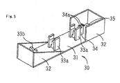
- Fig. 3 is a schematic view of the cartridge 10. Incidentally, upside and downside in the description for Fig. 3 correspond to upside and downside in a normal usage state of the injector 50 (the cartridge 10).
- the cartridge 10 includes an inserting portion 11 that is to be inserted through an incision on an eye and a lens place portion 12 where the intraocular lens 1 is to be placed (held).
- the inserting portion 11 is a tube-shaped part tapered at the front end, in which the intraocular lens 1 folded at the lens place portion 12 passes through a hollow portion and is folded smaller, and then extruded out (discharged outside) through an exit (an outlet) 11a.
- the lens place portion 12 includes a fixed part 12a that is fixed to the inserting portion 11 and a movable part (an opening/closing part) 12b that is coupled to the fixed part 12a through a hinge 13.
- the fixed part 12a includes a placing surface 14a inside and the movable part 12b includes a placing surface 14b inside.
- the intraocular lens 1 is placed on the placing surfaces 14a and 14b in a state that the lens place portion 12 (the fixed part 12a and the movable part 12b) is opened.
- the intraocular lens 1 placed in the state that the lens place portion 12 is opened is not folded (but, movement in the opening/closing direction of the lens place portion 12 is restricted).
- the placing surfaces 14a and 14b form the same shape (half circle) as an inlet 11b of the inserting portion 11 and the intraocular lens 1 placed on the placing surfaces 14a and 14b is folded in the same shape.
- the placing surfaces 14a and 14b are curved such that the intraocular lens 1 is not folded when the lens place portion 12 is opened, and it is folded when the lens place portion 12 is closed.
- a space 19 is defined by a sidewall 120a of the fixed part 12a facing the movable part 12b and a sidewall 120b of the movable part 12b facing the fixed part 12a.
- the fixed part 12a is provided with a cover 15a and the movable part 12b is provided with a cover 15b.
- the covers 15a and 15b cover the upside of the placing surfaces 14a and 14b when the lens place portion 12 is closed.
- a convex portion 16 extending down toward the placing surfaces 14a and 14b is formed at the side of the cover 15b facing the cover 15a .
- the convex portion 16 prevents the intraocular lens 1 from being folded in directions, not the appropriate folding direction of the intraocular lens 1, i.e. not the opening/closing direction of the lens place portion 12.
- a joint portion 17a extending upward is provided at the side of the cover 15a facing the cover 15b and a joint portion 17b extending upward is provided at the side of the cover 15b facing the cover 15a.
- the joint portion 17a is provided with a female hook 170a that is engaged (snap-fitted) with a male hook 170b provided to the joint portion 17b.
- the lens place portion 12 the fixed part 12a and the movable part 12b
- the joint portion 17a is jointed with the joint portion 17b and the female hook 170a is engaged with the male hook 170b.
- a convex fitting portion 18 is provided at an outside of the fixed part 12a (described hereinafter).
- Figs. 4A and 4B are schematic views of the handpiece 20.
- Fig. 4A is a perspective view and Fig. 4B is a cross-sectional view.
- the handpiece 20 includes a cylinder (a body unit) 25 where the cartridge 10 is mounted and a piston (a lens extruding unit) 26 that is inserted in the cylinder 25.
- a mounting portion 20a for the cartridge 10 is formed at the front end of the cylinder 25.
- a flare-shaped finger portion 24 where a user (an operator) puts his/her fingers to hold the handpiece 20 (the cylinder 25) such as a syringe is formed on the outer periphery of the cylinder 25.
- a pushing portion 26a for the thumb to push the piston 26 into the cylinder 25 is provided at the back end of the piston 26.
- the mounting portion 20a includes a first receiving portion 21 for the lens place portion 12 (the fixed part 12a) of the cartridge 10 to be placed (fitted) and a second receiving portion 22 for the inserting portion 11 of the cartridge 10 to be placed (fitted).
- the first receiving portion 21 is shaped like a quadrant circle at the end of the cylinder 25 and the second receiving portion 22 has a letter-C shape in which an arc thereof is a little longer than a half of the circumference around the center axis of the cylinder 25.
- a recess 21a is formed on the first receiving portion 21 by two convex portions 23a and 23b and the fitting portion 18 (see Fig. 3 ) of the cartridge 10 is fitted in the recess 21a. Further, the inserting portion 11 is fitted in a recess 22a of the second receiving portion 22. As combined as described above, the cartridge 10 is fixedly held at the mounting portion 20a in the state that the lens place portion 12 (the fixed part 12a and the movable part 12b) is opened.
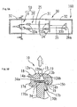
- Fig. 5 is a schematic view of the holder 30.
- a base 31 is provided with a protective wall 32 (a fence) along its edge and includes holding portions 33a and 33b for holding the injector 50.
- Two holding portions 33a are provided so as to chuck the cylinder 25 and the holding portion 33b supports the piston 26 from underneath.
- a circular arc spot facing for the cylinder 25 fitted is formed at the upside of the holding portion 33a and another circular arc spot facing for the piston 26 fitted is formed at the upside of the holding portion 33b.
- the base 31 is provided with a restrictor 34 that restricts movement of the intraocular lens 1 in a forward/backward direction of the injector 50 (a perpendicular direction to the opening/closing direction of the lens place portion 12) in the lens place portion 12 of the cartridge 10.
- the restrictor 34 extends in the direction that the injector 50 is detached from the holder 30.
- a cavity 35 where the intraocular lens 1 (the optical portion 2) is placed is formed on upside of the restrictor 34.
- the front and back sidewalls 34a of the cavity 35 are curved to fit with the circular optical portion 2 and chuck the optical portion 2 from front and rear when the optical portion 2 is placed in the cavity 35.
- the bottom of the cavity 35 is more curved than the optical portion 2, so that when the optical portion 2 is placed in the cavity 35, the periphery of the optical portion 2 contacts with the edge inside the cavity 35. Accordingly, the intraocular lens 1 is stably placed (held). Meanwhile, the width of the restrictor 34 in a left/right direction (the opening/closing direction of the lens place portion 12) is smaller than the diameter of the optical portion 2, so that a part of the edge of the optical portion 2 protrudes to the left and right of the cavity 35.
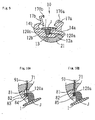
- Figs. 6A and 6B are views showing a state in which the injector 50 is held by the holder 30 (i.e. an intraocular lens injecting system 100).
- Fig. 6A is a plan view taken from above and Fig. 6B is a cross-sectional view taken along a line A-A of Fig. 6A .
- the lens place portion 12 of the cartridge 10 is opened and the intraocular lens 1 placed in the cavity 35 of the restrictor 34 is covered by the cartridge 10.
- movement of the piston 26 in the axial direction thereof (the forward/backward direction) is restricted by the holding portion 33b.
- FIG. 6B is a view showing an arrangement state of the intraocular lens 1 within the injector 50 (the cartridge 10) held by the holder 30.
- the intraocular lens 1 (the optical portion 2) is placed on the restrictor 34 and covered by the cartridge 10 such that it does not contact with the placing surfaces 14a and 14b in the lens place portion 12.
- the width in the left/right direction of the restrictor 34 is smaller than the diameter of the optical portion 2 and a part of the edge of the optical portion 2 protrudes to the left and right of the restrictor 34, when the injector 50 (the cartridge 10) is detached from the holder 30 (the holding portions 33a and 33b) in the direction of an arrow E, the intraocular lens 1 is caught by the placing surfaces 14a and 14b of the cartridge 10 and remains in the lens place portion 12.
- FIG. 7 is a perspective view of a syringe 90 to inject lubricant of hialuronan natrium etc. into the cartridge 10.
- the syringe 90 includes an injecting needle 91 with the front end curved, a cylinder 92 to receive lubricant J, and a piston 93.
- FIGS. 8A , 8B, and 8C are views illustrating a configuration for injecting the lubricant J into the cartridge 10.
- FIG. 8A is a view of the injector 50 supported by the holder 30 seen from the above
- FIG. 8B is a cross-sectional view of FIG. 8A taken along a line B-B
- FIG. 8C is a cross-sectional view of FIG. 8A taken along a line C-C.
- An injecting passage (an injection hole) 80 for injecting the lubricant J into the lens place portion 12 is formed in the cartridge 10.
- the injecting passage 80 is formed through the outerwall of the fixed part 12a to the sidewall 120a of the fixed part 12a. That is, the injecting passage 80 has an inlet 81 at the outerwall of the fixed part 12a and an outlet 82 at the sidewall 120a of the fixed part 12a.
- the outlet 82 is formed at the sidewall 120a such that it is positioned at the vicinity of the center of the optical portion 2 of the intraocular lens 1 placed in the state that the lens place portion 12 open (see FIG. 8B ).
- an injecting passage (an injection hole) 70 for injection the lubricant J into the cartridge 10 (the lens place portion 12) is formed in the first receiving portion 21 of the handpiece 20.
- the injecting passage 70 is formed through the outerwall to the innerwall at substantially center of the first receiving portion 21-That is, the injecting passage 70 has an inlet 71 at the outerwall of the first receiving portion 21 and an outlet 72 at the innerwall of the first receiving portion 21.
- the inlet 71 is longer than the outlet 72 in the forward/backward direction (see FIG- 8) and the injecting passage 70 is tapered forward (see FIG. 8B ).
- the outlet 72 of the injecting passage 70 is communicated with the inlet 81 of the injecting passage 80.
- the injecting needle 91 of the syringe 90 is inserted into the inlet 71, the injecting needle 91 is inserted into the inlet 81 through the outlet 72 and contacts with an innerwall 83 of the injecting passage 80. Accordingly, when the lubricant J is injected into the cartridge 10 (the lens place portion 12) by the syringe 90, the movement of the injecting needle 91 is restricted, so that damage in the intraocular lens 1 due to the contact of the front end of the injecting needle 91 is prevented.
- the innerwall 83 is inclined at a predetermined angle to the insert direction of the injecting needle 91 (see FIG. 8C ), so that it prevents the injecting needle 91 from protruding inside the space 19 through the outlet 82. Accordingly, the front end of the injecting needle 91 does not contact with the intraocular lens 1.
- the configuration for restricting the movement of the injecting needle 91 is not limited to that shown in FIG. 8C , and may be modified in a variety of ways.
- a convex portion 84 may be formed at the outlet 82 in the innerwall 83.
- a concave portion 85 may be formed on the innerwall 83.
- a configuration for restricting the movement of the injecting needle 91 may be formed in the syringe 90.
- a block may be provided at a predetermined position of the injecting needle 91, and the movement of the injecting needle 91 is restricted by contacting the block with the first receiving portion 21.
- a user takes out the injecting system 100 from a case (not shown) for maintaining an aseptic condition and detaches the injector 50 (the cartridge 10) from the holder 30.
- the cartridge 10 is moved in the direction of the arrow E (above the holder 30).
- the intraocular lens 1 placed on the restrictor 34 is not restricted in movement in the detaching direction, so that it can be lifted in contact with the placing surfaces 14a and 14b and is detached from the restrictor 34 (the cavity 35) (that is, released from the restriction by the restrictor 34), and in turn remains in the cartridge 10.
- the intraocular lens 1 is placed (held) in advance in the lens place portion 12.
- the injection of the lubricant J into the cartridge 10 (the lens place portion 12) will be now described.
- the injecting needle 91 of the syringe 90 receiving the lubricant J is first inserted through the inlet 71 until the needle 91 contacts with the innerwall 83. Subsequently, the lubricant J is discharged through the front end of the injecting needle 91 by pushing the piston 93. The discharged lubricant J flows out through the outlet 82 and collects on the intraocular lens 1 (see FIG. 8C ).
- the lubricant J is injected into the cartridge 10 (the lens place portion 12) in a predetermined amount, and the injector 50 (the cartridge 10) rotates to direct the hinge 13 down. Accordingly, the lubricant J collects in the space 19 (see FIG. 9 ). As the lens place portion 12 (the fixed part 12a and the movable part 12b) is closed and the space correspondingly narrows, the lubricant J collecting in the space 19 gradually flows into a space between the placing surfaces 14a and 14b and the intraocular lens 1. When the lens place portion 12 (the fixed part 12a and the movable part 12b) is completely closed, the space 19 does not exist any more and the lubricant J remains between the placing surfaces 14a and 14b and the intraocular lens 1. Accordingly, the lubricant J is inserted into the cartridge 10 (the lens place portion 12) in the state that the intraocular lens 1 is placed (held) inside in advance.
- the intraocular lens 1 With the lens placing portions 12 (the fixed part 12a and the movable part 12b) closed, the intraocular lens 1 is bent by the placing surfaces 14a and 14b that pushing the intraocular lens 1.
- the piston 26 moves inside the cylinder 25 to the front end and pushes the intraocular lens 1 from the lens placing portion 12 into the inserting portion 11.
- the intraocular lens 1 As pushed into the inserting portion 11, the intraocular lens 1 is bent small (rounded). Accordingly, the intraocular lens 1 bent small is discharged through the outlet 11a at the front end of the inserting portion 11.
- an injector having a lens cartridge integrally formed with a handpiece and held by a holder is provided, it is not limited thereto. In other words, only a lens cartridge may be held by a holder. Further, if the lens cartridge is not covered by the hand piece (the first receiving portion 21 in the present embodiment), it is not needed to form the injecting passage (the injecting passage 70 in the present embodiment) in the handpiece. Further, according to the invention, since the injector is held by the holder, the intraocular lens is placed (held) on a part of the holder (the restrictor 34 in the present invention), but, not limited thereto, may be placed (held) in the lens cartridge (e.g. the lens place portion 12).
Landscapes
- Health & Medical Sciences (AREA)
- Ophthalmology & Optometry (AREA)
- Cardiology (AREA)
- Oral & Maxillofacial Surgery (AREA)
- Transplantation (AREA)
- Engineering & Computer Science (AREA)
- Biomedical Technology (AREA)
- Heart & Thoracic Surgery (AREA)
- Vascular Medicine (AREA)
- Life Sciences & Earth Sciences (AREA)
- Animal Behavior & Ethology (AREA)
- General Health & Medical Sciences (AREA)
- Public Health (AREA)
- Veterinary Medicine (AREA)
- Prostheses (AREA)
Claims (6)
- Injecteur pour lentille intraoculaire (50) pour injecter une lentille intraoculaire pliable (1) dans un oeil, l'injecteur comprenant :une cartouche de lentille (10) comprenantune partie d'insertion (11) qui comprend une sortie (11a) pour la lentille intraoculaire insérable par une incision pratiquée sur l'oeil pour injecter la lentille dans l'oeil : etune partie de placement de la lentille (12) où la lentille intraoculaire est placée et qui est formée sur un côté opposé à la sortie de la partie d'insertion, la partie de placement de la lentille pouvant être fermée par une charnière (13) dans une direction dans laquelle la lentille intraoculaire est repliée et la lentille intraoculaire placée est pliée en fermant la partie de placement de la lentille : etune pièce à main (20) sur laquelle la cartouche de lentille est montée,caractérisé en ce queun premier passage d'injection (80) est formé dans la partie de placement de lentille pour injecter un lubrifiant (J) dans la partie de placement de lentille de l'extérieur, etla pièce à main comprend un deuxième passage d'injection (70) pour injecter un lubrifiant dans la partie de placement de lentille de l'extérieur, le deuxième passage d'injection communiquant avec le premier passage d'injection lorsque la cartouche de lentille est montée sur la pièce à main.
- Injecteur de lentille intraoculaire selon la revendication 1, dans lequel la partie de placement de lentille comprend une partie fixe (12a) fixée à la partie d'insertion et une partie mobile (12b) reliée à la partie fixe par la charnière, et
le lubrifiant (J) est injecté dans un espace entre les parties fixe et mobile de telle sorte que les parties fixe et mobile soient ouvertes. - Injecteur de lentille intraoculaire selon la revendication 2, dans lequel le premier passage d'injection est formé dans la partie fixe de sorte qu'une entrée (81) soit formée sur une paroi extérieure de la partie fixe et qu'une sortie (82) soit formée sur une paroi latérale de la partie fixe faisant face à la partie mobile.
- Injecteur de lentille intraoculaire selon l'une quelconque des revendications 1 à 3, dans lequel le premier passage d'injection comprend une partie de restriction (83, 84 et 85) pour restreindre le mouvement d'une aiguille d'injection (91) d'une seringue (90) destinée à injecter le lubrifiant.
- Système d'injection de lentille intraoculaire, comprenant un support (30) qui soutient un injecteur de lentille intraoculaire selon l'une quelconque des revendications 1 à 4.
- Système d'injection de lentille intraoculaire selon la revendication 5, dans lequel
le support comprend un élément de support (34, 34a et 35) qui soutient la lentille intraoculaire dans la partie de placement de lentille ouverte et le lubrifiant est injecté dans la partie de placement de lentille ouverte.
Applications Claiming Priority (1)
| Application Number | Priority Date | Filing Date | Title |
|---|---|---|---|
| JP2006004216A JP4699216B2 (ja) | 2006-01-11 | 2006-01-11 | 眼内レンズ挿入システム |
Publications (2)
| Publication Number | Publication Date |
|---|---|
| EP1808150A1 EP1808150A1 (fr) | 2007-07-18 |
| EP1808150B1 true EP1808150B1 (fr) | 2013-05-15 |
Family
ID=38016435
Family Applications (1)
| Application Number | Title | Priority Date | Filing Date |
|---|---|---|---|
| EP07000508.7A Not-in-force EP1808150B1 (fr) | 2006-01-11 | 2007-01-11 | Injecteur pour lentille intraoculaire et système d'injection utilisant celui-ci |
Country Status (3)
| Country | Link |
|---|---|
| US (1) | US20070168026A1 (fr) |
| EP (1) | EP1808150B1 (fr) |
| JP (1) | JP4699216B2 (fr) |
Families Citing this family (23)
| Publication number | Priority date | Publication date | Assignee | Title |
|---|---|---|---|---|
| US20070150054A1 (en) * | 2005-12-22 | 2007-06-28 | Joel Pynson | Apparatus and methods for loading of an IOL injector |
| US8475526B2 (en) * | 2005-12-22 | 2013-07-02 | Bausch & Lomb Incorporated | Apparatus and methods for loading of an IOL injector |
| EP2111821A4 (fr) * | 2007-02-08 | 2013-10-23 | Kaneka Corp | Injecteur pour les yeux |
| WO2008149795A1 (fr) | 2007-05-30 | 2008-12-11 | Hoya Corporation | Outil utilisé pour l'insertion d'une lentille intraoculaire |
| JP5254669B2 (ja) | 2008-06-05 | 2013-08-07 | Hoya株式会社 | 眼内レンズ挿入器具及びカートリッジ |
| US8658948B2 (en) * | 2009-12-17 | 2014-02-25 | Alcon Research, Ltd. | Docking station with temperature control and electronic identification system |
| JPWO2014208507A1 (ja) * | 2013-06-24 | 2017-02-23 | 興和株式会社 | 眼内レンズの挿入器具 |
| EP3072476B1 (fr) * | 2013-11-19 | 2019-03-27 | Kowa Company, Ltd. | Instrument d'insertion de lentille intraoculaire |
| DE102014005719A1 (de) * | 2014-04-22 | 2015-10-22 | Iolution Gmbh | Behältersystem zum Aufbewahren einer lntraokularlinse |
| JP6540000B2 (ja) * | 2014-12-02 | 2019-07-10 | 株式会社ニデック | 眼内レンズ挿入器具 |
| TR201511576A2 (tr) * | 2015-09-16 | 2017-04-21 | Vsy Biyoteknoloji Ve Ilac Sanayi Anonim Sirketi | Göz i̇çi̇ lensi̇n depolanmasi ve enjeksi̇yonu i̇çi̇n yardimci si̇stem |
| US10993799B2 (en) | 2015-10-16 | 2021-05-04 | Kowa Company, Ltd. | Intraocular lens insertion system, intraocular lens insertion apparatus, and tube |
| DE102015224141B3 (de) | 2015-12-03 | 2017-03-16 | Carl Zeiss Meditec Ag | Intraokularlinsen-Kassette mit Gleitmittel-Zuführkanal und Injektor mit Kassette |
| DE102015224142B3 (de) | 2015-12-03 | 2017-03-23 | Carl Zeiss Meditec Ag | Intraokularlinsen-Kassette mit Deckel und Injektor mit Kassette |
| WO2018003853A1 (fr) | 2016-06-28 | 2018-01-04 | Hoya株式会社 | Instrument d'insertion de lentille intraoculaire |
| US11033382B2 (en) | 2016-06-28 | 2021-06-15 | Hoya Corporation | Intraocular lens injector |
| US20180200105A1 (en) * | 2017-01-14 | 2018-07-19 | Rxsight, Inc. | Intraocular lens inserter cartridge with a trailing haptic protection structure |
| US10722346B2 (en) | 2017-09-19 | 2020-07-28 | Bausch & Lomb Incorporated | Intraocular lens injector assembly having shuttle assembly retaining intraocular lens in storage vial and operably presenting intraocular lens in injector assembly |
| WO2019130028A1 (fr) * | 2017-12-28 | 2019-07-04 | Medicontur Medical Engineering Ltd. | Système d'injecteur pour lentilles intraoculaires |
| JP7162443B2 (ja) | 2018-05-16 | 2022-10-28 | Hoya株式会社 | 容器付き眼内リング挿入器 |
| JP7162445B2 (ja) | 2018-05-25 | 2022-10-28 | Hoya株式会社 | 眼内レンズ挿入器 |
| JP7327956B2 (ja) | 2019-03-13 | 2023-08-16 | Hoya株式会社 | 眼内レンズ挿入器具 |
| CN119499007A (zh) * | 2024-11-25 | 2025-02-25 | 震旭(南通)医疗器械有限公司 | 一种人工晶状体推注器用侧推组件 |
Family Cites Families (11)
| Publication number | Priority date | Publication date | Assignee | Title |
|---|---|---|---|---|
| US4681102A (en) * | 1985-09-11 | 1987-07-21 | Bartell Michael T | Apparatus and method for insertion of an intra-ocular lens |
| JPH0732791B2 (ja) * | 1991-06-13 | 1995-04-12 | キヤノンスター株式会社 | 眼内レンズの移植器具 |
| US5944725A (en) * | 1996-09-26 | 1999-08-31 | Bausch & Lomb Surgical, Inc. | Method and apparatus for inserting a flexible membrane into an eye |
| US5947975A (en) * | 1997-03-07 | 1999-09-07 | Canon Staar Co., Inc. | Inserting device for deformable intraocular lens |
| AU2002351647A1 (en) * | 2001-11-30 | 2003-06-10 | Medicel Ag | Kit for implanting an intra-ocular lens |
| US7014641B2 (en) * | 2002-05-08 | 2006-03-21 | Canon-Staar Co., Inc. | Insertion device for intraocular lens |
| JP2003325569A (ja) * | 2002-05-08 | 2003-11-18 | Canon Star Kk | 眼内挿入用レンズの挿入システム |
| JP3772269B2 (ja) * | 2002-05-08 | 2006-05-10 | キヤノンスター株式会社 | 眼内挿入用レンズの挿入システム |
| US7156854B2 (en) * | 2003-05-28 | 2007-01-02 | Alcon, Inc. | Lens delivery system |
| JP4080394B2 (ja) * | 2003-07-31 | 2008-04-23 | 株式会社ニデック | 眼内レンズ挿入器具 |
| US7422604B2 (en) * | 2003-08-28 | 2008-09-09 | Bausch & Lomb Incorporated | Preloaded IOL injector |
-
2006
- 2006-01-11 JP JP2006004216A patent/JP4699216B2/ja not_active Expired - Fee Related
-
2007
- 2007-01-11 EP EP07000508.7A patent/EP1808150B1/fr not_active Not-in-force
- 2007-01-11 US US11/652,125 patent/US20070168026A1/en not_active Abandoned
Also Published As
| Publication number | Publication date |
|---|---|
| JP4699216B2 (ja) | 2011-06-08 |
| JP2007185255A (ja) | 2007-07-26 |
| EP1808150A1 (fr) | 2007-07-18 |
| US20070168026A1 (en) | 2007-07-19 |
Similar Documents
| Publication | Publication Date | Title |
|---|---|---|
| EP1808150B1 (fr) | Injecteur pour lentille intraoculaire et système d'injection utilisant celui-ci | |
| EP0813400B1 (fr) | Systeme deformable d'insertion de lentille intra-oculaire | |
| AU714145B2 (en) | Disposable intraocular lens insertion system | |
| US6506195B2 (en) | Deformable intraocular lens insertion system | |
| EP1728488A1 (fr) | Injecteur de lentilles intraoculaires | |
| US5876406A (en) | Deformable intraocular lens injecting apparatus with transverse hinged lens cartridge | |
| US7014641B2 (en) | Insertion device for intraocular lens | |
| US10105258B2 (en) | Device for receiving an intraocular lens, and method for folding an intraocular lens | |
| US20080119865A1 (en) | Device for Loading an Intraocular Lens Into an Injection Cartridge | |
| JP5301809B2 (ja) | 眼内レンズ挿入器具 | |
| JP2003533273A (ja) | 眼科用レンズ注入器 | |
| JP4080394B2 (ja) | 眼内レンズ挿入器具 | |
| JP5602437B2 (ja) | 眼内レンズ挿入器具 | |
| WO2015112146A1 (fr) | Appareil et procédé pour manipuler un dispositif ophtalmique | |
| EP1795154B1 (fr) | Système d'injecteur de lentille intraoculaire | |
| KR20210094586A (ko) | 안구내 렌즈 수용 장치 및 안구내 렌즈의 폴딩 방법 | |
| US20230338138A1 (en) | Injector having a handle for carrying along a front and a rear displacement mechanism | |
| EP2204143B1 (fr) | Lentille intraoculaire | |
| EP2668927B1 (fr) | Système d'injection d'une lentille intraoculaire. | |
| JP4520255B2 (ja) | 眼内レンズ挿入器具 |
Legal Events
| Date | Code | Title | Description |
|---|---|---|---|
| PUAI | Public reference made under article 153(3) epc to a published international application that has entered the european phase |
Free format text: ORIGINAL CODE: 0009012 |
|
| AK | Designated contracting states |
Kind code of ref document: A1 Designated state(s): AT BE BG CH CY CZ DE DK EE ES FI FR GB GR HU IE IS IT LI LT LU LV MC NL PL PT RO SE SI SK TR |
|
| AX | Request for extension of the european patent |
Extension state: AL BA HR MK YU |
|
| 17P | Request for examination filed |
Effective date: 20080117 |
|
| AKX | Designation fees paid |
Designated state(s): DE FR GB |
|
| GRAP | Despatch of communication of intention to grant a patent |
Free format text: ORIGINAL CODE: EPIDOSNIGR1 |
|
| RAP1 | Party data changed (applicant data changed or rights of an application transferred) |
Owner name: NIDEK CO., LTD |
|
| GRAS | Grant fee paid |
Free format text: ORIGINAL CODE: EPIDOSNIGR3 |
|
| GRAA | (expected) grant |
Free format text: ORIGINAL CODE: 0009210 |
|
| AK | Designated contracting states |
Kind code of ref document: B1 Designated state(s): DE FR GB |
|
| REG | Reference to a national code |
Ref country code: GB Ref legal event code: FG4D |
|
| REG | Reference to a national code |
Ref country code: DE Ref legal event code: R096 Ref document number: 602007030402 Country of ref document: DE Effective date: 20130711 |
|
| PLBE | No opposition filed within time limit |
Free format text: ORIGINAL CODE: 0009261 |
|
| STAA | Information on the status of an ep patent application or granted ep patent |
Free format text: STATUS: NO OPPOSITION FILED WITHIN TIME LIMIT |
|
| 26N | No opposition filed |
Effective date: 20140218 |
|
| REG | Reference to a national code |
Ref country code: DE Ref legal event code: R097 Ref document number: 602007030402 Country of ref document: DE Effective date: 20140218 |
|
| GBPC | Gb: european patent ceased through non-payment of renewal fee |
Effective date: 20140111 |
|
| REG | Reference to a national code |
Ref country code: FR Ref legal event code: ST Effective date: 20140930 |
|
| PG25 | Lapsed in a contracting state [announced via postgrant information from national office to epo] |
Ref country code: GB Free format text: LAPSE BECAUSE OF NON-PAYMENT OF DUE FEES Effective date: 20140111 Ref country code: FR Free format text: LAPSE BECAUSE OF NON-PAYMENT OF DUE FEES Effective date: 20140131 |
|
| PGFP | Annual fee paid to national office [announced via postgrant information from national office to epo] |
Ref country code: DE Payment date: 20170104 Year of fee payment: 11 |
|
| REG | Reference to a national code |
Ref country code: DE Ref legal event code: R119 Ref document number: 602007030402 Country of ref document: DE |
|
| PG25 | Lapsed in a contracting state [announced via postgrant information from national office to epo] |
Ref country code: DE Free format text: LAPSE BECAUSE OF NON-PAYMENT OF DUE FEES Effective date: 20180801 |