EP1808246A2 - Mandrin pour outils rotatifs - Google Patents
Mandrin pour outils rotatifs Download PDFInfo
- Publication number
- EP1808246A2 EP1808246A2 EP06024977A EP06024977A EP1808246A2 EP 1808246 A2 EP1808246 A2 EP 1808246A2 EP 06024977 A EP06024977 A EP 06024977A EP 06024977 A EP06024977 A EP 06024977A EP 1808246 A2 EP1808246 A2 EP 1808246A2
- Authority
- EP
- European Patent Office
- Prior art keywords
- bolt
- insert
- sleeve
- locking
- receptacle
- Prior art date
- Legal status (The legal status is an assumption and is not a legal conclusion. Google has not performed a legal analysis and makes no representation as to the accuracy of the status listed.)
- Granted
Links
- 238000005461 lubrication Methods 0.000 claims abstract description 14
- 239000000314 lubricant Substances 0.000 claims abstract description 6
- 239000002826 coolant Substances 0.000 claims abstract description 5
- 238000003780 insertion Methods 0.000 claims description 5
- 230000037431 insertion Effects 0.000 claims description 5
- 230000002093 peripheral effect Effects 0.000 claims description 5
- 238000013016 damping Methods 0.000 description 3
- 230000005540 biological transmission Effects 0.000 description 2
- 238000005520 cutting process Methods 0.000 description 2
- 229920001971 elastomer Polymers 0.000 description 2
- 239000000806 elastomer Substances 0.000 description 2
- 238000003754 machining Methods 0.000 description 2
- 238000010079 rubber tapping Methods 0.000 description 2
- 244000089486 Phragmites australis subsp australis Species 0.000 description 1
- 230000006978 adaptation Effects 0.000 description 1
- 239000000443 aerosol Substances 0.000 description 1
- 239000000470 constituent Substances 0.000 description 1
- 238000010276 construction Methods 0.000 description 1
- 230000001419 dependent effect Effects 0.000 description 1
- 230000000694 effects Effects 0.000 description 1
- 238000010438 heat treatment Methods 0.000 description 1
- 230000001771 impaired effect Effects 0.000 description 1
Images

Classifications
-
- B—PERFORMING OPERATIONS; TRANSPORTING
- B23—MACHINE TOOLS; METAL-WORKING NOT OTHERWISE PROVIDED FOR
- B23B—TURNING; BORING
- B23B31/00—Chucks; Expansion mandrels; Adaptations thereof for remote control
- B23B31/02—Chucks
- B23B31/028—Chucks the axial positioning of the tool being adjustable
-
- B—PERFORMING OPERATIONS; TRANSPORTING
- B23—MACHINE TOOLS; METAL-WORKING NOT OTHERWISE PROVIDED FOR
- B23B—TURNING; BORING
- B23B29/00—Holders for non-rotary cutting tools; Boring bars or boring heads; Accessories for tool holders
- B23B29/04—Tool holders for a single cutting tool
- B23B29/046—Tool holders for a single cutting tool with an intermediary toolholder
-
- B—PERFORMING OPERATIONS; TRANSPORTING
- B23—MACHINE TOOLS; METAL-WORKING NOT OTHERWISE PROVIDED FOR
- B23B—TURNING; BORING
- B23B31/00—Chucks; Expansion mandrels; Adaptations thereof for remote control
- B23B31/02—Chucks
- B23B31/10—Chucks characterised by the retaining or gripping devices or their immediate operating means
- B23B31/103—Retention by pivotal elements, e.g. catches, pawls
-
- B—PERFORMING OPERATIONS; TRANSPORTING
- B23—MACHINE TOOLS; METAL-WORKING NOT OTHERWISE PROVIDED FOR
- B23B—TURNING; BORING
- B23B31/00—Chucks; Expansion mandrels; Adaptations thereof for remote control
- B23B31/02—Chucks
- B23B31/10—Chucks characterised by the retaining or gripping devices or their immediate operating means
- B23B31/117—Retention by friction only, e.g. using springs, resilient sleeves, tapers
- B23B31/1179—Retention by friction only, e.g. using springs, resilient sleeves, tapers using heating and cooling
-
- B—PERFORMING OPERATIONS; TRANSPORTING
- B23—MACHINE TOOLS; METAL-WORKING NOT OTHERWISE PROVIDED FOR
- B23B—TURNING; BORING
- B23B2250/00—Compensating adverse effects during turning, boring or drilling
- B23B2250/12—Cooling and lubrication
Definitions
- the invention relates to a lining for rotary drivable tools, in particular drills, taps od. The like., Which referred to in the preamble of claim 1. Art.
- Lining of the type mentioned are well known. They are z. B. used for tapping on machining centers and NC machines with suitable tapping. Such chucks can also be equipped with a minimum length compensation with axial damping, which compensates for synchronization errors during the cutting process and any axial forces occurring when switching the machine spindle. Such chucks are in principle also suitable for a central coolant supply to the tool, but not for a nowadays desired minimum quantity lubrication and for such applications, which should be solved by transferring the locking device in its release position and removed from the receptacle of the feed sleeve without this changes, z , As dismantling, the system of minimum quantity lubrication are required.
- the invention has for its object to provide a chuck of the type mentioned above, which is also a minimum quantity lubrication accessible at the same time functioning locking device for locking or releasing an insert inserted into the receptacle, which is easily removed without manipulation of the elements of minimum quantity lubrication ,
- the feed according to the invention allows a reliable minimal quantity lubrication without any risk of disturbance, wherein despite the central tube as part of the minimum quantity lubrication, the locking device between the locking position and the release position is freely adjustable and the use, for example in the form of a shrink sleeve after loosening the locking device of the Recording the feed sleeve without affecting the remaining components of the minimum quantity lubrication, in particular the central tube, are removed and a new insert can be inserted. Changing the insert is quick and easy.
- An insert located in the receptacle can be unlocked by means of the locking device without affecting the minimum amount of lubrication and removed therefrom and removed from the receptacle.
- a shrink sleeve as an insert also differently shaped inserts can be used.
- the lining has a slim, compact design and is simple in construction and reliable. It ensures a high concentricity with safe torque transmission from the chuck sleeve to an in-use tool.
- An initially described minimum length compensation with axial damping to compensate for synchronization errors and possibly occurring axial forces in the spindle switching can if necessary be provided or maintained in this feed.
- a chuck 10 is shown for rotary drivable tools, especially for drills, especially for taps.
- the lining 10 is z. B. with a minimum length compensation with axial damping, the eventual synchronization error when thread forming or threading by means of a tap, not shown, during the machining process and any machine side, z. B. when switching the machine tool spindle, occurring axial forces can compensate.
- This effect is achieved by integrated, deformable and only schematically indicated rings 11 made of an elastomer.
- the chuck 10 has a chuck sleeve 12 with a central inner receptacle 13, the chuck sleeve 12 being receivable on the machine side, either directly or in the form of an insert, which can then be tensioned and held on the machine side in a chuck, not shown there.
- the recording 13 is z. B. from a cylindrical bore 14 at the front right in Fig. 1 end of the feed sleeve 12.
- an insert 15 with a cylindrical male part 16 can be inserted.
- the insert 15 can advantageously consist of a shrink sleeve 17, which is designed for thermal shrink attachment of a tool therein.
- Such a shrink sleeve 17 for thermal shrink attachment of a tool must be heated for tool change to produce a tool releasing strain.
- the shrink sleeve 17 In order not to damage the rings 11 made of an elastomer during this heating, the shrink sleeve 17 must be removed from the feed sleeve 12 for tool change.
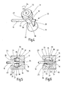
- this In the inserted state of the shrink sleeve 17, this is releasably connected to the feed sleeve 12 by means of a locking device 30, which is located in the illustrations in Fig. 1, 2, 4 and 5 in a locking position in which the inserted shrink sleeve 17 is firmly locked in the receptacle 13 of the feed sleeve 12.
- the locking device 30 can be moved from this locking position into a in Fig. 6 only schematically indicated release position in which the shrink sleeve 17 is released in the receptacle 13 and pulled out of this in opposite directions for insertion and removed.
- the chuck sleeve 12 and the shrink sleeve 17 are formed for minimum quantity lubrication with central supply of coolant / lubricant via a central tube 18 at least into the shrink sleeve 17 inside.
- the locking device 30 is designed such that the shrink sleeve 17 is detachable in and out of the receptacle 13 when the tube 18 remaining in the feed sleeve 12 is removed. In this removal of the shrink sleeve 17 thus remains the tube 18 within the chuck sleeve 12 in the position shown in Fig. 1, wherein the tube 18 is still guided by the locking device 30, as will be explained later.
- an aerosol which consists of lubricant droplets finely distributed in air, is guided through a channel, which is formed inside the tube 18 and has a constant cross section, as far as possible to the cutting edges of an inserted tool.
- the centrally located tube 18 has over the entire length of the coolant / lubricant channel formed thereby a constant cross section without any deflections, bends od.
- the shrink sleeve 17 includes a central, by means of a thread 20 axially adjustable adjustment sleeve 21, the axial adjustment in adaptation to the in the shrink sleeve 17 is used tool, wherein the central passage 19 for the tube 18 is contained in this insertion sleeve 21.
- the locking device 30 includes in the chuck sleeve 12 a latch 31 which is movable in the chuck sleeve 12 between a locking position shown in FIG. 1, 2, 4 and 5 and a release position shown in FIG.
- the bolt 31 is used in its locking position of the locking of the inserted into the receptacle 13 shrink sleeve 17. The movement of the bolt 31 between this locking position and the release position in which the shrink sleeve 17 can be removed from the receptacle 13, by the axial course of the pipe 18th , which is and remains an integral part of the feed sleeve 12, not hindered.
- the bolt 31 extends transversely through the receptacle 13 and is rotatably adjustable about its longitudinal central axis 32 between the locking position and the release position. Serves for this purpose at a, in Fig. 1 located below the end of the bolt 31 provided tool engagement surface, z. B. a hexagon socket 33, in which a tool can be inserted, then the rotational adjustment z. B. at least about 90 ° clockwise according to arrow 34 in Fig. 4 can be rotated.
- the latch 31 includes a longitudinal center axis 22 of the receptacle 13 coaxial, transverse to its longitudinal central axis 32 first passage 35 in the form of a bore through which the tube 18 extends therethrough. The bore diameter is at least slightly larger than the outer diameter of the tube 18.
- the latch 31 includes a second passage 36 of about the same diameter, which is directed approximately at right angles to the first passage 35 and this crosses, so that both passages 35, 36 in the center merge into one another ,
- the longitudinal center axes of both passages 35 and 36 extend within a common transverse to the longitudinal central axis 32 of the bolt 31 radial plane.
- Two diametrically opposite, in Figs. 5 and 6 for better clarity due to 37 and 38 marked, quadrant areas between the two intersecting passages are removed, such that a rotational adjustment of the Bolt 31 in the direction of arrow 34 by an angle of at least about 90 ° relative to the passing and stationary tube 18 is possible.
- the bolt 31 is formed from a cylinder pin rotatably mounted in the chuck sleeve 12 about the longitudinal central axis 32, which has flats 39 and 40 on two diametrically opposite peripheral portions which are approximately parallel to each other and extend parallel to the longitudinal central axis 32 of the bolt 31.
- the first passage 35 opens at both ends in the flats 39, 40 and is aligned with its central axis to this approximately at right angles.
- the shrink sleeve 17 has on the insertion part 16 on an end fork 23, which is open in Fig. 1 to the left and is formed by two mutually parallel fork legs 24 and 25.
- the fork 23 When inserting the shrink sleeve 17 into the receptacle 13 of the chuck sleeve 12, the fork 23 with its fork legs 24, 25 engage over the latch 31 located in the release position and receive between the fork legs 24, 25.
- the fork 23 is provided with a diameter of the bolt 31 at least substantially corresponding and extending in the direction of the longitudinal central axis 32 bore such that the forks 24, 25 on the facing sides corresponding to the cylindrical shape of the bolt 31 adapted recesses 26 and 27, z. B.
- the bolt 31 is equipped with locking elements 41, 42 and 43 shown in Fig. 3, the z. B. consist of balls.
- Two latching elements 41, 42 are contained in a diametral bore 44 in a top plate 45 of the bolt 31.
- a spring 46 In the bore 44 is a spring 46, by means of which the locking elements 41st and 42 are acted upon by a radially outwardly directed spring force and pressed against the chuck sleeve 12.
- the chuck sleeve 12 includes at the level of the locking elements 41 to 43 inside a more than about 90 ° circumferential angle extending groove 47, in which engage the locking elements radially.
- the locking element 43 is seated in a recess 48 of the head disk 45.
- the two rotational positions of the bolt 31 corresponding to the locking position and release position are defined by the locking elements 41 to 43, which slide in the groove 47 and at the respective radially directed end wall hit the groove 47.
- the chuck sleeve 12 is surrounded in the region of the bolt 31 by a sleeve 28 which is provided in the region of the hexagon socket 33 with a bore 29 for the passage of a tool.
- Fig. 1, 2, 4 and 5 the state is shown in which in the receptacle 13 of the chuck sleeve 12, a shrink sleeve 17 is inserted with its plug 16 and locked by means of the locking device 30, which is in its locking position, that a secure axial grip is ensured.
- the fit between the bore 14 and the diameter of the male part 16 at the same time a backlash-free, secure attachment in the radial direction is ensured.
- Reliable torque transmission is also ensured by means of the between the fork legs 24, 25 positively engaging bolt 31. Furthermore, a large concentricity is ensured.
- the locking of the shrink sleeve 17 is ensured by the fact that the bolt 31 is positively received in the locking position shown in FIG.
- the bolt 31 is rotated by an inserted through the hole 29 in the hexagon socket 33 tool in the direction of arrow 34 by approximately 90 ° -Umfangswinkel, ie The locking position shown in Fig. 5 in the release position shown in Fig. 6.
- the flattening 39 measured from flattening 40 is smaller than the opening dimension of the fork 23 in the form of Transverse distance of the two fork legs 24, 25 from each other, so that in this release position shown in FIG.
- the shrink sleeve 17 is no longer locked and thus can be pulled out of the receptacle 13 of the feed sleeve 12.
- the tube 18 remains firmly on the chuck sleeve 12 and passes through the latch 31, in the locking position due to the passage through the first passage 35 and in the opposite rotated by about 90 ° release position Due to the schematically indicated slots in the two quadrant areas 37 and 38, via which the two passages 35, 36 are interconnected in the circumferential direction, relative to the fixed tube 18, this rotational operation of the bolt 31 between the locking position and the release position possible without causing the remaining in the chuck sleeve 12 tube 18 is disturbing in the way.
- the design thus makes it possible to place a rectilinear tube 18 required for optimal minimum quantity lubrication in the center of the chuck sleeve 12 and the shrink sleeve 17 and nevertheless to lock and unlock the inserted shrink sleeve 17 without the tube 18 is disturbing in the way.
- the chuck 10 thus allows a simple and quick change of the insert 15, in particular in the form of the shrink sleeve 17, without causing the tube 18 would have to be removed or is disturbing in any other way. In all, results for the chuck 10 a slim, compact design.
- the feed sleeve 12 may be formed as a machine-side in a feed there existing insert or instead directly on the machine side is receivable.
Landscapes
- Engineering & Computer Science (AREA)
- Mechanical Engineering (AREA)
- Gripping On Spindles (AREA)
- Auxiliary Devices For Machine Tools (AREA)
- Drilling Tools (AREA)
- Polishing Bodies And Polishing Tools (AREA)
- Muffle Furnaces And Rotary Kilns (AREA)
Applications Claiming Priority (1)
| Application Number | Priority Date | Filing Date | Title |
|---|---|---|---|
| DE102006002089A DE102006002089A1 (de) | 2006-01-17 | 2006-01-17 | Futter für drehantreibbare Werkzeuge |
Publications (3)
| Publication Number | Publication Date |
|---|---|
| EP1808246A2 true EP1808246A2 (fr) | 2007-07-18 |
| EP1808246A3 EP1808246A3 (fr) | 2008-08-27 |
| EP1808246B1 EP1808246B1 (fr) | 2010-02-17 |
Family
ID=38048004
Family Applications (1)
| Application Number | Title | Priority Date | Filing Date |
|---|---|---|---|
| EP06024977A Not-in-force EP1808246B1 (fr) | 2006-01-17 | 2006-12-02 | Mandrin pour outils rotatifs |
Country Status (4)
| Country | Link |
|---|---|
| EP (1) | EP1808246B1 (fr) |
| AT (1) | ATE457843T1 (fr) |
| DE (2) | DE102006002089A1 (fr) |
| ES (1) | ES2341477T3 (fr) |
Cited By (1)
| Publication number | Priority date | Publication date | Assignee | Title |
|---|---|---|---|---|
| US20170232566A1 (en) * | 2014-10-07 | 2017-08-17 | Bilz Werkzeugfabrik Gmbh & Co. Kg | Tool holder with fluid supply |
Citations (1)
| Publication number | Priority date | Publication date | Assignee | Title |
|---|---|---|---|---|
| EP1561539A1 (fr) | 2002-07-18 | 2005-08-10 | Horkos Corp | Porte-outil d'une machine-outil |
Family Cites Families (2)
| Publication number | Priority date | Publication date | Assignee | Title |
|---|---|---|---|---|
| DE4128446C1 (en) * | 1991-08-28 | 1992-08-13 | Mercedes-Benz Aktiengesellschaft, 7000 Stuttgart, De | Standard stem for rotary machining tools - has outer, precise fitting cylinder for setting into retaining aperture in spindle |
| DE4232790C1 (de) * | 1992-09-30 | 1994-02-10 | Daimler Benz Ag | Standardschaft für rotierende Bearbeitungswerkzeuge zur unmittelbaren Aufnahme in eine Arbeitsspindel einer Werkzeugmaschine |
-
2006
- 2006-01-17 DE DE102006002089A patent/DE102006002089A1/de not_active Withdrawn
- 2006-12-02 DE DE502006006163T patent/DE502006006163D1/de active Active
- 2006-12-02 ES ES06024977T patent/ES2341477T3/es active Active
- 2006-12-02 AT AT06024977T patent/ATE457843T1/de active
- 2006-12-02 EP EP06024977A patent/EP1808246B1/fr not_active Not-in-force
Patent Citations (1)
| Publication number | Priority date | Publication date | Assignee | Title |
|---|---|---|---|---|
| EP1561539A1 (fr) | 2002-07-18 | 2005-08-10 | Horkos Corp | Porte-outil d'une machine-outil |
Cited By (2)
| Publication number | Priority date | Publication date | Assignee | Title |
|---|---|---|---|---|
| US20170232566A1 (en) * | 2014-10-07 | 2017-08-17 | Bilz Werkzeugfabrik Gmbh & Co. Kg | Tool holder with fluid supply |
| US10207331B2 (en) * | 2014-10-07 | 2019-02-19 | Bilz Werkzeugfabrik Gmbh & Co. Kg | Tool holder with fluid supply |
Also Published As
| Publication number | Publication date |
|---|---|
| EP1808246A3 (fr) | 2008-08-27 |
| DE502006006163D1 (de) | 2010-04-01 |
| ES2341477T3 (es) | 2010-06-21 |
| DE102006002089A1 (de) | 2007-07-19 |
| EP1808246B1 (fr) | 2010-02-17 |
| ATE457843T1 (de) | 2010-03-15 |
Similar Documents
| Publication | Publication Date | Title |
|---|---|---|
| DE102013103937B4 (de) | Schnellwechselsystem für eine Werkzeugaufnahme | |
| EP1504836B1 (fr) | Mandrin à changement rapide | |
| EP2318166B1 (fr) | Outil pour l'usinage par enlèvement de copeaux d'une pièce à usiner | |
| EP2370222B1 (fr) | Porte-outil | |
| EP1166932A1 (fr) | Broche de une machine-outil | |
| DE3031216C2 (de) | Spannfutter für Gewindebohrer | |
| DE102009044994B4 (de) | Schneidwerkzeug mit austauschbarem Schneideinsatz, Schneideinsatzträger, Verfahren zum Befestigen eines austauschbaren Schneideinsatzes, Verfahren zum Austauschen eines Schneideinsatzes | |
| DE10259959A1 (de) | Kraftspannfutter und Keilstange dafür | |
| DE102007043953B4 (de) | Spannvorrichtung zum axialen Spannen zweier voneinander lösbarer Maschinenbauteile | |
| EP3016770B2 (fr) | Système de tête interchangeable pour l'usinage de métaux | |
| DE102009044995B4 (de) | Schneideinsatzträger, Schneideinsatzund drehangetriebenes Schneidwerkzeug | |
| DE102011116572B4 (de) | Spannvorrichtung und Werkzeughalter mit einer derartigen Spannvorrichtung | |
| EP0129116B1 (fr) | Outil à fraiser vers l'avant et vers l'arrière | |
| DE8422976U1 (de) | Werkzeughalter mit Radialverstellvorrichtung für ein Werkzeug, insbesondere ein rotierendes Werkzeug | |
| EP1808246B1 (fr) | Mandrin pour outils rotatifs | |
| DE3532842A1 (de) | Fraes- und/oder bohrmaschine | |
| EP3890910B1 (fr) | Tête de forage pour le pochage de contours intérieurs non cylindriques | |
| DE102019100072A1 (de) | Ausziehbare Spannvorrichtung und Spanneinheit mit einer solchen Spannvorrichtung | |
| DE1959770C3 (de) | Gewindeschneidfutter | |
| DE102023200289B4 (de) | Vorrichtung, welche ein Rotationswerkzeug aufweist, und Verfahren zum Befestigen oder Lösen eines Schneideinsatzes bei einer solchen Vorrichtung | |
| DE9104377U1 (de) | Spannfutter für Schäfte | |
| WO1999024200A1 (fr) | Raccord rapide pour outils de foreuse a pointes de diamants, en particulier pour outils de foreuse a carottage (raccord rapide de couronne de forage) | |
| DE8605002U1 (de) | Schnellwechselfutter für Werkzeuge | |
| DE102022118797B3 (de) | Bohranschlag | |
| DE19837147C5 (de) | Spannfutter für Werkzeugmaschinen |
Legal Events
| Date | Code | Title | Description |
|---|---|---|---|
| PUAI | Public reference made under article 153(3) epc to a published international application that has entered the european phase |
Free format text: ORIGINAL CODE: 0009012 |
|
| AK | Designated contracting states |
Kind code of ref document: A2 Designated state(s): AT BE BG CH CY CZ DE DK EE ES FI FR GB GR HU IE IS IT LI LT LU LV MC NL PL PT RO SE SI SK TR |
|
| AX | Request for extension of the european patent |
Extension state: AL BA HR MK YU |
|
| PUAL | Search report despatched |
Free format text: ORIGINAL CODE: 0009013 |
|
| AK | Designated contracting states |
Kind code of ref document: A3 Designated state(s): AT BE BG CH CY CZ DE DK EE ES FI FR GB GR HU IE IS IT LI LT LU LV MC NL PL PT RO SE SI SK TR |
|
| AX | Request for extension of the european patent |
Extension state: AL BA HR MK RS |
|
| 17P | Request for examination filed |
Effective date: 20080903 |
|
| 17Q | First examination report despatched |
Effective date: 20081106 |
|
| AKX | Designation fees paid |
Designated state(s): AT BE BG CH CY CZ DE DK EE ES FI FR GB GR HU IE IS IT LI LT LU LV MC NL PL PT RO SE SI SK TR |
|
| GRAP | Despatch of communication of intention to grant a patent |
Free format text: ORIGINAL CODE: EPIDOSNIGR1 |
|
| GRAS | Grant fee paid |
Free format text: ORIGINAL CODE: EPIDOSNIGR3 |
|
| GRAA | (expected) grant |
Free format text: ORIGINAL CODE: 0009210 |
|
| AK | Designated contracting states |
Kind code of ref document: B1 Designated state(s): AT BE BG CH CY CZ DE DK EE ES FI FR GB GR HU IE IS IT LI LT LU LV MC NL PL PT RO SE SI SK TR |
|
| REG | Reference to a national code |
Ref country code: GB Ref legal event code: FG4D Free format text: NOT ENGLISH |
|
| REG | Reference to a national code |
Ref country code: CH Ref legal event code: EP |
|
| REG | Reference to a national code |
Ref country code: IE Ref legal event code: FG4D Free format text: LANGUAGE OF EP DOCUMENT: GERMAN |
|
| REF | Corresponds to: |
Ref document number: 502006006163 Country of ref document: DE Date of ref document: 20100401 Kind code of ref document: P |
|
| REG | Reference to a national code |
Ref country code: SE Ref legal event code: TRGR |
|
| REG | Reference to a national code |
Ref country code: ES Ref legal event code: FG2A Ref document number: 2341477 Country of ref document: ES Kind code of ref document: T3 |
|
| REG | Reference to a national code |
Ref country code: NL Ref legal event code: VDEP Effective date: 20100217 |
|
| LTIE | Lt: invalidation of european patent or patent extension |
Effective date: 20100217 |
|
| PG25 | Lapsed in a contracting state [announced via postgrant information from national office to epo] |
Ref country code: PT Free format text: LAPSE BECAUSE OF FAILURE TO SUBMIT A TRANSLATION OF THE DESCRIPTION OR TO PAY THE FEE WITHIN THE PRESCRIBED TIME-LIMIT Effective date: 20100617 Ref country code: LT Free format text: LAPSE BECAUSE OF FAILURE TO SUBMIT A TRANSLATION OF THE DESCRIPTION OR TO PAY THE FEE WITHIN THE PRESCRIBED TIME-LIMIT Effective date: 20100217 Ref country code: IS Free format text: LAPSE BECAUSE OF FAILURE TO SUBMIT A TRANSLATION OF THE DESCRIPTION OR TO PAY THE FEE WITHIN THE PRESCRIBED TIME-LIMIT Effective date: 20100617 |
|
| PG25 | Lapsed in a contracting state [announced via postgrant information from national office to epo] |
Ref country code: SI Free format text: LAPSE BECAUSE OF FAILURE TO SUBMIT A TRANSLATION OF THE DESCRIPTION OR TO PAY THE FEE WITHIN THE PRESCRIBED TIME-LIMIT Effective date: 20100217 Ref country code: PL Free format text: LAPSE BECAUSE OF FAILURE TO SUBMIT A TRANSLATION OF THE DESCRIPTION OR TO PAY THE FEE WITHIN THE PRESCRIBED TIME-LIMIT Effective date: 20100217 Ref country code: LV Free format text: LAPSE BECAUSE OF FAILURE TO SUBMIT A TRANSLATION OF THE DESCRIPTION OR TO PAY THE FEE WITHIN THE PRESCRIBED TIME-LIMIT Effective date: 20100217 Ref country code: FI Free format text: LAPSE BECAUSE OF FAILURE TO SUBMIT A TRANSLATION OF THE DESCRIPTION OR TO PAY THE FEE WITHIN THE PRESCRIBED TIME-LIMIT Effective date: 20100217 |
|
| REG | Reference to a national code |
Ref country code: IE Ref legal event code: FD4D |
|
| PG25 | Lapsed in a contracting state [announced via postgrant information from national office to epo] |
Ref country code: EE Free format text: LAPSE BECAUSE OF FAILURE TO SUBMIT A TRANSLATION OF THE DESCRIPTION OR TO PAY THE FEE WITHIN THE PRESCRIBED TIME-LIMIT Effective date: 20100217 Ref country code: RO Free format text: LAPSE BECAUSE OF FAILURE TO SUBMIT A TRANSLATION OF THE DESCRIPTION OR TO PAY THE FEE WITHIN THE PRESCRIBED TIME-LIMIT Effective date: 20100217 Ref country code: CY Free format text: LAPSE BECAUSE OF FAILURE TO SUBMIT A TRANSLATION OF THE DESCRIPTION OR TO PAY THE FEE WITHIN THE PRESCRIBED TIME-LIMIT Effective date: 20100217 Ref country code: GR Free format text: LAPSE BECAUSE OF FAILURE TO SUBMIT A TRANSLATION OF THE DESCRIPTION OR TO PAY THE FEE WITHIN THE PRESCRIBED TIME-LIMIT Effective date: 20100518 Ref country code: IE Free format text: LAPSE BECAUSE OF FAILURE TO SUBMIT A TRANSLATION OF THE DESCRIPTION OR TO PAY THE FEE WITHIN THE PRESCRIBED TIME-LIMIT Effective date: 20100217 Ref country code: NL Free format text: LAPSE BECAUSE OF FAILURE TO SUBMIT A TRANSLATION OF THE DESCRIPTION OR TO PAY THE FEE WITHIN THE PRESCRIBED TIME-LIMIT Effective date: 20100217 |
|
| PG25 | Lapsed in a contracting state [announced via postgrant information from national office to epo] |
Ref country code: SK Free format text: LAPSE BECAUSE OF FAILURE TO SUBMIT A TRANSLATION OF THE DESCRIPTION OR TO PAY THE FEE WITHIN THE PRESCRIBED TIME-LIMIT Effective date: 20100217 Ref country code: CZ Free format text: LAPSE BECAUSE OF FAILURE TO SUBMIT A TRANSLATION OF THE DESCRIPTION OR TO PAY THE FEE WITHIN THE PRESCRIBED TIME-LIMIT Effective date: 20100217 Ref country code: BG Free format text: LAPSE BECAUSE OF FAILURE TO SUBMIT A TRANSLATION OF THE DESCRIPTION OR TO PAY THE FEE WITHIN THE PRESCRIBED TIME-LIMIT Effective date: 20100517 |
|
| PLBE | No opposition filed within time limit |
Free format text: ORIGINAL CODE: 0009261 |
|
| STAA | Information on the status of an ep patent application or granted ep patent |
Free format text: STATUS: NO OPPOSITION FILED WITHIN TIME LIMIT |
|
| 26N | No opposition filed |
Effective date: 20101118 |
|
| PG25 | Lapsed in a contracting state [announced via postgrant information from national office to epo] |
Ref country code: DK Free format text: LAPSE BECAUSE OF FAILURE TO SUBMIT A TRANSLATION OF THE DESCRIPTION OR TO PAY THE FEE WITHIN THE PRESCRIBED TIME-LIMIT Effective date: 20100217 |
|
| BERE | Be: lapsed |
Owner name: BILZ WERKZEUGFABRIK G.M.B.H. & CO. KG Effective date: 20101231 |
|
| PG25 | Lapsed in a contracting state [announced via postgrant information from national office to epo] |
Ref country code: MC Free format text: LAPSE BECAUSE OF NON-PAYMENT OF DUE FEES Effective date: 20101231 |
|
| REG | Reference to a national code |
Ref country code: CH Ref legal event code: PL |
|
| PG25 | Lapsed in a contracting state [announced via postgrant information from national office to epo] |
Ref country code: BE Free format text: LAPSE BECAUSE OF NON-PAYMENT OF DUE FEES Effective date: 20101231 |
|
| PG25 | Lapsed in a contracting state [announced via postgrant information from national office to epo] |
Ref country code: LI Free format text: LAPSE BECAUSE OF NON-PAYMENT OF DUE FEES Effective date: 20101231 Ref country code: CH Free format text: LAPSE BECAUSE OF NON-PAYMENT OF DUE FEES Effective date: 20101231 |
|
| PG25 | Lapsed in a contracting state [announced via postgrant information from national office to epo] |
Ref country code: LU Free format text: LAPSE BECAUSE OF NON-PAYMENT OF DUE FEES Effective date: 20101202 Ref country code: HU Free format text: LAPSE BECAUSE OF FAILURE TO SUBMIT A TRANSLATION OF THE DESCRIPTION OR TO PAY THE FEE WITHIN THE PRESCRIBED TIME-LIMIT Effective date: 20100818 |
|
| PG25 | Lapsed in a contracting state [announced via postgrant information from national office to epo] |
Ref country code: TR Free format text: LAPSE BECAUSE OF FAILURE TO SUBMIT A TRANSLATION OF THE DESCRIPTION OR TO PAY THE FEE WITHIN THE PRESCRIBED TIME-LIMIT Effective date: 20100217 |
|
| REG | Reference to a national code |
Ref country code: DE Ref legal event code: R082 Ref document number: 502006006163 Country of ref document: DE Representative=s name: WITTE, WELLER & PARTNER, DE Ref country code: DE Ref legal event code: R082 Ref document number: 502006006163 Country of ref document: DE Representative=s name: WITTE, WELLER & PARTNER PATENTANWAELTE MBB, DE |
|
| REG | Reference to a national code |
Ref country code: FR Ref legal event code: PLFP Year of fee payment: 10 |
|
| PGFP | Annual fee paid to national office [announced via postgrant information from national office to epo] |
Ref country code: GB Payment date: 20151221 Year of fee payment: 10 |
|
| PGFP | Annual fee paid to national office [announced via postgrant information from national office to epo] |
Ref country code: SE Payment date: 20151221 Year of fee payment: 10 Ref country code: FR Payment date: 20151221 Year of fee payment: 10 Ref country code: ES Payment date: 20151214 Year of fee payment: 10 Ref country code: AT Payment date: 20151222 Year of fee payment: 10 |
|
| PGFP | Annual fee paid to national office [announced via postgrant information from national office to epo] |
Ref country code: IT Payment date: 20151228 Year of fee payment: 10 Ref country code: DE Payment date: 20160203 Year of fee payment: 10 |
|
| REG | Reference to a national code |
Ref country code: DE Ref legal event code: R119 Ref document number: 502006006163 Country of ref document: DE |
|
| REG | Reference to a national code |
Ref country code: SE Ref legal event code: EUG |
|
| REG | Reference to a national code |
Ref country code: AT Ref legal event code: MM01 Ref document number: 457843 Country of ref document: AT Kind code of ref document: T Effective date: 20161202 |
|
| GBPC | Gb: european patent ceased through non-payment of renewal fee |
Effective date: 20161202 |
|
| PG25 | Lapsed in a contracting state [announced via postgrant information from national office to epo] |
Ref country code: SE Free format text: LAPSE BECAUSE OF NON-PAYMENT OF DUE FEES Effective date: 20161203 |
|
| REG | Reference to a national code |
Ref country code: FR Ref legal event code: ST Effective date: 20170831 |
|
| PG25 | Lapsed in a contracting state [announced via postgrant information from national office to epo] |
Ref country code: AT Free format text: LAPSE BECAUSE OF NON-PAYMENT OF DUE FEES Effective date: 20161202 Ref country code: IT Free format text: LAPSE BECAUSE OF NON-PAYMENT OF DUE FEES Effective date: 20161202 Ref country code: FR Free format text: LAPSE BECAUSE OF NON-PAYMENT OF DUE FEES Effective date: 20170102 |
|
| PG25 | Lapsed in a contracting state [announced via postgrant information from national office to epo] |
Ref country code: DE Free format text: LAPSE BECAUSE OF NON-PAYMENT OF DUE FEES Effective date: 20170701 Ref country code: GB Free format text: LAPSE BECAUSE OF NON-PAYMENT OF DUE FEES Effective date: 20161202 |
|
| PG25 | Lapsed in a contracting state [announced via postgrant information from national office to epo] |
Ref country code: ES Free format text: LAPSE BECAUSE OF NON-PAYMENT OF DUE FEES Effective date: 20161203 |
|
| REG | Reference to a national code |
Ref country code: ES Ref legal event code: FD2A Effective date: 20181121 |