EP1808280A2 - Utilisation de procédés d'oxydation avancés pour remédier aux sols et sédiments contaminés par des métaux lourds et des radionucléides dans une boucle de processus fermée - Google Patents
Utilisation de procédés d'oxydation avancés pour remédier aux sols et sédiments contaminés par des métaux lourds et des radionucléides dans une boucle de processus fermée Download PDFInfo
- Publication number
- EP1808280A2 EP1808280A2 EP07000013A EP07000013A EP1808280A2 EP 1808280 A2 EP1808280 A2 EP 1808280A2 EP 07000013 A EP07000013 A EP 07000013A EP 07000013 A EP07000013 A EP 07000013A EP 1808280 A2 EP1808280 A2 EP 1808280A2
- Authority
- EP
- European Patent Office
- Prior art keywords
- die
- accordance
- valve
- under pressure
- breather
- Prior art date
- Legal status (The legal status is an assumption and is not a legal conclusion. Google has not performed a legal analysis and makes no representation as to the accuracy of the status listed.)
- Withdrawn
Links
Images
Classifications
-
- B—PERFORMING OPERATIONS; TRANSPORTING
- B29—WORKING OF PLASTICS; WORKING OF SUBSTANCES IN A PLASTIC STATE IN GENERAL
- B29C—SHAPING OR JOINING OF PLASTICS; SHAPING OF MATERIAL IN A PLASTIC STATE, NOT OTHERWISE PROVIDED FOR; AFTER-TREATMENT OF THE SHAPED PRODUCTS, e.g. REPAIRING
- B29C41/00—Shaping by coating a mould, core or other substrate, i.e. by depositing material and stripping-off the shaped article; Apparatus therefor
- B29C41/02—Shaping by coating a mould, core or other substrate, i.e. by depositing material and stripping-off the shaped article; Apparatus therefor for making articles of definite length, i.e. discrete articles
- B29C41/04—Rotational or centrifugal casting, i.e. coating the inside of a mould by rotating the mould
-
- B—PERFORMING OPERATIONS; TRANSPORTING
- B29—WORKING OF PLASTICS; WORKING OF SUBSTANCES IN A PLASTIC STATE IN GENERAL
- B29C—SHAPING OR JOINING OF PLASTICS; SHAPING OF MATERIAL IN A PLASTIC STATE, NOT OTHERWISE PROVIDED FOR; AFTER-TREATMENT OF THE SHAPED PRODUCTS, e.g. REPAIRING
- B29C33/00—Moulds or cores; Details thereof or accessories therefor
- B29C33/10—Moulds or cores; Details thereof or accessories therefor with incorporated venting means
-
- B—PERFORMING OPERATIONS; TRANSPORTING
- B29—WORKING OF PLASTICS; WORKING OF SUBSTANCES IN A PLASTIC STATE IN GENERAL
- B29C—SHAPING OR JOINING OF PLASTICS; SHAPING OF MATERIAL IN A PLASTIC STATE, NOT OTHERWISE PROVIDED FOR; AFTER-TREATMENT OF THE SHAPED PRODUCTS, e.g. REPAIRING
- B29C41/00—Shaping by coating a mould, core or other substrate, i.e. by depositing material and stripping-off the shaped article; Apparatus therefor
- B29C41/34—Component parts, details or accessories; Auxiliary operations
-
- Y—GENERAL TAGGING OF NEW TECHNOLOGICAL DEVELOPMENTS; GENERAL TAGGING OF CROSS-SECTIONAL TECHNOLOGIES SPANNING OVER SEVERAL SECTIONS OF THE IPC; TECHNICAL SUBJECTS COVERED BY FORMER USPC CROSS-REFERENCE ART COLLECTIONS [XRACs] AND DIGESTS
- Y10—TECHNICAL SUBJECTS COVERED BY FORMER USPC
- Y10S—TECHNICAL SUBJECTS COVERED BY FORMER USPC CROSS-REFERENCE ART COLLECTIONS [XRACs] AND DIGESTS
- Y10S425/00—Plastic article or earthenware shaping or treating: apparatus
- Y10S425/812—Venting
Definitions
- This invention relates to a die with controlled breather for use in rotational pressing.
- the breather is usually a simple hole, often with a tube, which puts the interior of the die in communication with the external environment.
- filters are inserted, very often consisting of steel wool.
- the still powdered plastic material ends up by depositing on the filter, then melting and solidifying during cooling. This leads in a short time to obstruction of the breather.
- the general purpose of this invention is to remedy the above-mentioned shortcomings by making available a more efficient breather system with innovative characteristics.
- a rotational die including a breather device for connection of the interior of the die with the exterior and characterized in that said device includes a passage between the interior and the exterior of the die which is equipped with a valve operated by an actuator piloted by a handling controller for opening a passage after a first step of the pressing process.
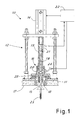
- FIG 1 shows partially a rotational die with breather system in accordance with this invention.
- the die is designated as a whole by reference number 10 and includes a die shell 11 and at least one controlled breather device 12.
- the controlled breather system includes in turn a breather valve equipped with a shutter 13 which is movable between a closed position (shown in solid lines) and an open position (shown in broken lines) by means of an actuator 14 (controlled by a suitable controller 22).
- the actuator 14 is connected to the shutter 13 by means of a control rod 15 which crosses sealed a valve body 16 facing inward 17 of the die to realize a striking seat 18 for valve 13 when in closed position.
- the shutter 13 has a closing surface which is conical and tapers towards the outside of the die.
- the valve has the control rod 15 which is pierced axially at 19 and has radial passages 20 inside the valve body and at least one breather opening 21 on the outside. In this manner, when the valve is moved into open position there is communication between the inside of the die and the external environment through the passages 20, the axial duct 19 and the external passage 21.
- a thermal probe connected to the controller 22 to project from the valve into the die and detect the temperature inside the die.
- the source is connected to the body 16 to inject air into the chamber 25 of the valve so that the air under pressure enters on command into the die when the valve is open and passes through the valve opening.
- the breather remains closed so as to avoid plastic material not yet completely melted from coming out of the die.
- the controller 22 After reaching a predetermined breather condition (for example, a desired temperature set by the operator and detected by the sensor) the controller 22 opens the breather to allow passage of the gases outward.
- a predetermined breather condition for example, a desired temperature set by the operator and detected by the sensor
- inlet of air through the source 24 also allows expulsion of the pressed article from the die.
- a large quantity of air is injected into the pressed part which, due to the effect of the pressure generated, is expelled from the die.
- part cooling step it is also possible to inject low-pressure air, for example, in case of pressed parts with very broad flat parts to avoid deformation and humps. Cooling is also accelerated.
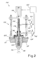
- FIG 2 show a second realization of a die realized in accordance with the principles of this invention.
- the realization of FIG 2 has parts similar to those of the realization of FIG 1 which are indicated with the same number increased by 100.
- the die of FIG 2 designated as a whole by reference number 110 and which includes a die shell 111 and at least one controlled breather device 112 which includes in turn a breather valve having a shutter 113 operated by an actuator 114 through a control rod 115 which traverses sealed a valve body 116.
- the valve body has a seat 118 as striker of the shutter 113 projecting from the wall 117 of the interior of the die.
- the control rod 115 is pierced axially by a duct 119 and has radial passages 120 immediately before the shutter 113.
- the duct 119 is connected to a controlled valve 130 for its alternative connection to a discharge 121 or to a source of compressed air 131.
- the chamber 125 inside the body 116 for passage of the breather valve rod is connected to a controlled valve 132 for its alternative connection to a discharge 134 or to a source of compressed air 124.
- the valves 130, 132 and the actuator 114 are controlled by a controller 122, realizable for example (like the controller 22) with an appropriately programmed PLC as readily imaginable for one skilled in the art.
- the breather In use, during the initial heating of the pressed part the breather remains closed as shown in solid lines in FIG 2 so as to avoid the still not completely melted plastic's coming out of the die.
- the controller 122 After reaching the predetermined conditions for opening of the breather (for example, a predetermined temperature) the controller 122 opens the breather commanding the actuator 114 (as shown in broken lines in FIG 2) and operating one of the valves 130, 132 for discharge, allowing leaking out of the gases. The plastic can no longer come out being completely melted.
- the controller commands the valve 130 to inject low-pressure air into the die while it commands the other valve 132 for discharging it.
- this operation allows avoiding deformations and humps.
- cooling is accelerated.
- the controller can also command the valve 132 to inject air under pressure into the pressed part which, due to the effect of the pressure generated, is expelled from the die.
- the breather can be activated and create communication between the inside and the outside at the desired moment or under a determined condition, for example, of temperature.
- the operations of cleaning of the passage hole are also avoided since, remaining closed in the first die-heating step, it does not allow the still dusty plastic material to enter into the hole.
- filters and their maintenance necessary.
- the function of expeller of the pressed part can also be performed and allow injection of air in the cooling step to accelerate the pressing operations. The possibility of injecting air under pressure in the cooling step allows reducing or avoiding humps and deformation.
- valve also allows detection of internal parameters of the die as, for example, air temperature.
- internal parameters of the die as, for example, air temperature.
- the alternative use of the radial passages in the rod or the mouth 18, 118 of the valve body allows blowing air under pressure between walls of the die and the part or inside the part.
- the rotational structure of the die can be of any known type and it has not been shown since it is readily imaginable to one skilled in the art.
- sources of appropriate gases under pressure This allows, for example, injection of inert gases into the die during pressing of materials sensitive to air oxidation.
- the programmed sequence of connection to the sources and discharges made by the controller can be different from that described above.
Landscapes
- Engineering & Computer Science (AREA)
- Mechanical Engineering (AREA)
- Moulds For Moulding Plastics Or The Like (AREA)
- Extrusion Moulding Of Plastics Or The Like (AREA)
- Injection Moulding Of Plastics Or The Like (AREA)
- Perforating, Stamping-Out Or Severing By Means Other Than Cutting (AREA)
- Moulding By Coating Moulds (AREA)
Applications Claiming Priority (1)
| Application Number | Priority Date | Filing Date | Title |
|---|---|---|---|
| IT000055A ITMI20060055A1 (it) | 2006-01-16 | 2006-01-16 | Stampo con sfiato comandato per stampaggio rotazionale |
Publications (2)
| Publication Number | Publication Date |
|---|---|
| EP1808280A2 true EP1808280A2 (fr) | 2007-07-18 |
| EP1808280A3 EP1808280A3 (fr) | 2008-06-25 |
Family
ID=37963581
Family Applications (1)
| Application Number | Title | Priority Date | Filing Date |
|---|---|---|---|
| EP07000013A Withdrawn EP1808280A3 (fr) | 2006-01-16 | 2007-01-02 | Moule avec event controlé pour rotomoulage |
Country Status (3)
| Country | Link |
|---|---|
| US (1) | US7677876B2 (fr) |
| EP (1) | EP1808280A3 (fr) |
| IT (1) | ITMI20060055A1 (fr) |
Cited By (2)
| Publication number | Priority date | Publication date | Assignee | Title |
|---|---|---|---|---|
| EP2428343A1 (fr) * | 2010-09-13 | 2012-03-14 | Compagnie Plastic Omnium | Moule pour le rotomoulage muni d'un système d'éventation |
| IT202100014591A1 (it) * | 2021-06-04 | 2022-12-04 | Persico Spa | Processo di stampaggio rotazionale e relativo stampo per stampaggio rotazionale comprendente un dispositivo di sfiato |
Family Cites Families (11)
| Publication number | Priority date | Publication date | Assignee | Title |
|---|---|---|---|---|
| US3914361A (en) * | 1972-06-29 | 1975-10-21 | Furukawa Electric Co Ltd | Method for rotational molding of composite foamed plastic articles |
| JPS6149819A (ja) * | 1984-08-20 | 1986-03-11 | Shokichi Hayashi | 金型のガス抜き装置 |
| CA1264521A (fr) * | 1985-12-24 | 1990-01-23 | Minoru Kuriyama | Appareil degazeur pour moule de coulee du metal |
| EP0281877B1 (fr) * | 1987-03-13 | 1992-06-03 | Ube Industries, Ltd. | Appareil de dégazer pour un moule de métal |
| US5688270A (en) | 1993-07-22 | 1997-11-18 | Ethicon Endo-Surgery,Inc. | Electrosurgical hemostatic device with recessed and/or offset electrodes |
| DE4428984C2 (de) * | 1994-08-16 | 2002-12-12 | Elkamet Kunststofftechnik Gmbh | Vorrichtung zum Herstellen von Hohlkörpern aus rieselfähigen trockenen thermoplastischen Kunststoffen durch Rotationsschmelzen |
| GB9421596D0 (en) * | 1994-10-22 | 1994-12-14 | Univ Belfast | A method of and apparatus for rotational moulding |
| AU691708B2 (en) * | 1995-01-19 | 1998-05-21 | Automated Plastic Systems Pty Ltd | Introducing powder to a rotating mould |
| US6367765B1 (en) * | 1999-09-09 | 2002-04-09 | Klaus A. Wieder | Mold vent |
| US7114944B2 (en) * | 2004-01-21 | 2006-10-03 | David Wolfe Design, Inc | Tactical venting |
| US7481642B2 (en) * | 2004-04-23 | 2009-01-27 | Husky Injection Molding Systems Ltd. | Method and apparatus for controlling a vent gap with active material elements |
-
2006
- 2006-01-16 IT IT000055A patent/ITMI20060055A1/it unknown
-
2007
- 2007-01-02 EP EP07000013A patent/EP1808280A3/fr not_active Withdrawn
- 2007-01-16 US US11/653,367 patent/US7677876B2/en active Active
Cited By (5)
| Publication number | Priority date | Publication date | Assignee | Title |
|---|---|---|---|---|
| EP2428343A1 (fr) * | 2010-09-13 | 2012-03-14 | Compagnie Plastic Omnium | Moule pour le rotomoulage muni d'un système d'éventation |
| FR2964589A1 (fr) * | 2010-09-13 | 2012-03-16 | Plastic Omnium Cie | Moule muni d'un systeme d'eventation |
| IT202100014591A1 (it) * | 2021-06-04 | 2022-12-04 | Persico Spa | Processo di stampaggio rotazionale e relativo stampo per stampaggio rotazionale comprendente un dispositivo di sfiato |
| WO2022254471A1 (fr) * | 2021-06-04 | 2022-12-08 | Persico S.P.A. | Procédé de rotomoulage et moule associé pour rotomoulage comprenant un dispositif de mise à l'air libre |
| EP4494834A1 (fr) * | 2021-06-04 | 2025-01-22 | Persico S.p.A. | Procédé de rotomoulage et moule associé pour rotomoulage comprenant un dispositif de mise à l'air libre |
Also Published As
| Publication number | Publication date |
|---|---|
| US20070166424A1 (en) | 2007-07-19 |
| US7677876B2 (en) | 2010-03-16 |
| EP1808280A3 (fr) | 2008-06-25 |
| ITMI20060055A1 (it) | 2007-07-17 |
Similar Documents
| Publication | Publication Date | Title |
|---|---|---|
| CN105121027B (zh) | 粉末输送设备和相关联的操作方法 | |
| CN101903662B (zh) | 真空产生装置及其工作方法 | |
| JPS61192531A (ja) | 鋳型空洞内作動圧制御装置と方法 | |
| US7677876B2 (en) | Die with controlled breather for rotational pressing | |
| US20220228897A1 (en) | Dosing unit and method for dosing a liquid | |
| US20060185586A1 (en) | Powder conveying pump | |
| CN102279119B (zh) | 一种高温烟气检测取样系统 | |
| CN105818324A (zh) | 用于塑料材料的注射模制的系统及方法 | |
| JP2013035019A (ja) | Pfダイカスト装置用減圧・酸素充填装置 | |
| JP2002347073A (ja) | 真空ホッパーによる射出成形機の材料樹脂供給装置 | |
| EP2947042B1 (fr) | Dispositif de levage pour une roue ou pneu | |
| US6183682B1 (en) | Method for preventing occurrence of impact pressure in injection molding machine | |
| EP2164352B1 (fr) | Dispositif de mesure de la résistance au tirage | |
| US20130149049A1 (en) | Blind rivet drawing mandrel removal device | |
| JP7388037B2 (ja) | ダイカストマシンの制御装置、制御パラメータの設定に用いられる指標値を取得する装置および方法 | |
| KR101814413B1 (ko) | 사출성형기 설치형 금형 진공 및 가압 제어시스템 | |
| US6082438A (en) | Method and system for the control of a vacuum valve of a vacuum die casting machine | |
| JP2000146454A (ja) | 溶解精錬炉における副原料投入装置 | |
| JP2001341124A (ja) | 成形原料脱気方法及び成形原料脱気装置 | |
| JP5308776B2 (ja) | 射出成形金型用気体吸引装置 | |
| JP2012035417A (ja) | 射出装置 | |
| KR101397516B1 (ko) | 제품 출하부 에어 나이프 챔버 | |
| KR101835048B1 (ko) | Pet 더스트 배출 시스템이 구비된 사출 금형 | |
| JP2002310474A (ja) | アイソレータからの物品排出装置 | |
| KR20120034091A (ko) | 가네트 블라스팅 장치 |
Legal Events
| Date | Code | Title | Description |
|---|---|---|---|
| PUAI | Public reference made under article 153(3) epc to a published international application that has entered the european phase |
Free format text: ORIGINAL CODE: 0009012 |
|
| AK | Designated contracting states |
Kind code of ref document: A2 Designated state(s): AT BE BG CH CY CZ DE DK EE ES FI FR GB GR HU IE IS IT LI LT LU LV MC NL PL PT RO SE SI SK TR |
|
| AX | Request for extension of the european patent |
Extension state: AL BA HR MK YU |
|
| PUAL | Search report despatched |
Free format text: ORIGINAL CODE: 0009013 |
|
| AK | Designated contracting states |
Kind code of ref document: A3 Designated state(s): AT BE BG CH CY CZ DE DK EE ES FI FR GB GR HU IE IS IT LI LT LU LV MC NL PL PT RO SE SI SK TR |
|
| AX | Request for extension of the european patent |
Extension state: AL BA HR MK RS |
|
| AKX | Designation fees paid | ||
| REG | Reference to a national code |
Ref country code: DE Ref legal event code: 8566 |
|
| STAA | Information on the status of an ep patent application or granted ep patent |
Free format text: STATUS: THE APPLICATION IS DEEMED TO BE WITHDRAWN |
|
| 18D | Application deemed to be withdrawn |
Effective date: 20081230 |