EP1808403A2 - Chariot de manutention avec un bloc d'alimentation remplaçable - Google Patents
Chariot de manutention avec un bloc d'alimentation remplaçable Download PDFInfo
- Publication number
- EP1808403A2 EP1808403A2 EP06027087A EP06027087A EP1808403A2 EP 1808403 A2 EP1808403 A2 EP 1808403A2 EP 06027087 A EP06027087 A EP 06027087A EP 06027087 A EP06027087 A EP 06027087A EP 1808403 A2 EP1808403 A2 EP 1808403A2
- Authority
- EP
- European Patent Office
- Prior art keywords
- supply unit
- power supply
- truck
- battery
- fixing
- Prior art date
- Legal status (The legal status is an assumption and is not a legal conclusion. Google has not performed a legal analysis and makes no representation as to the accuracy of the status listed.)
- Withdrawn
Links
Images
Classifications
-
- B—PERFORMING OPERATIONS; TRANSPORTING
- B66—HOISTING; LIFTING; HAULING
- B66F—HOISTING, LIFTING, HAULING OR PUSHING, NOT OTHERWISE PROVIDED FOR, e.g. DEVICES WHICH APPLY A LIFTING OR PUSHING FORCE DIRECTLY TO THE SURFACE OF A LOAD
- B66F9/00—Devices for lifting or lowering bulky or heavy goods for loading or unloading purposes
- B66F9/06—Devices for lifting or lowering bulky or heavy goods for loading or unloading purposes movable, with their loads, on wheels or the like, e.g. fork-lift trucks
- B66F9/075—Constructional features or details
- B66F9/07513—Details concerning the chassis
- B66F9/07531—Battery compartments
- B66F9/07536—Battery stoppers, i.e. means to hold battery in position
-
- B—PERFORMING OPERATIONS; TRANSPORTING
- B60—VEHICLES IN GENERAL
- B60K—ARRANGEMENT OR MOUNTING OF PROPULSION UNITS OR OF TRANSMISSIONS IN VEHICLES; ARRANGEMENT OR MOUNTING OF PLURAL DIVERSE PRIME-MOVERS IN VEHICLES; AUXILIARY DRIVES FOR VEHICLES; INSTRUMENTATION OR DASHBOARDS FOR VEHICLES; ARRANGEMENTS IN CONNECTION WITH COOLING, AIR INTAKE, GAS EXHAUST OR FUEL SUPPLY OF PROPULSION UNITS IN VEHICLES
- B60K1/00—Arrangement or mounting of electrical propulsion units
- B60K1/04—Arrangement or mounting of electrical propulsion units of the electric storage means for propulsion
-
- B—PERFORMING OPERATIONS; TRANSPORTING
- B60—VEHICLES IN GENERAL
- B60Y—INDEXING SCHEME RELATING TO ASPECTS CROSS-CUTTING VEHICLE TECHNOLOGY
- B60Y2200/00—Type of vehicle
- B60Y2200/10—Road Vehicles
- B60Y2200/15—Fork lift trucks, Industrial trucks
Definitions
- the invention relates to an industrial truck with an exchangeable power supply unit and a device for fixing the replaceable power supply unit in at least one direction of movement.
- interchangeable power units are often used instead of permanently installed devices such as internal combustion engines in combination with fuel tanks.
- these can be called power packs, i.
- Devices which have mostly similar dimensions as a replaceable battery and in which a fuel tank and a device for generating electrical energy from the fuel, in particular a fuel cell unit, are combined in one unit. If the energy reserves of the energy supply unit are exhausted, it can be directly exchanged for another energy supply unit with full inventories, so that the downtime of the truck is minimized.
- the power supply unit is usually arranged in a separate area of the truck, which is referred to as a battery compartment.
- the dimensions of the battery compartment are as compact as possible in order to make optimal use of the space available in the truck.
- it in order to enable a rapid change of the energy supply unit, it must be significantly larger than the largest energy supply unit to be introduced, since otherwise it will tilt too easily.
- the battery compartment must have certain minimum dimensions. Due to the distance of the power supply unit from the side walls of the battery compartment, the power supply unit can move in abrupt vehicle movements in relation to the battery compartment and strike for example on one of the side walls, which can lead to damage of the truck and / or the power supply unit. As the distance to the front or rear side walls of the battery compartment is particularly is large, especially movements of the power supply unit in the vehicle longitudinal direction are dangerous and must be prevented.
- the invention is therefore an object of the invention to provide an industrial truck with a replaceable power supply unit and a device for fixing the replaceable power supply unit in at least one direction of movement, with little effort a simple replacement of the power supply unit, possible independent of the dimensions of the power supply unit.
- This object is achieved in that the device for fixing the power supply unit is designed such that the power supply unit is automatically fixed. The time-consuming and error-prone fixation of the power supply unit by hand is eliminated.
- the device has at least one latching element, in particular a snap-in hook, arranged in the bottom area and / or at least one latching element, preferably oriented parallel to the vehicle longitudinal axis, of a battery compartment.
- the wall is any outer boundary of the battery compartment, especially the ceiling to see, even if it is broken structures such as grids or perforated plates.
- Latching elements such as latching hooks or latching lugs, are elements that allow in one direction a largely unrestrained movement, while in the opposite direction no movement is possible. The use of such locking elements thus allows desired movements, such as the insertion of the power supply unit, and prevents the unwanted countermovement, such as slipping out of the power supply unit.
- a movement of the battery parallel to the vehicle longitudinal direction is particularly harmful and can be particularly well prevented by arranged in the bottom area and / or in the direction parallel to the direction of travel walls of the battery compartment locking elements, as these compared to the orthogonal aligned to the direction of travel front and rear walls are usually arranged very close to the battery and are well suited by their orientation for receiving forces in the vehicle longitudinal direction.
- an attachment in the bottom area is advantageous because this, in order to accommodate the weight of the battery, is usually carried out particularly stable.
- the device it is advantageous for the device to have a plurality of latching elements, in particular snap-in hooks, arranged in the bottom area and / or at least one wall of a battery compartment oriented preferably parallel to the vehicle longitudinal axis.
- a plurality of latching elements in particular snap-in hooks, arranged in the bottom area and / or at least one wall of a battery compartment oriented preferably parallel to the vehicle longitudinal axis.
- the further, in the opposite direction effective element for fixing the power supply unit can not only be a locking element, but for example, a fixed stop or a correspondingly designed wall of the battery compartment.
- fixation of the power supply unit is automatically solvable. This allows a quick, easy and safe removal of the power supply unit.
- the device can be actuated by means of spring force.
- a spring force operation allows for easy setup and operation independent of in-vehicle and / or external power sources.
- the power supply unit is designed as a battery. Batteries are the simplest and most cost-effective power supply units for industrial trucks.
- the energy supply unit is designed as a structural unit of fuel cell unit and energy storage.
- Such units which are often used in exchange for removable batteries, often have similar dimensions as removable batteries.
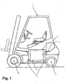
- the 1 shows a counterbalance forklift 1 with a so-called battery compartment 2.
- the battery compartment 2 is a battery 3 as an example of a replaceable power supply unit.
- the battery 3 can be removed from the vehicle 1, for example, by being lifted by another forklift and transported away laterally.
- the battery compartment 2 is arranged between the front axle 4 and the rear axle 5 and can be closed by means of a flap, not shown here.
- the battery compartment 2 is slightly larger than the outer dimensions of the largest power supply unit to be used, given the limited space in the forklift 1 but not larger than absolutely necessary.
- the battery 3 is therefore fixed in vehicles according to the prior art by means of operable by the operator holding devices, such as pivoting lever.
- the operator holding devices such as pivoting lever.
- a device 7 according to the invention for the automatic fixation of the battery 3 is arranged in the bottom 6 of the battery compartment 2.
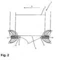
- the device 7 for fixing the battery 3 is shown in Figure 2 in a detailed view of the battery compartment 2, wherein a section along the vehicle longitudinal axis is shown.
- the device 7 consists of a plurality of latching hooks 8, which are arranged and guided in the bottom 6 of the battery compartment 2 and are pushed out by means of springs 9 upwards. If the battery 3 is discontinued, the locking hooks 8 located under the battery 3 are pressed into the bottom 6.
- the battery 3 is the first settling in a position in which a movement is possible, for example, because the battery 3 is placed exactly on the latching hook 8, that both edges 10 of the battery 3 to rest exactly on the tips of latching hooks 8 come, so in the first movement of the battery 3, for example during a start-up or braking, the battery 3 slip so far that on one side of the locking hooks 8 are released and the battery 3 can not perform any movement in the opposite direction.
- the simple mechanism shown can be selected.
- a device for removing the fixation may be advantageous. In the illustrated embodiment, this can be achieved by lowering the bottom plate 11, on which the springs 9 are supported.
- an unlocking mechanism can be actuated by an operator, or the lowering is coupled to the opening of the flap, not shown, with which the battery compartment 2 is closed while driving.
- latching hooks 8 are expediently arranged depending on the dimensions of the energy supply units used, that is to say, for example, as shown in FIG. 2, in rows which are oriented orthogonally to the vehicle longitudinal axis or also stepped.
- other locking elements are conceivable, such as, for example, pivotally mounted on one side plates, which are placed by means of spring force.
- torsion springs are also conceivable, which are particularly advantageous in pivotable locking elements.
Landscapes
- Engineering & Computer Science (AREA)
- Transportation (AREA)
- Structural Engineering (AREA)
- Mechanical Engineering (AREA)
- Life Sciences & Earth Sciences (AREA)
- Geology (AREA)
- Civil Engineering (AREA)
- Chemical & Material Sciences (AREA)
- Combustion & Propulsion (AREA)
- Forklifts And Lifting Vehicles (AREA)
- Arrangement Or Mounting Of Propulsion Units For Vehicles (AREA)
- Electric Propulsion And Braking For Vehicles (AREA)
- Vehicle Cleaning, Maintenance, Repair, Refitting, And Outriggers (AREA)
- Battery Mounting, Suspending (AREA)
Applications Claiming Priority (1)
| Application Number | Priority Date | Filing Date | Title |
|---|---|---|---|
| DE102006002243A DE102006002243A1 (de) | 2006-01-17 | 2006-01-17 | Flurförderzeug mit einer austauschbaren Energieversorgungseinheit |
Publications (2)
| Publication Number | Publication Date |
|---|---|
| EP1808403A2 true EP1808403A2 (fr) | 2007-07-18 |
| EP1808403A3 EP1808403A3 (fr) | 2008-10-08 |
Family
ID=37898340
Family Applications (1)
| Application Number | Title | Priority Date | Filing Date |
|---|---|---|---|
| EP06027087A Withdrawn EP1808403A3 (fr) | 2006-01-17 | 2006-12-29 | Chariot de manutention avec un bloc d'alimentation remplaçable |
Country Status (2)
| Country | Link |
|---|---|
| EP (1) | EP1808403A3 (fr) |
| DE (1) | DE102006002243A1 (fr) |
Cited By (3)
| Publication number | Priority date | Publication date | Assignee | Title |
|---|---|---|---|---|
| EP2298690A1 (fr) * | 2009-09-21 | 2011-03-23 | STILL GmbH | Système de changement de batterie d'un véhicule électrique |
| DE102019100454A1 (de) | 2018-12-31 | 2020-07-02 | Still Gmbh | Flurförderzeug |
| EP3677540A1 (fr) | 2018-12-31 | 2020-07-08 | STILL GmbH | Chariot de manutention |
Family Cites Families (4)
| Publication number | Priority date | Publication date | Assignee | Title |
|---|---|---|---|---|
| DE4105023C1 (fr) * | 1991-02-19 | 1992-07-16 | A. Raymond Kg, 7850 Loerrach, De | |
| DE9408233U1 (de) * | 1994-05-19 | 1994-07-14 | Gardena Kress + Kastner Gmbh, 89079 Ulm | Behälter oder Einsatz für Behälter |
| GB2411389B (en) * | 2003-11-10 | 2006-07-05 | Lansing Linde Ltd | Battery replacement system for an industrial truck |
| DE102005025647A1 (de) * | 2005-06-03 | 2006-12-07 | Still Gmbh | Flurförderzeug mit seitlich entnehmbarer Energieversorgungseinheit |
-
2006
- 2006-01-17 DE DE102006002243A patent/DE102006002243A1/de not_active Withdrawn
- 2006-12-29 EP EP06027087A patent/EP1808403A3/fr not_active Withdrawn
Cited By (4)
| Publication number | Priority date | Publication date | Assignee | Title |
|---|---|---|---|---|
| EP2298690A1 (fr) * | 2009-09-21 | 2011-03-23 | STILL GmbH | Système de changement de batterie d'un véhicule électrique |
| DE102010035818A1 (de) | 2009-09-21 | 2011-03-24 | Still Gmbh | Batteriewechselsystem eines Elektrofahrzeugs |
| DE102019100454A1 (de) | 2018-12-31 | 2020-07-02 | Still Gmbh | Flurförderzeug |
| EP3677540A1 (fr) | 2018-12-31 | 2020-07-08 | STILL GmbH | Chariot de manutention |
Also Published As
| Publication number | Publication date |
|---|---|
| EP1808403A3 (fr) | 2008-10-08 |
| DE102006002243A1 (de) | 2007-07-19 |
Similar Documents
| Publication | Publication Date | Title |
|---|---|---|
| DE202019001787U1 (de) | Abnehmbares Steckmodul für Materialhandhabungsfahrzeuge | |
| DE60006506T2 (de) | Kasten für elektrische akkumulatoreinheit | |
| DE102018121223A1 (de) | Vorrichtung zum Tragen mindestens einer Batterie für ein Kraftfahrzeug | |
| DE102017002249B4 (de) | Kraftfahrzeug und Fahrzeugkarosserie für ein Kraftfahrzeug | |
| DE102010035553A1 (de) | Flurförderzeug mit einem Batterieaufnahmeraum | |
| DE202015105053U1 (de) | Stapelbarer Behälter zur Ausbildung eines Behälterstapels aus gestapelten und insbesondere gekoppelten Behältern sowie Zubehör zum Bilden eines oberen Abschlusses des Behälterstapels | |
| DE102007061055B4 (de) | Klappenanordnung | |
| DE202019001786U1 (de) | Abnehmbares Steckmodul für Materialhandhabungsfahrzeuge | |
| DE102017117726A1 (de) | Gehäusevorrichtung für Energiespeichersysteme | |
| DE102004047339A1 (de) | Vorrichtung zur Verriegelung einer Batterie eines Hubwagens | |
| DE202008012144U1 (de) | Vorrichtung zur Sicherung einer Batterie in einem Batteriefach eines Flurförderzeugs | |
| DE102017121103A1 (de) | Flurförderzeug mit mehrteiligem Fahrzeugrahmen | |
| DE102021000361A1 (de) | Befestigungsanordnung für einen elektrischen Energiespeicher eines Fahrzeuges | |
| DE102019007961A1 (de) | Ladekabelverstauvorrichtung, Anordnung mit einer entsprechenden Ladekabelverstauvorrichtung und einer Hutablage, sowie elektrische betriebenes Fahrzeug mit einer entsprechenden Anordnung | |
| EP3293393A1 (fr) | Dispositif et procédé d'échange de composants échangeables d'une éolienne | |
| DE102018211346A1 (de) | Kraftfahrzeug | |
| DE102008034782A1 (de) | Flurförderzeug, insbesondere Gegengewichtsgabelstapler | |
| DE19622694B4 (de) | Flurförderzeug mit einem Batteriefach | |
| EP1686637B1 (fr) | Arrangement de plusieurs accumulateurs d'énergie dans un véhicule | |
| EP2534070A1 (fr) | Élément de préhension à encoches | |
| DE102009052371A1 (de) | Fahrzeug mit einem Energiespeicher | |
| DE102008060709A1 (de) | Energieversorgungseinheit, insbesondere Batterieblock, eines Flurförderzeugs | |
| EP1205424B1 (fr) | Chariot de manutention avec un bloc de batterie | |
| EP1808403A2 (fr) | Chariot de manutention avec un bloc d'alimentation remplaçable | |
| DE102017120241A1 (de) | Verfahren zur Montage und Demontage einer Telematikeinheit, Telematikeinheit und Baugruppe eines Fahrzeugs |
Legal Events
| Date | Code | Title | Description |
|---|---|---|---|
| PUAI | Public reference made under article 153(3) epc to a published international application that has entered the european phase |
Free format text: ORIGINAL CODE: 0009012 |
|
| AK | Designated contracting states |
Kind code of ref document: A2 Designated state(s): AT BE BG CH CY CZ DE DK EE ES FI FR GB GR HU IE IS IT LI LT LU LV MC NL PL PT RO SE SI SK TR |
|
| AX | Request for extension of the european patent |
Extension state: AL BA HR MK YU |
|
| PUAL | Search report despatched |
Free format text: ORIGINAL CODE: 0009013 |
|
| AK | Designated contracting states |
Kind code of ref document: A3 Designated state(s): AT BE BG CH CY CZ DE DK EE ES FI FR GB GR HU IE IS IT LI LT LU LV MC NL PL PT RO SE SI SK TR |
|
| AX | Request for extension of the european patent |
Extension state: AL BA HR MK RS |
|
| AKX | Designation fees paid | ||
| STAA | Information on the status of an ep patent application or granted ep patent |
Free format text: STATUS: THE APPLICATION IS DEEMED TO BE WITHDRAWN |
|
| 18D | Application deemed to be withdrawn |
Effective date: 20090409 |
|
| REG | Reference to a national code |
Ref country code: DE Ref legal event code: 8566 |