EP1808416A1 - Dispositif pour le traitement des eaux usées dans une petite station d'épuration - Google Patents
Dispositif pour le traitement des eaux usées dans une petite station d'épuration Download PDFInfo
- Publication number
- EP1808416A1 EP1808416A1 EP20060024634 EP06024634A EP1808416A1 EP 1808416 A1 EP1808416 A1 EP 1808416A1 EP 20060024634 EP20060024634 EP 20060024634 EP 06024634 A EP06024634 A EP 06024634A EP 1808416 A1 EP1808416 A1 EP 1808416A1
- Authority
- EP
- European Patent Office
- Prior art keywords
- disinfection unit
- clear water
- pump
- disinfection
- clarified water
- Prior art date
- Legal status (The legal status is an assumption and is not a legal conclusion. Google has not performed a legal analysis and makes no representation as to the accuracy of the status listed.)
- Withdrawn
Links
Images
Classifications
-
- C—CHEMISTRY; METALLURGY
- C02—TREATMENT OF WATER, WASTE WATER, SEWAGE, OR SLUDGE
- C02F—TREATMENT OF WATER, WASTE WATER, SEWAGE, OR SLUDGE
- C02F1/00—Treatment of water, waste water, or sewage
- C02F1/30—Treatment of water, waste water, or sewage by irradiation
- C02F1/32—Treatment of water, waste water, or sewage by irradiation with ultraviolet light
- C02F1/325—Irradiation devices or lamp constructions
-
- C—CHEMISTRY; METALLURGY
- C02—TREATMENT OF WATER, WASTE WATER, SEWAGE, OR SLUDGE
- C02F—TREATMENT OF WATER, WASTE WATER, SEWAGE, OR SLUDGE
- C02F3/00—Biological treatment of water, waste water, or sewage
- C02F3/02—Aerobic processes
- C02F3/12—Activated sludge processes
- C02F3/1236—Particular type of activated sludge installations
- C02F3/1242—Small compact installations for use in homes, apartment blocks, hotels or the like
-
- C—CHEMISTRY; METALLURGY
- C02—TREATMENT OF WATER, WASTE WATER, SEWAGE, OR SLUDGE
- C02F—TREATMENT OF WATER, WASTE WATER, SEWAGE, OR SLUDGE
- C02F2201/00—Apparatus for treatment of water, waste water or sewage
- C02F2201/32—Details relating to UV-irradiation devices
- C02F2201/326—Lamp control systems
-
- C—CHEMISTRY; METALLURGY
- C02—TREATMENT OF WATER, WASTE WATER, SEWAGE, OR SLUDGE
- C02F—TREATMENT OF WATER, WASTE WATER, SEWAGE, OR SLUDGE
- C02F2209/00—Controlling or monitoring parameters in water treatment
- C02F2209/40—Liquid flow rate
-
- Y—GENERAL TAGGING OF NEW TECHNOLOGICAL DEVELOPMENTS; GENERAL TAGGING OF CROSS-SECTIONAL TECHNOLOGIES SPANNING OVER SEVERAL SECTIONS OF THE IPC; TECHNICAL SUBJECTS COVERED BY FORMER USPC CROSS-REFERENCE ART COLLECTIONS [XRACs] AND DIGESTS
- Y02—TECHNOLOGIES OR APPLICATIONS FOR MITIGATION OR ADAPTATION AGAINST CLIMATE CHANGE
- Y02W—CLIMATE CHANGE MITIGATION TECHNOLOGIES RELATED TO WASTEWATER TREATMENT OR WASTE MANAGEMENT
- Y02W10/00—Technologies for wastewater treatment
- Y02W10/10—Biological treatment of water, waste water, or sewage
Definitions
- the present invention relates to a device for treating waste water in a small sewage treatment plant according to the preamble of claim 1.
- Small wastewater treatment plants such as those in the DE 199 07 980 C2 as well as in the EP 00 103 417 are shown, include a primary clarifier, optionally a buffer tank and a treatment tank in which the actual biological wastewater treatment takes place.
- This arrangement can be summarized to a three-chamber tank, in which within a single container, the basins are formed by separate chambers, which are separated by partitions.
- the term "small sewage treatment plant” is used in a broader sense and does not refer exclusively to plants of the type described above, but to smaller wastewater treatment plants in general.
- the clarification in the treatment tank is made by a device comprising different units with different functions.
- One of these units is a clear water removal pump for discharging the clarified water from the small sewage treatment plant.
- the discharged clear water is either directed into an above-ground receiving water or seeped underground.
- the other units may be an aerator, a level gauge, a mud pump or the like.
- Object of the present invention is therefore to provide a device of the type mentioned above, which allows an improvement in the hygienic quality of the clarified water with relatively simple, straightforward and cost-effective means.
- the device according to the invention comprises, as a further unit, a UV disinfection unit which serves for the disinfection of the clear water evacuated by the clear water removal pump by ultraviolet light.
- a UV disinfection unit which serves for the disinfection of the clear water evacuated by the clear water removal pump by ultraviolet light.
- the UV disinfection unit is arranged in the drain line of the clear water removal pump.
- the units of the device according to the invention including the clear water removal pump and the UV disinfection unit are arranged in a common housing.
- the device comprises a control device for controlling the intensity of the radiation of the light source of the UV disinfection unit and / or the flow time of the clear water through the UV disinfection unit.
- the UV disinfection unit is preferably operated with ultraviolet light having a wavelength of 254 nm.
- Claim 6 relates to a method for operating the device according to the invention, while claim 7 relates to a particular embodiment of this method.
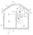
- the single figure shows a schematic cross section through a preferred embodiment of the device according to the invention.
- reference numeral 10 denotes a container having a circular outline, which comprises a bottom 12, a cylindrical side wall 14 and a conical head 16.
- the container 10 may consist entirely of concrete.
- the side wall 14 is usually composed of ring segments and the individual segments are stacked on the ground 12, while the head piece 16 is placed on the uppermost ring segment.
- the head piece 16 comprises at its upper end a circular opening 18 which can be closed by a lid.
- the interior of the container 10 is divided by a vertical partition 20 into a primary clarifier 22 and a treatment tank 24.
- dirty water first enters the primary clarifier 22 and can rest there for a certain period of time, so that sludge can settle on the bottom of the primary sedimentation tank 22.
- the pre-clarified water can be pumped by a pump, not shown, in the treatment tank 24, in which the actual biological wastewater treatment takes place.
- three-chamber containers are often used, which in addition to a primary clarifier and a treatment basin further comprise a buffer tank, in which the pre-clarified water from the primary clarifier 22 is first introduced before it is pumped further into the treatment tank 24. Since this is irrelevant to the operation of the present invention, a simplified variant is shown in the figure, which includes only the primary clarifier 22.
- a wastewater treatment apparatus 30 comprising a plurality of aggregates.
- a Tauchbelclarer 32 which enters the necessary for aerobic clarification oxygen in the wastewater. This oxygen is taken up by microorganisms which are present in the activated sludge contained in the treatment tank 24 and convert the pollutants of the waste water into biomass.
- This ventilation through the submersible aerator 32 occurs periodically. In settling phases between the aeration periods, the water in the treatment chamber 24 is kept at rest, so that the sludge components can sink to the bottom and forms a clear water phase near the surface. This clear water near the surface is therefore already biologically precleared.
- a clear water removal pump 34 as a further unit of the device 30 is immersed in the clear water phase in the treatment tank 24 so that they can pump the clear water via a drain line 36 into an opening provided in the wall 14 of the container 10 drain 38, through which it flows to the outside can.
- the clear water removal pump 34 is operated at intervals during the settling phases, in which forms a calm clear water phase.
- a UV disinfection unit 40 is arranged as a further unit, which serves to disinfect the clear water discharged by the clear water removal pump 34 by means of ultraviolet light, so that the clear water that reaches the outlet 38 and is discharged to the environment , is germ-free.
- the UV disinfection unit for this purpose comprises an ultraviolet light source disposed within a conduit so that the water flowing through the conduit is exposed to intense ultraviolet radiation.
- the intensity and wavelength of this radiation should be such that the microorganisms contained in the water are killed as effectively as possible.
- a wavelength of 254 nm has proved to be particularly effective.
- the disinfection performance can be controlled by a suitable dimensioning of the flow time of the clear water flowing through the UV disinfection device 40. The longer the flow time, the longer the UV light can act on the microorganisms contained in the water.
- the intensity of the radiation is suitable to choose.
- the treatment parameters ie in particular the flow time through the UV disinfection unit and the intensity, can be controlled by a control unit not shown in the figure. This can also be used to synchronize the operating intervals of the UV disinfection unit 40 with those of the clear water removal pump 34 such that the UV disinfection unit 40 is operated during the operation of the clear water removal pump 34. Further, the UV disinfection unit 40 may be turned on earlier than the clear water take-off pump 34 and later terminate its operation so that the operating interval of the pump 34 falls within the longer operating interval of the UV disinfection unit 40. A mode of operation has proved to be particularly effective in which an operating interval of the UV disinfection unit 40 begins 5 minutes before the start of an operating interval of the clear water removal pump 34 and ends 5 minutes after the end of an operating interval of the clear water removal pump 34.
- the aggregates of the device 30 may be housed in a common housing so that the device 30 forms a module that can be removably mounted in the housing 10, for example, by hanging on the partition wall 20. It is understood that it is further possible only a part of the aggregates in a housing summarize, so in particular the clear water removal pump 34 and the UV disinfection unit 40th
Landscapes
- Life Sciences & Earth Sciences (AREA)
- Hydrology & Water Resources (AREA)
- Engineering & Computer Science (AREA)
- Environmental & Geological Engineering (AREA)
- Water Supply & Treatment (AREA)
- Chemical & Material Sciences (AREA)
- Organic Chemistry (AREA)
- Health & Medical Sciences (AREA)
- Toxicology (AREA)
- Biodiversity & Conservation Biology (AREA)
- Microbiology (AREA)
- Physical Water Treatments (AREA)
Applications Claiming Priority (1)
| Application Number | Priority Date | Filing Date | Title |
|---|---|---|---|
| DE10601635 | 2006-01-11 |
Publications (1)
| Publication Number | Publication Date |
|---|---|
| EP1808416A1 true EP1808416A1 (fr) | 2007-07-18 |
Family
ID=37806845
Family Applications (1)
| Application Number | Title | Priority Date | Filing Date |
|---|---|---|---|
| EP20060024634 Withdrawn EP1808416A1 (fr) | 2006-01-11 | 2006-11-28 | Dispositif pour le traitement des eaux usées dans une petite station d'épuration |
Country Status (1)
| Country | Link |
|---|---|
| EP (1) | EP1808416A1 (fr) |
Cited By (1)
| Publication number | Priority date | Publication date | Assignee | Title |
|---|---|---|---|---|
| DE102008004663A1 (de) | 2008-01-11 | 2009-07-16 | Bergmann Clean Abwassertechnik Gmbh | Verfahren zur elektrochemischen Hygienisierung und Keimminderung von biologisch gereinigtem Abwasser, insbesondere häuslichem Abwasser und von Abwasserteilströmen und Vorrichtung dazu |
Citations (6)
| Publication number | Priority date | Publication date | Assignee | Title |
|---|---|---|---|---|
| US3950249A (en) * | 1974-01-23 | 1976-04-13 | Thetford Corporation | Sanitary waste treatment plant |
| US5254246A (en) * | 1991-07-16 | 1993-10-19 | Sonia Rivelli | Water reclamation system |
| WO1999067173A2 (fr) * | 1998-06-12 | 1999-12-29 | Jordforsk | Installation de filtrage d'eaux usees |
| US6358411B1 (en) * | 2000-05-19 | 2002-03-19 | Mckinney Jerry L. | Wastewater treatment plant |
| EP1245538A1 (fr) * | 2001-03-27 | 2002-10-02 | Evac International Oy | Dispositif d'épuration des eaux usées |
| DE102005055593A1 (de) | 2005-11-19 | 2007-05-24 | Reinhard Boller | Verfahren und Vorrichtung zur Entkeimung von Abwasser in Kleinkläranlagen und kleinen Kläranlagen sowie sonstigen technischen Anlagen mittels einer einfachen Vorrichtung |
-
2006
- 2006-11-28 EP EP20060024634 patent/EP1808416A1/fr not_active Withdrawn
Patent Citations (6)
| Publication number | Priority date | Publication date | Assignee | Title |
|---|---|---|---|---|
| US3950249A (en) * | 1974-01-23 | 1976-04-13 | Thetford Corporation | Sanitary waste treatment plant |
| US5254246A (en) * | 1991-07-16 | 1993-10-19 | Sonia Rivelli | Water reclamation system |
| WO1999067173A2 (fr) * | 1998-06-12 | 1999-12-29 | Jordforsk | Installation de filtrage d'eaux usees |
| US6358411B1 (en) * | 2000-05-19 | 2002-03-19 | Mckinney Jerry L. | Wastewater treatment plant |
| EP1245538A1 (fr) * | 2001-03-27 | 2002-10-02 | Evac International Oy | Dispositif d'épuration des eaux usées |
| DE102005055593A1 (de) | 2005-11-19 | 2007-05-24 | Reinhard Boller | Verfahren und Vorrichtung zur Entkeimung von Abwasser in Kleinkläranlagen und kleinen Kläranlagen sowie sonstigen technischen Anlagen mittels einer einfachen Vorrichtung |
Non-Patent Citations (1)
| Title |
|---|
| IVERY G: "Aerobic treatment units (ATUs): Appropriate technology for on-site wastewater treatment and re-use", DESALINATION, ELSEVIER, AMSTERDAM, NL, vol. 106, no. 1, August 1996 (1996-08-01), pages 295 - 303, XP004019177, ISSN: 0011-9164 * |
Cited By (1)
| Publication number | Priority date | Publication date | Assignee | Title |
|---|---|---|---|---|
| DE102008004663A1 (de) | 2008-01-11 | 2009-07-16 | Bergmann Clean Abwassertechnik Gmbh | Verfahren zur elektrochemischen Hygienisierung und Keimminderung von biologisch gereinigtem Abwasser, insbesondere häuslichem Abwasser und von Abwasserteilströmen und Vorrichtung dazu |
Similar Documents
| Publication | Publication Date | Title |
|---|---|---|
| EP1531123B1 (fr) | Méthode et installation pour traiter des eaux de déchet de bateaux | |
| EP2165021A2 (fr) | Dispositif et procédé d'épuration des eaux ménagères | |
| EP1919833B1 (fr) | Dispositif d'epuration des eaux usees | |
| EP0851844A1 (fr) | Procede d'epuration des eaux usees | |
| EP2157056A1 (fr) | Procédé et dispositif destinés à la préparation d'eau grise | |
| EP0893413A1 (fr) | Procédé et dispositif pour le traitement biologique de liquides, en particulier pour la complète clarification de l'eau usée | |
| DE20020795U1 (de) | Vorrichtung zum Behandeln von Abwasser | |
| DE19807890C2 (de) | Verfahren und Kleinkläranlage zum Behandeln von Schwarz und/oder Grauwasser mit Membrantechnologie | |
| EP1808416A1 (fr) | Dispositif pour le traitement des eaux usées dans une petite station d'épuration | |
| DE102006001635A1 (de) | Vorrichtung zur Behandlung von Abwasser in einer Kleinkläranlage | |
| WO2007045007A1 (fr) | Appareil et procede pour le traitement des eaux d'egout | |
| WO2013134264A1 (fr) | Système et procédé de traitement de l'eau | |
| DE19538387A1 (de) | Verfahren und Vorrichtung zur Umrüstung einer Mehrkammer-Kleinkläranlage | |
| EP1388524A1 (fr) | Procédé discontinu de traitement des eaux usées et petite installation pour sa mise en oeuvre | |
| DE10039984A1 (de) | Verfahren zur Reinigung von Abwasser und Kläranlage zur Durchführung des Verfahrens | |
| RU2698694C1 (ru) | Способ аэробной биологической очистки сточных вод взвешенным активным илом с гидроавтоматическим режимом регулирования скорости рециркуляции в зависимости от единовременных объемов неравномерно подаваемых сточных вод частных домов и специальным ночным режимом денитрификации и устройство для его осуществления | |
| EP1338566B1 (fr) | Dispositif pour la purification des eaux usées par la méthode des boues activées | |
| EP1723084A2 (fr) | Installation et procede de traitement de matieres fecales et unite membrane | |
| EP1369386A2 (fr) | Dispositif d'aération d'eaux usées et de nettoyage d'une installation à membranes et microstation d'épuration d'eau contenant ce dispositif | |
| DE20316374U1 (de) | Kläreinrichtung | |
| DE10002910A1 (de) | Verfahren und Einrichtung zum Entfernen von gereinigtem Abwasser aus Kläranlagen mit Aufstaubetrieb, insbesondere aus SBR-Reaktoren | |
| AT403374B (de) | Kompakte kleinkläranlage | |
| DE102004019962A1 (de) | Transportable Kleinkläranlage zum Behandeln von Schwarz- und/oder Grauwasser, häuslichem Abwasser sowie häuslichem Abwasser in seiner Zusammensetzung ähnlichem Abwasser | |
| DE29915706U1 (de) | Einrichtung zur biologischen Abwasserbehandlung | |
| DE102006052965A1 (de) | Verfahren zur Klärung von Abwasser in einer Kleinkläranlage sowie eine Kleinkläranlage |
Legal Events
| Date | Code | Title | Description |
|---|---|---|---|
| PUAI | Public reference made under article 153(3) epc to a published international application that has entered the european phase |
Free format text: ORIGINAL CODE: 0009012 |
|
| AK | Designated contracting states |
Kind code of ref document: A1 Designated state(s): AT BE BG CH CY CZ DE DK EE ES FI FR GB GR HU IE IS IT LI LT LU LV MC NL PL PT RO SE SI SK TR |
|
| AX | Request for extension of the european patent |
Extension state: AL BA HR MK YU |
|
| 17P | Request for examination filed |
Effective date: 20070810 |
|
| 17Q | First examination report despatched |
Effective date: 20071113 |
|
| AKX | Designation fees paid |
Designated state(s): AT BE BG CH CY CZ DE DK EE ES FI FR GB GR HU IE IS IT LI LT LU LV MC NL PL PT RO SE SI SK TR |
|
| GRAP | Despatch of communication of intention to grant a patent |
Free format text: ORIGINAL CODE: EPIDOSNIGR1 |
|
| STAA | Information on the status of an ep patent application or granted ep patent |
Free format text: STATUS: THE APPLICATION IS DEEMED TO BE WITHDRAWN |
|
| 18D | Application deemed to be withdrawn |
Effective date: 20090603 |
|
| TPAC | Observations filed by third parties |
Free format text: ORIGINAL CODE: EPIDOSNTIPA |