EP1808417A1 - Appareil et procédé de fabrication de corps en verre utilisant un système de distribution par aérosol - Google Patents
Appareil et procédé de fabrication de corps en verre utilisant un système de distribution par aérosol Download PDFInfo
- Publication number
- EP1808417A1 EP1808417A1 EP06026230A EP06026230A EP1808417A1 EP 1808417 A1 EP1808417 A1 EP 1808417A1 EP 06026230 A EP06026230 A EP 06026230A EP 06026230 A EP06026230 A EP 06026230A EP 1808417 A1 EP1808417 A1 EP 1808417A1
- Authority
- EP
- European Patent Office
- Prior art keywords
- aerosol
- precursor
- lvp
- vapor
- particles
- Prior art date
- Legal status (The legal status is an assumption and is not a legal conclusion. Google has not performed a legal analysis and makes no representation as to the accuracy of the status listed.)
- Granted
Links
Images


Classifications
-
- C—CHEMISTRY; METALLURGY
- C03—GLASS; MINERAL OR SLAG WOOL
- C03B—MANUFACTURE, SHAPING, OR SUPPLEMENTARY PROCESSES
- C03B19/00—Other methods of shaping glass
- C03B19/14—Other methods of shaping glass by gas- or vapour- phase reaction processes
- C03B19/1415—Reactant delivery systems
- C03B19/1438—Reactant delivery systems for delivering and depositing additional reactants as liquids or solutions, e.g. solution doping of the article or deposit
-
- B—PERFORMING OPERATIONS; TRANSPORTING
- B01—PHYSICAL OR CHEMICAL PROCESSES OR APPARATUS IN GENERAL
- B01D—SEPARATION
- B01D1/00—Evaporating
- B01D1/0005—Evaporating devices suitable for floating on water
-
- C—CHEMISTRY; METALLURGY
- C03—GLASS; MINERAL OR SLAG WOOL
- C03B—MANUFACTURE, SHAPING, OR SUPPLEMENTARY PROCESSES
- C03B37/00—Manufacture or treatment of flakes, fibres, or filaments from softened glass, minerals, or slags
- C03B37/01—Manufacture of glass fibres or filaments
- C03B37/012—Manufacture of preforms for drawing fibres or filaments
- C03B37/014—Manufacture of preforms for drawing fibres or filaments made entirely or partially by chemical means, e.g. vapour phase deposition of bulk porous glass either by outside vapour deposition [OVD], or by outside vapour phase oxidation [OVPO] or by vapour axial deposition [VAD]
- C03B37/01413—Reactant delivery systems
- C03B37/01433—Reactant delivery systems for delivering and depositing additional reactants as liquids or solutions, e.g. for solution doping of the porous glass preform
-
- C—CHEMISTRY; METALLURGY
- C03—GLASS; MINERAL OR SLAG WOOL
- C03B—MANUFACTURE, SHAPING, OR SUPPLEMENTARY PROCESSES
- C03B37/00—Manufacture or treatment of flakes, fibres, or filaments from softened glass, minerals, or slags
- C03B37/01—Manufacture of glass fibres or filaments
- C03B37/012—Manufacture of preforms for drawing fibres or filaments
- C03B37/014—Manufacture of preforms for drawing fibres or filaments made entirely or partially by chemical means, e.g. vapour phase deposition of bulk porous glass either by outside vapour deposition [OVD], or by outside vapour phase oxidation [OVPO] or by vapour axial deposition [VAD]
- C03B37/018—Manufacture of preforms for drawing fibres or filaments made entirely or partially by chemical means, e.g. vapour phase deposition of bulk porous glass either by outside vapour deposition [OVD], or by outside vapour phase oxidation [OVPO] or by vapour axial deposition [VAD] by glass deposition on a glass substrate, e.g. by inside-, modified-, plasma- or plasma modified- chemical vapour deposition [ICVD, MCVD, PCVD, PMCVD], i.e. by thin layer coating on the inside or outside of a glass tube or on a glass rod
- C03B37/01807—Reactant delivery systems, e.g. reactant deposition burners
- C03B37/01838—Reactant delivery systems, e.g. reactant deposition burners for delivering and depositing additional reactants as liquids or solutions, e.g. for solution doping of the deposited glass
-
- C—CHEMISTRY; METALLURGY
- C03—GLASS; MINERAL OR SLAG WOOL
- C03B—MANUFACTURE, SHAPING, OR SUPPLEMENTARY PROCESSES
- C03B2201/00—Type of glass produced
- C03B2201/06—Doped silica-based glasses
- C03B2201/20—Doped silica-based glasses doped with non-metals other than boron or fluorine
- C03B2201/28—Doped silica-based glasses doped with non-metals other than boron or fluorine doped with phosphorus
-
- C—CHEMISTRY; METALLURGY
- C03—GLASS; MINERAL OR SLAG WOOL
- C03B—MANUFACTURE, SHAPING, OR SUPPLEMENTARY PROCESSES
- C03B2201/00—Type of glass produced
- C03B2201/06—Doped silica-based glasses
- C03B2201/30—Doped silica-based glasses doped with metals, e.g. Ga, Sn, Sb, Pb or Bi
- C03B2201/31—Doped silica-based glasses doped with metals, e.g. Ga, Sn, Sb, Pb or Bi doped with germanium
-
- C—CHEMISTRY; METALLURGY
- C03—GLASS; MINERAL OR SLAG WOOL
- C03B—MANUFACTURE, SHAPING, OR SUPPLEMENTARY PROCESSES
- C03B2201/00—Type of glass produced
- C03B2201/06—Doped silica-based glasses
- C03B2201/30—Doped silica-based glasses doped with metals, e.g. Ga, Sn, Sb, Pb or Bi
- C03B2201/34—Doped silica-based glasses doped with metals, e.g. Ga, Sn, Sb, Pb or Bi doped with rare earth metals, i.e. with Sc, Y or lanthanides, e.g. for laser-amplifiers
-
- C—CHEMISTRY; METALLURGY
- C03—GLASS; MINERAL OR SLAG WOOL
- C03B—MANUFACTURE, SHAPING, OR SUPPLEMENTARY PROCESSES
- C03B2201/00—Type of glass produced
- C03B2201/06—Doped silica-based glasses
- C03B2201/30—Doped silica-based glasses doped with metals, e.g. Ga, Sn, Sb, Pb or Bi
- C03B2201/34—Doped silica-based glasses doped with metals, e.g. Ga, Sn, Sb, Pb or Bi doped with rare earth metals, i.e. with Sc, Y or lanthanides, e.g. for laser-amplifiers
- C03B2201/36—Doped silica-based glasses doped with metals, e.g. Ga, Sn, Sb, Pb or Bi doped with rare earth metals, i.e. with Sc, Y or lanthanides, e.g. for laser-amplifiers doped with rare earth metals and aluminium, e.g. Er-Al co-doped
-
- C—CHEMISTRY; METALLURGY
- C03—GLASS; MINERAL OR SLAG WOOL
- C03B—MANUFACTURE, SHAPING, OR SUPPLEMENTARY PROCESSES
- C03B2207/00—Glass deposition burners
- C03B2207/80—Feeding the burner or the burner-heated deposition site
- C03B2207/81—Constructional details of the feed line, e.g. heating, insulation, material, manifolds, filters
-
- C—CHEMISTRY; METALLURGY
- C03—GLASS; MINERAL OR SLAG WOOL
- C03B—MANUFACTURE, SHAPING, OR SUPPLEMENTARY PROCESSES
- C03B2207/00—Glass deposition burners
- C03B2207/80—Feeding the burner or the burner-heated deposition site
- C03B2207/85—Feeding the burner or the burner-heated deposition site with vapour generated from liquid glass precursors, e.g. directly by heating the liquid
- C03B2207/87—Controlling the temperature
Definitions
- This invention relates to glass bodies (e.g., optical fibers, planar waveguides, glass soot) and, more particularly, to apparatus and methods for fabricating rare-earth (RE)-doped optical fibers.
- glass bodies e.g., optical fibers, planar waveguides, glass soot
- RE rare-earth
- preforms are made by flowing relatively high vapor pressure (HVP) precursor gasses (e.g., SiCl 4 , GeCl 4 and POCl 3 ) and oxygen down a rotating silica substrate tube.
- HVP vapor pressure
- An external hydrogen-oxygen torch slowly traverses the length of the tube, locally heating a small section of the tube.
- the gas stream which moves much faster than the torch, is heated as it approaches the torched section and becomes hot enough that the precursors react with the oxygen and form oxide aerosol particles. These particles grow in size by colliding and coalescing with one another. As the gas stream leaves the torched section, it remains hot relative to the tube wall.
- This temperature gradient between the tube and gas stream causes the aerosol particles to move towards and deposit onto the tube wall, forming a soot layer.
- the soot sinters into a solid glass layer.
- the process is iterated to deposit multiple glass layers on the inside wall of the tube; for example, hundreds of layers may be deposited to fabricate the core of a conventional silica fiber, but many fewer (e.g., 3-15) are typically deposited to fabricate the core of a RE-doped fiber.
- the tube is heated and collapsed to form a solid rod known as a preform.
- Optical fiber is drawn from the preform using standard techniques.
- HVP precursors do not exist.
- An appropriate precursor needs to have a relatively high vapor pressure (above ⁇ 1 torr at room temperature) and should not contain any chemicals (e.g., hydrogen, water) that will adversely affect the properties of the deposited glass.
- Some desirable dopants such as RE elements [particularly erbium (Er) and ytterbium (Yb)] have low vapor pressure (LVP) precursors and cannot be delivered using conventional vapor-phase approaches, such as standard MCVD.
- a soot layer is deposited on the inside wall of a substrate tube using standard dopants, but the soot layer is not sintered.
- the soot layer is soaked with a liquid solution containing a LVP RE precursor. When the solution is drained out of the tube, the soot layer acts like a sponge holding a certain amount of the solution in the pores of the soot.
- the soot layer containing the LVP precursor is dried, the LVP precursor is oxidized, and the soot layer is sintered.
- Solution doping has the following limitations: (i) The reproducibility of the LVP dopant concentration is poor from preform to preform; (ii) The amount of liquid held by the soot layer is dependent on its porosity, which is very difficult to control; and (iii) The process is very time consuming typically taking 1-2 hours per deposited glass layer compared to roughly 10 minutes for a standard MCVD glass layer.
- Chelates Preforms have been fabricated using chelate precursors of RE elements. Chelates are large organo-metallic compounds that have relatively high vapor pressures. Chelate processes have the following limitation: The chelates contain undesirable elements such as hydrogen and to date have not produced glass with the purity needed for high quality optical fibers.
- An ampoule containing the desired LVP RE precursor is placed inside an MCVD substrate tube.
- the ampoule is heated with an external source (such as a flame or furnace) to a temperature high enough to obtain the necessary vapor pressure.
- an external source such as a flame or furnace
- the ampoule approach has the following limitations: (i) The precursor vapor pressure (and therefore the amount delivered) is very sensitive to temperature, which is difficult to control because an external heat source heats the RE source material, which sits within several concentric glass tubes; (ii) Flowing gas streams cool the tubes, causing uncertainty in the actual source temperature; (iii) Only a small surface area exists between the precursor and the carrier gas, so it is unlikely that the precursor will become saturated in the carrier gas. This leads to variations in the amount of precursor delivered if the surface changes either in size or gets coated by, for example, a RE oxide layer; and (iv) When the precursor leaves the ampoule, some or all of the precursor reacts with the surrounding oxygen to form metal oxide aerosol particles. The size of these aerosol particles is not controlled. If large particles are formed, current wisdom suggests that they will form clusters, which may be detrimental for RE-doped preforms and fibers.
- Liquid Aerosol Delivery A solution, which contains organo-metallic precursors for all the desired dopants in an organic solvent, is nebulized into a liquid aerosol (droplets) and delivered into the substrate tube. As the liquid aerosol approaches the hot zone, the solvent evaporates and the resulting solid aerosol particles oxidize and deposit onto the substrate tube as a layer of soot. Care is taken not to sinter the soot layer. The soot layer goes through several processing (purification) steps to remove undesirable elements such as hydrogen (H) and carbon (C). Finally the soot layer is sintered. See, for example, two papers by T. F. Morse, et al., J. Non-Crystal. Solids, Vol. 129, pp.
- This liquid aerosol approach has the following limitations: (i) The solution is flammable and can lead to explosions; (ii) A new solution needs to be made whenever a different glass composition is desired; (iii) The process is time consuming; and (iv) The process is not expected to produce very low loss glass inasmuch as the reaction products include contaminants such as H 2 O and H 2 as well as the desired glass oxides.
- a method of fabricating a glass body e.g., an optical waveguide, a planar waveguide, or glass soot
- a glass body e.g., an optical waveguide, a planar waveguide, or glass soot
- a first dopant e.g., a RE element
- the method comprises the steps of: (a) generating a first single-component aerosol (SCA) from the LVP precursor; that is, each first aerosol particle includes only the LVP precursor of the first dopant; (b) separately generating vapors of the other constituents; generating steps (a) and (b) taking place at a location remote from the deposition system used to form the glass body; (c) convecting the aerosol of step (a) and the vapors of step (b) from the remote location through a conduit system to the deposition system, which includes a substrate; and (d) forming at least one doped layer on a surface of the substrate.
- SCA single-component aerosol
- our method includes the additional step of separately generating a second SCA from the second LVP precursor; that is, each second aerosol particle also includes only the LVP precursor of the second dopant.
- the two aerosols may be maintained separate from one another while being convected to the deposition system. Alternatively, they may be mixed with one another and/or the vapors of the other constituents, and the mixture may then be convected to the deposition system.
- a method of fabricating a glass body that includes a multiplicity of constituents, at least one constituent being a first dopant having a first LVP precursor comprising the steps of: (a) generating a first aerosol comprising first particles that include the first LVP precursor, the generating step including the steps of (a1) providing a vapor of the LVP precursor and (a2) supersaturating the LVP vapor to form the aerosol; (b) separately generating vapors of the other constituents; (c) convecting the aerosol of step (a) and the vapors of step (b) to a deposition system including a substrate; and (d) forming on a surface of the substrate at least one doped layer comprising the dopants contained in the aerosol and vapors convected in step (c).
- the aerosol generator comprises a vessel having first and second chambers coupled in fluid-flow communication with one another.
- the first chamber is a bubbler chamber and the second chamber is a condenser chamber.
- a heater surrounds the first chamber, keeping it at an essentially constant temperature.
- a first input port enables primary carrier gas to be fed into the bubbler chamber, and a second input port enables cooler, secondary carrier gas to be fed into the condenser chamber.
- An output port is coupled to the condenser chamber.
- the precursor typically a solid at room temperature
- the precursor is placed in the bubbler chamber, which is heated to a relatively high temperature sufficient to liquefy the precursor and to obtain a desired vapor pressure of me precursor.
- the primary carrier gas convects the precursor vapor away from the precursor liquid and into the condenser chamber. (Preferably, the precursor vapor fully saturates the primary carrier gas.) Since the precursor vapor cannot be delivered at such high temperatures (i.e., it would condense on the walls of standard tubing used to deliver the vapor to the deposition system), it is quickly cooled by the cooler, secondary carrier gas fed into the second input port. Consequently, an aerosol of the precursor is formed in the condenser chamber and is extracted via the output port.
- the aerosol can be delivered at or slightly above room temperature through standard tubing without significant agglomeration or deposition, which enables the aerosol to be convected into a standard deposition system along with standard vapor species.
- the first chamber is a reaction chamber.
- a sub-precursor is placed in the first chamber, and the primary gas is a gas that reacts with the sub-precursor to generate a precursor compound in vapor form.
- This vapor is convected into the condenser chamber, a cooler secondary carrier gas is flowed into the condenser chamber, and an aerosol is formed in the manner described above.
- Our delivery system may be used in conjunction with a variety of glass deposition systems, such as MCVD, OVD and VAD.
- the glass bodies may take the form of glass soot layers that are deposited on a surface of a heated substrate and then sintered to form glass layers. Such glass layers may be used to from optical fibers, for example.
- the glass bodies formed by our invention may take the form of glass soot that is not intentionally deposited on a heated substrate and sintered; rather it is flowed to a suitable collector (e.g., the soot is collected on the surface of a vacuum bag, which serves as an unheated substrate). Such soot may be easily removed from the collector and then used, for example, in sol-gel processes for making optical fibers.
- the glass body includes at least one dopant that has a LVP precursor.
- Such dopants include RE-elements (e.g., Er, Yb, Nd, Tm, Ho and La, or a combination of them) as well as aluminum (Al) and alkaline earth elements (e.g., Be, Mg and Ca).
- RE-elements e.g., Er, Yb, Nd, Tm, Ho and La, or a combination of them
- Al aluminum
- alkaline earth elements e.g., Be, Mg and Ca
- our invention is applicable to the fabrication of optical fibers by MCVD, which entails depositing soot glass layers on the inside surface of a heated substrate tube, sintering the layers, collapsing the tube into a preform, and drawing optical fibers from the preform. It is also applicable to the fabrication of optical fibers fabricated by VAD and OVD, which entail depositing soot glass layers onto the outside or end surface of a rotating cylinder, sintering the soot layers, and drawing optical fibers from the preform. On the other hand, our invention is also applicable to the fabrication of planar optical waveguides, which entails depositing glass layers on a major surface of a planar substrate. For simplicity and for purposes of illustration only, however, the following description will focus on the fabrication of optical fibers using heated substrate tubes.
- an aerosol we mean a particle-gas combination in which solid or liquid LVP precursor particles are suspended in a carrier gas.
- Each particle includes a multiplicity (typically thousands) of molecules of the LVP precursor.
- an aerosol may be a single-component aerosol (SCA) or a multi-component aerosol (MCA).
- SCA single-component aerosol
- MCA multi-component aerosol
- each particle includes molecules of only a single LVP precursor. Even when two or more aerosols are mixed, the particles maintain their separate identities; that is, each particle includes molecules of only a single precursor.
- each particle comprises at least two compounds that include precursors of the dopants or host material and/or oxides of the dopants or host materials.
- apparatus 10 for fabricating an optical fiber includes a multiplicity of precursor sources 12, which generate precursors of the various constituents (e.g., host material such as silica, LVP dopants identified above, and standard HVP dopants such as Ge and P) of the optical fiber.
- the sources 12 include at least one aerosol generator 12a, which provides a SCA of a LVP precursor (e.g., a RE chloride).
- the sources 12 include at least one conventional vapor generator (or bubbler) 12b, 12c, 12d, which provides vapors of other fiber constituents, typically those that have HVP precursors (e.g., chlorides of Si, Ge and PO).
- HVP precursors e.g., chlorides of Si, Ge and PO
- the sources 12 are located remote from glass-layer deposition system 16. Illustratively, they are coupled in parallel fluid-flow communication with one another but in series fluid-flow communication with deposition system 16.
- system 16 could be, for example, an MCVD system, an OVD system, a VAD system, or any other deposition system compatible with our precursor delivery system. For purposes of illustration only, the description that follows will assume that deposition system 16 is a standard MCVD system.
- MCVD system 16 typically includes a feedstock tube 16.1, a substrate tube 16.2, and an exhaust tube 16.3 arranged in tandem with one another.
- the feedstock, substrate and exhaust tubes are rotated (arrow 16.4) about their common longitudinal axis, and a heat source (i.e., a torch) 16.5 is translated (arrow 16.6) along that axis to heat the substrate tube.
- the vapor and aerosol precursors enter the feedstock tube 16.1 via a standard rotary union (not shown). This union allows the feedstock tube to rotate on the MCVD lathe while the delivery tubing 18 remains stationary.
- the aerosol precursor can be delivered into system 16 using the same port as the vapor precursors, or it can be delivered via a separate port. We have found it convenient to deliver the aerosol precursor using its own port.
- conduit system e.g., tubing 18
- the aerosol and vapor precursors After being delivered to the MCVD feedstock tube 16.1, the aerosol and vapor precursors are oxidized in the hot zone of the substrate tube 16.2, the oxides form a soot that deposits onto the inside of the substrate tube 16.2, the deposited soot is sintered, the substrate tube is collapsed into a preform, and the preform is drawn into an optical fiber.
- the multiplicity of sources 12 includes one for each of the constituents of the optical fiber to be formed.
- the aerosol generator 12a provides a SCA of the RE precursor (e.g., a RE-chloride such as ErCl 3 or YbCl 3 )
- vapor generator 12b provides a vapor of a silica precursor (e.g., SiCl 4 )
- vapor generator 12c provides a vapor of a Ge precursor (e.g., GeCl 4 )
- vapor generator 12d provides a vapor of a P precursor (e.g., POCl 3 ).
- the carrier gas used for the sources 12 should be inert (e.g., He, Ar,), beneficial to the production of high quality glass (e.g., O 2 ), or useful for other processing reasons that do not adversely affect the fiber (e.g., N 2 , Cl 2 ).
- He is typically used since it helps minimize bubble formation during sintering.
- O 2 is typically used in the generators (bubblers) 12b, 12c, 12d. (Since the bubblers are maintained at relatively low temperatures (e.g., ⁇ 100 °C), the metal chloride precursors do not oxidize in the bubbler.)
- additional sources of carrier gases e.g., He, O 2
- additional sources of dopant gases that are vapors at room temperature (e.g., SiF 4 ) and hence do not require bubblers to generate the requisite vapor pressure.
- the aerosol generators 12a, 12a' enable us to deliver LVP dopants (e.g., RE dopants) at low temperatures to the MCVD system and at concentrations high enough to maintain standard deposition rates.
- LVP dopants e.g., RE dopants
- Each source 12 heats the precursor to a temperature well above room temperature in order to generate the precursor gases at the desired vapor pressure.
- the precursor is typically heated to 30-50 °C (e.g., 38 °C).
- dopants derived from LVP precursors e.g., RE dopants such as Er and Yb
- the situation is much more severe - they are typically heated to 800-1100 °C (e.g., 900 °C for the precursor ErCl 3 ; 950 °C for YbCl 3 ).
- tubing 18, which couples the generators to the MCVD system 16 is typically maintained at a much lower temperature (e.g., 50 -100 °C; by heaters well-known, but not shown) than the LVP dopant source in the generator 12a, such hot gases cannot be delivered via the significantly lower temperature tubing to the MCVD system because the hot LVP precursor gases would condense and deposit onto the inner wall of the tubing.
- Our solution to this problem is to generate the LVP fiber constituents as aerosols that can be delivered to the MCVD system 16 via tubing 18 maintained at or slightly above room temperature.
- the tubing 18 should be maintained at a temperature (e.g., 70 °C) higher than the temperature (e.g., 38 °C) of the hottest bubbler 12b, 12c, 12d if the aerosol is mixed with the HVP vapors, as shown in FIG. 1.
- a temperature e.g., 70 °C
- 38 °C the temperature of the hottest bubbler 12b, 12c, 12d
- all of the tubing connected to the output of an aerosol generator e.g., 12a
- an aerosol generator e.g., 12a
- Conditions are set at the aerosol generator to produce particles having a predetermined (e.g., optimum or near optimum) size range, enabling the desired LVP dopant concentration to be delivered to the headstock tube with little loss.
- a predetermined size range e.g., optimum or near optimum
- Conditions in the hot zone can then be set (e.g., optimized or nearly optimized independent of any aerosol generator conditions) so that all the dopants react together to form an essentially homogeneous glass.
- the aerosol particles should be oxidized before reaching the hot zone.
- the LVP oxide particles can then be filtered before being delivered so only the optimal cluster size is formed in the glass.
- the cluster size is determined in this case by the delivered dopant oxide because the particles do not vaporize (change size) in the hot zone.
- the size of the aerosol particles is preferably in the approximate range of 0.01 ⁇ m to 1.0 ⁇ m.
- particles as large as 10 ⁇ m can be delivered, if needed, provided care is taken to minimize the distance between the aerosol generator and the substrate tube. If the particles are significantly larger than 1 ⁇ m, they will settle on the inside wall of the delivery tubing due to gravity. If they are significantly smaller than 0.01 ⁇ m, they will deposit on the tubing wall due to Brownian motion. In one embodiment of our invention, we remove large particles during delivery, which is extremely advantageous because in most cases large particles produce clusters in RE-doped fibers, and clusters are known to cause undesirable processes such as up-conversion.
- RE-aerosol particles may be inherently removed in the tubing 18 or in other components of the delivery system (e.g., the condensation chamber 12.1 discussed later), this type of particle filtering is not readily controlled. Therefore, in accordance with one embodiment of our invention, these particles are passed through filters 14, which are interposed between aerosol generators 12a, 12a' and deposition system 16.
- the filters may include a well-known diffusion battery to remove small particles (e.g., those below 0.01 ⁇ m).
- the filters 14 may include a well-known cyclone, or a piece of tubing with several bends (e.g., a coil), or a settling chamber, depending on how efficiently the user desires to remove larger particles.
- the collection efficiency of a coil of tubing for a given particle size is a function of the tubing's inside diameter, number of loops in the coil, flow rate, and the gas and particle properties. For example, consider YbCl 3 particles in He flowing through four tubes having inside diameters of 1.5, 2, 3 and 4 mm, each tube having two and half loops. For 1.0 ⁇ m particles the collection efficiency of the different diameter coils is about 92%, 65%, 27% and 12%, respectively; for 1.4 ⁇ m particles the corresponding efficiency is about 99%, 84%, 48%, and 26%, respectively; and for 2.0 ⁇ m particles the corresponding efficiency is about 100%, 100%, 72%, and 42%, respectively.
- the smaller diameter tubing (1.5 mm and 2 mm) collects nearly all of the particles with sizes above about 2 ⁇ m, whereas the larger diameter tubing (3 mm and 4 mm) does not collect nearly all of the particles until the particle size reaches about 4 ⁇ m (3 mm tubing) and greater than 5 ⁇ m (4 mm tubing).
- the larger diameter tubing (3 mm and 4 mm) does not collect nearly all of the particles until the particle size reaches about 4 ⁇ m (3 mm tubing) and greater than 5 ⁇ m (4 mm tubing).
- Aerosol particle size is commonly controlled by the particle collision and coalescence times, which are discussed more fully below in conjunction with the description of aerosol generator 12a of FIG. 2.
- feedback subsystem 30 includes a sensor 30.1 that senses the size and/or number of particles generated by aerosol generator 12a.
- a monitor 30.2 processes the signal generated by sensor 30.1 and transmits a control (e.g., error) signal to a controller 30.3, which in turn transmits one or more control signals on output bus 30.4.
- the latter control signals control components of the delivery system that alter the size and number of aerosol particles.
- Such components include mass flow controllers that control the flow rate of various gases and/or heaters that control the temperature(s) of the aerosol generator 12a.
- Monitor 30.2 might include, for example, a commercially available particle sizer spectrometer (not shown).
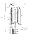
- aerosol generator 12a, 12a' comprises a vessel 12.1 a first chamber 12.2 and a second chamber 12.3 coupled in fluid-flow communication with one another.
- the first chamber is a bubbler chamber 12.2 located in a first (e.g., lower) portion
- the second chamber is a condenser chamber 12.3 located in a second (e.g., upper) portion.
- a bulb-like region 12.8 is coupled to the bottom of the bubbler chamber 12.2.
- a first heater 12.4a surrounds the lower portion; i.e., both the bubbler chamber 12.2 and bulb-like region 12.8.
- a first input port 12.5 enables primary carrier gas (e.g., He) to be fed into the bulb-like region 12.8 via tube 22, and a second input port 12.6 enables cooler secondary carrier gas (e.g., room temperature He) to be piped into the condenser chamber 12.3 via tube 24.
- primary carrier gas e.g., He
- cooler secondary carrier gas e.g., room temperature He
- a second heater surrounds all (or a significant fraction) of the condenser chamber 12.3.
- the second heater 12.4b maintains the condenser chamber 12.3 at a lower temperature than the bubbler chamber 12.2 in order to minimize condensation on the glass wall and to produce the desired aerosol particle size(s).
- An output tube 26 is coupled to the condenser chamber 12.3 via output port 12.7.
- bubbler chamber 12.2 and condenser chamber 12.3 are located in lower and upper portions, respectively, of generator 12a, it will be apparent to those skilled in the art that the two chambers may be located in other positions (e.g., side by side).
- the bulb-like region 12.8 is filled with a high purity LVP precursor solid 12.9 (e.g., a 6-9's pure RE-chloride available from commercial sources), which is heated to a relatively high temperature (e.g., 800-1100 °C) sufficient to liquefy the precursor and to obtain a desired vapor pressure.
- a relatively high temperature e.g., 800-1100 °C
- the primary carrier gas bubbles through the liquefied precursor, entraining the precursor vapor away from the precursor liquid (hot region) and into the condenser chamber 12.3 (cooler region).
- the precursor vapor fully saturates the primary carrier gas in the bulb like region 12.8.
- the condenser chamber 12.3 which is maintained at a significantly lower temperature (e.g., 500 °C)
- the precursor vapor is supersaturated. Consequently, a RE aerosol 12.0 forms in the condenser chamber 12.3 and exits the vessel via the output port 12.7.
- the latter port is coupled in fluid-flow communication with the MCVD system 16 via output tube 26 and delivery tubing 18 (FIG. 1), which are maintained at or slightly above room temperature.
- tubing 18 should be heated to a temperature (e.g., 70 °C) slightly higher that of the highest temperature HVP bubbler (e.g., 38 °C for SiCl 4 bubbler 12b in the embodiment of FIG. 1) to keep the HVP precursor from condensing on the tubing during delivery.
- HVP bubbler e.g., 38 °C for SiCl 4 bubbler 12b in the embodiment of FIG. 1
- the aerosol can be delivered either at room temperature or at this slightly higher temperature. Once the aerosol reaches the hot zone of the MCVD system where deposition on the substrate tube 16.2 is to take place, it is vaporized and converted to an oxide, as discussed previously.
- the first chamber 12.2 is a reaction chamber.
- a sub-precursor e.g., Al metal
- the primary gas is a gas (e.g., Cl 2 ) that reacts with the sub-precursor to generate a precursor compound (e.g., Al 2 Cl 6 ) in vapor form.
- a precursor compound e.g., Al 2 Cl 6
- This vapor is convected into the condenser chamber, a cooler secondary carrier gas (e.g., He) is flowed into the condenser chamber, and an aerosol is formed in the manner described above.
- a cooler secondary carrier gas e.g., He
- the vapor convected into the second (condenser) chamber 12.3 includes at least one chemical element derived from the LVP substance (precursor or sub-precursor), that element ultimately becoming a dopant in the glass body formed.
- the coupling between precursor sources 12 and the MCVD system 16 is illustratively controlled by means of three-way valves 13a-d.
- Each valve has an off, vent and run position. As shown, the valves are in the vent position, which enables the generators to run continuously and to deliver the precursor to the MCVD system 16 only when needed. This feature reduces start up fluctuations.
- preselected valves are rotated to their run positions, which places the corresponding selected sources 12 in fluid-flow communication with system 16.
- aerosol particle size is commonly determined by the particle collision and coalescence times. Collision time, which varies with volume loading (aerosol volume per carrier gas volume) is controlled by the temperature of heater 12.4a (i.e., the temperature of the RE chloride 12.9), the flow rate of primary carrier gas into tube 22 and flow rate of dilution gas into tube 24. On the other hand, the coalescence time is controlled by the temperature of heater 12.4b (i.e., the temperature of condenser chamber 12.3), the fraction of the condenser chamber not surrounded by heater 12.4b, the shape of the condenser chamber exit port 12.7, the flow rate of the dilution gas into tube 24, and the temperature of the dilution gas.
- heater 12.4a i.e., the temperature of the RE chloride 12.9
- the coalescence time is controlled by the temperature of heater 12.4b (i.e., the temperature of condenser chamber 12.3), the fraction of the condenser chamber not surrounded by heater 12.4b, the shape of
- Our system has a number of important features and advantages: (1) The ability to utilize high purity precursors, such as metal chlorides, obviates the need for additional purification steps; (2) The size and design of our aerosol generators enables them to produce essentially the same mass output for relatively long periods of time (e.g., the long residence time of the carrier gas bubbles in contact with the precursor and the ability to generate small bubbles (large surface-to-volume ratio) insures that the precursor vapor reaches equilibrium with the carrier gas.
- the generators can easily be designed to need refilling only after several hundred hours of use, which makes the set up time between MCVD preforms as quick as that for preforms made with only HVP dopants; and (3) Our aerosol generators are independent of other parts of the system.
- Aerosol generator 12a contains the precursor YbCl 3 .
- the amount of YbCl 3 and the shape of the generator enable the YbCl 3 to reach its equilibrium vapor pressure when the primary He flow via tube 22 is flowed (bubbled) through it.
- the generator's standard operating temperature is 950 °C but can be purposely raised or lowered (e.g., 800 °C - 1100 °C) when higher or lower aerosol volume loadings are desired.
- Primary He flow via tube 22 flows to the bottom of the bulb-like region 12.8 where it bubbles through the liquefied YbCl 3 12.9.
- the total flow bubbler and dilution
- Standard flow is about 0.5 liter/min for each of the He flows. Typical ranges are about 0.2-1 liters /min, but higher or lower flow rates can be used.
- the temperature of heaters 12.4a, 12.4b and the flow rates of the He carrier gasses are set before the run starts to insure that the system is running at equilibrium conditions.
- the aerosol is sent to the vent instead of the system 16 using three-way valve 13a.
- the MCVD system 16 is set up and operated in standard fashion. Assuming non-Yb doped glass layers are desired in, for example, the fiber cladding, these layers are fabricated by closing valve 13a but otherwise using standard MCVD techniques. Illustratively, Yb doping is present only in the fiber core, and the Yb distribution is essentially radially uniform. At the end of the last cladding layer, valve 13a is switched on so that the YbCl 3 aerosol flows into the delivery tubing. The aerosol flows to the rotating seal along with all the other selected vapor dopants; e.g., SiCl 4 and GeCl 4 are selected by switching on valves 13b and 13c and switching off valve 13d.
- Yb doping is present only in the fiber core, and the Yb distribution is essentially radially uniform.
- valve 13a is switched on so that the YbCl 3 aerosol flows into the delivery tubing.
- the aerosol flows to the rotating seal along with all the other selected vapor dop
- the soot is formed, deposited, and sintered on the inside wall of the substrate tube 16.2 using standard MCVD methods and temperatures. There is no need for extra purification passes.
- all the aerosol and vapor dopants flows are turned off using individual three-way valves 13a to 13d.
- the pressure in the substrate tube 16.2 is lowered, and the tube 16.2 is collapsed into a preform using standard MCVD techniques.
- the preform is then drawn into suitable lengths of optical fiber, again using standard fiber drawing techniques.
- core passes translations of heat source 16.6 along substrate tube 16.2 are made in order to deposit correspondingly five or more RE-doped core layers. More than five, or fewer than five, layers may be deposited, of course.
- Suitable tubing includes 3/8-inch outside diameter Teflon tubing 18 to deliver the aerosol and vapors from the generators 12 to the rotating seal.
- a suitable settling chamber (as optional filter 14) to filter out the large YbCl 3 particles comprises a 3-inch inside diameter tube, which slows down the flow sufficiently that large particles settled out of the carrier gas stream due to gravity.
- our method does not employ any organic compounds (e.g., solvents or precursors) and, as such, is also free of undesirable contaminants (e.g., H 2 O and other hydrogen-containing species) that are by-products of the use of such compounds in the prior art.
- organic compounds e.g., solvents or precursors
- undesirable contaminants e.g., H 2 O and other hydrogen-containing species
- the LVP aerosol particles and carrier gas are free of organic compounds. Consequently, our process does not require any additional purification steps to remove such contaminants.
- YbCl 3 was the LVP precursor of Yb, and Yb was used as a dopant in the silica fiber. (Yb was actually incorporated in the fiber as an oxide, but it was the Yb element that altered the gain properties of the doped silica, as is well known in the art.) A settling chamber was used as a filter 14.
- Example 1 The first example outlines a Yb-Al-doped silica preform that we fabricated.
- the YbCl 3 aerosol generator 12a was maintained at 975 °C to achieve a high concentration of Yb.
- the primary He flow that bubbled through the molten YbCl 3 was set to 0.5 liters/min, and the secondary He flow that cooled the saturated YbCl 3 vapor in the condenser chamber 12.1 was set to 0.3 liters/min. These conditions for the aerosol generator were maintained for 1 hr before delivery to allow the system to reach equilibrium.
- the MCVD system 16 was set up in the usual fashion, and all steps prior to the deposition of the Yb-Al-doped silica soot layers were carried out with the aerosol three-way valve 13a set to vent and using standard MCVD techniques.
- the valve 13a was switched so that the aerosol entered the delivery tube and mixed with the other precursor and process gases (e.g., He, O 2 ).
- the SiCl 4 bubbler 12b was maintained at 38 °C. 100 sccm of O 2 was bubbled through the SiCl 4 precursor.
- Al 2 Cl 6 vapor was used as a precursor for Al (incorporated as an oxide in silica) and was flowed directly into the substrate tube 16.2 at a rate of 6.7 sccm.
- 900 sccm of O 2 and 400 sccm of He were flowed to assist in oxidation and sintering, respectively.
- the precursors were oxidized by traversing the H 2 /O 2 torch 16.5 across the substrate tube 16.2 to heat the outside surface of the tube to 2100 °C.
- a suitable number of cladding layers were first deposited. Then, after eight Yb-Al-doped core layers were deposited, the valve 13a was returned to the vent position, the pressure in the substrate tube was reduced, and the substrate tube containing the deposited layers was collapsed into a rod in the usual fashion.
- the difference in refractive index between the Yb-Al-doped region and the undoped region of this preform was 0.007 and the Yb concentration was approximately 1.6 wt%.
- the eight layers produced a cross sectional area of 7 mm 2 .
- Example 2 The second example outlines the fabrication of another Yb-Al-doped silica preform, as well as a fiber we drew from it.
- the aerosol generator 12a was maintained at 950 °C.
- the primary He flow that bubbled through the molten YbCl 3 was set to 0.38 liters/min and the secondary He flow that cooled the saturated YbCl 3 vapor in the condenser chamber 12.1 was set to 0.5 liters/min. These conditions for the aerosol generator were maintained for 1 hr before delivery to allow the system to reach equilibrium.
- the MCVD system 16 was set up in the usual fashion and all steps prior to the deposition of the Yb-Al-doped silica were carried out with the aerosol three-way valve 13a set to vent using standard MCVD techniques.
- the valve 13a was switched so that the aerosol entered the delivery tube and mixed with the other precursor and process gases.
- the SiCl 4 bubbler 12b was maintained at 38 °C. 100 sccm of O 2 was bubbled through the SiCl 4 precursor.
- Al 2 Cl 6 vapor was used as a precursor for Al and was flowed directly into the substrate tube 16.2 at a rate of 5 sccm.
- precursors 900 sccm of O 2 and 200 sccm of He were flowed to assist in oxidation and sintering, respectively.
- the precursors were oxidized by traversing a H 2 /O 2 torch across the substrate tube 16.2 to heat the outside surface of the tube to 2000 °C.
- a suitable number of cladding layers were first deposited. Then, after eight Yb-Al-doped core layers were deposited, the valve 13a was returned to the vent position, the pressure in the substrate tube was reduced, and the substrate tube containing the deposited layers was collapsed into a rod in the usual fashion.
- the difference in refractive index between the Yb-Al-doped region and the undoped region of this preform was 0.006 and the Yb concentration was approximately 0.8 wt%.
- the eight layers produced a cross sectional area of 7 mm 2 .
- This preform was then jacketed with a silica tube and drawn into a fiber to obtain the correct core/clad geometry to sustain single-transverse-mode operation at a pump wavelength of 975 nm.
- FIG. 3 compares two cases: Curve I - a commercially available Yb-doped fiber that is advertised and sold as a low-photodarkening fiber, and Curve II - a Yb-doped fiber that was fabricated using a standard MCVD system in which the YbCl 3 -precursor was delivered as a SCA, in accordance with one embodiment of our invention.
- a SCA there are many ways to form a SCA.
- chemical reactions can also be used to form an aerosol. For example, as discussed earlier, reacting a RE chloride with oxygen at a temperature at which the RE chloride is a vapor (e.g., at 950 °C).
- a sub-precursor such as aluminum (Al) can be reacted with Cl 2 to produce Al 2 Cl 6 vapor (e.g., at 350 °C), which can then be cooled to form an aerosol.
- Al aluminum
- the aerosol 12.0 flows in tube 16.7 that is concentrically positioned within the feedstock tube 16.1. Near its end the inner tube 16.7 is heated by means of an external heat source 16.9. The aerosol 12.0 will vaporize and then be flowed as a vapor into the preform tube 16.2 (FIG. 1). Oxygen is flowed in the feedstock tube 16.1 to oxidize the aerosol and vapors delivered by the delivery system of FIG. 1. Alternatively, the oxygen may be flowed in the inner tube 16.7 and the aerosol may be flowed in the feedstock tube 16.1. (The primary purpose of the inner tube is to keep the aerosol and oxygen separated so that the aerosol is not oxidized prematurely; i.e., before it is vaporized.)
- This method may be desirable if the aerosol particles are made larger for higher mass loadings or if the aerosol particles agglomerate too much due to long delivery residence times (notwithstanding filtering) and the fiber starts to show signs of undesirable rare earth clustering.
- the particles either vaporize as they approach the MCVD system's hot zone forming the ideal (LVP vapor mixed with HVP vapors) or they oxidize before vaporizing.
- the size of the delivered particles is important in terms of delivery efficiency but not in terms of the fiber's optical properties if they vaporize completely before oxidizing. There is some indication that this is what happens with YbCl 3 .
- the RE-chloride particles may oxidize first, in which case their size will influence the size of the oxide particles and therefore their size is important and needs to be as small as possible.
- an optional oxidizer may be interposed between each of the aerosol generators 12a, 12a' and the deposition system 16.
- the oxidizer may be a separate oxidizing chamber 20, as shown in FIG. 1, or it may simply be the upper chamber 12.3 of generator 12a (with O 2 flow into via tube 24 and He flow into tube 22).
- oxides have an extremely low vapor pressure, which means that the oxide particles will not vaporize in the hot zone of the substrate tube, leading to less homogeneity in the deposited glass layers.
- each aerosol particle comprises at least two compounds that include precursors (e.g., chlorides) of the dopants or host material and/or oxides of the dopants or host materials.
- a MCA could comprise particles each of which is a composite of two (or more) RE dopant precursors, such as YbCl 3 and ErCl 3 .
- a MCA could comprise particles each of which is a composite of a RE dopant precursor and a non-RE LVP dopant, such as YbCl 3 and Al 2 O 3 (alumina), respectively.
- a MCA could comprise particles each of which is a composite of a RE dopant precursor (e.g., YbCl 3 ) and an oxide of a HVP dopant (e.g., Ge 2 O 3 ) and/or an oxide of host material (e.g., SiO 2 ).
- a RE dopant precursor e.g., YbCl 3
- an oxide of a HVP dopant e.g., Ge 2 O 3
- an oxide of host material e.g., SiO 2
- a MCA aerosol can be generated, for example, by using the generator 12a of FIG. 2.
- the cooler secondary carrier gas of generator 12a may include suitable seed particles to seed condensation of a RE vapor.
- the seed particles may themselves be generated by another, separate generator.
- seed particles may be LVP precursors or oxides, such as RE chlorides or alumina; or they may be HVP oxides, such as SiO 2 or Ge 2 O 3 , or a combination of them; i.e., a multi-component seed aerosol.
- the seed particles are preferably a homogeneous composition of each of the aerosol's constituents, which is advantageous in the production of homogeneous glass bodies, particular optical fibers.
- a method of fabricating a glass body that includes a multiplicity of constituents, at least one constituent being a first dopant having a first LVP precursor comprising the steps of: (a) generating a first aerosol comprising first particles that include the first LVP precursor, the generating step including the steps of (a1) providing a vapor of the LVP precursor and (a2) supersaturating the LVP vapor to form the aerosol; (b) separately generating vapors of the other constituents; (c) convecting the aerosol of step (a) and the vapors of step (b) to a deposition system including a substrate; and (d) forming on a surface of the substrate at least one doped layer comprising the dopants contained in the aerosol and vapors convected in step (c).
- the aerosol may be either a MCA or a SCA.
- This method may be practiced using the apparatus previously described in conjunction with FIGs. 1-2.
Landscapes
- Chemical & Material Sciences (AREA)
- Engineering & Computer Science (AREA)
- Chemical Kinetics & Catalysis (AREA)
- Manufacturing & Machinery (AREA)
- Materials Engineering (AREA)
- Organic Chemistry (AREA)
- General Chemical & Material Sciences (AREA)
- Life Sciences & Earth Sciences (AREA)
- General Life Sciences & Earth Sciences (AREA)
- Geochemistry & Mineralogy (AREA)
- Manufacture, Treatment Of Glass Fibers (AREA)
Priority Applications (1)
| Application Number | Priority Date | Filing Date | Title |
|---|---|---|---|
| EP14169465.3A EP2772470B1 (fr) | 2005-12-16 | 2006-12-18 | Système de distribution par aérosol |
Applications Claiming Priority (2)
| Application Number | Priority Date | Filing Date | Title |
|---|---|---|---|
| US75096605P | 2005-12-16 | 2005-12-16 | |
| US11/634,002 US8069690B2 (en) | 2005-12-16 | 2006-12-05 | Apparatus and method for fabricating glass bodies using an aerosol delivery system |
Related Child Applications (3)
| Application Number | Title | Priority Date | Filing Date |
|---|---|---|---|
| EP14169465.3A Division EP2772470B1 (fr) | 2005-12-16 | 2006-12-18 | Système de distribution par aérosol |
| EP14169465.3A Previously-Filed-Application EP2772470B1 (fr) | 2005-12-16 | 2006-12-18 | Système de distribution par aérosol |
| EP14169465.3A Division-Into EP2772470B1 (fr) | 2005-12-16 | 2006-12-18 | Système de distribution par aérosol |
Publications (2)
| Publication Number | Publication Date |
|---|---|
| EP1808417A1 true EP1808417A1 (fr) | 2007-07-18 |
| EP1808417B1 EP1808417B1 (fr) | 2019-02-27 |
Family
ID=37896002
Family Applications (2)
| Application Number | Title | Priority Date | Filing Date |
|---|---|---|---|
| EP14169465.3A Ceased EP2772470B1 (fr) | 2005-12-16 | 2006-12-18 | Système de distribution par aérosol |
| EP06026230.0A Active EP1808417B1 (fr) | 2005-12-16 | 2006-12-18 | Procédé de fabrication de corps en verre utilisant un système de distribution par aérosol |
Family Applications Before (1)
| Application Number | Title | Priority Date | Filing Date |
|---|---|---|---|
| EP14169465.3A Ceased EP2772470B1 (fr) | 2005-12-16 | 2006-12-18 | Système de distribution par aérosol |
Country Status (3)
| Country | Link |
|---|---|
| US (2) | US8069690B2 (fr) |
| EP (2) | EP2772470B1 (fr) |
| JP (1) | JP4891750B2 (fr) |
Families Citing this family (38)
| Publication number | Priority date | Publication date | Assignee | Title |
|---|---|---|---|---|
| US8749054B2 (en) | 2010-06-24 | 2014-06-10 | L. Pierre de Rochemont | Semiconductor carrier with vertical power FET module |
| JP4843611B2 (ja) | 2004-10-01 | 2011-12-21 | デ,ロシェモント,エル.,ピエール | セラミックアンテナモジュール及びその製造方法 |
| CN101213638B (zh) | 2005-06-30 | 2011-07-06 | L·皮尔·德罗什蒙 | 电子元件及制造方法 |
| US8354294B2 (en) | 2006-01-24 | 2013-01-15 | De Rochemont L Pierre | Liquid chemical deposition apparatus and process and products therefrom |
| US7959598B2 (en) | 2008-08-20 | 2011-06-14 | Asante Solutions, Inc. | Infusion pump systems and methods |
| US8952858B2 (en) | 2009-06-17 | 2015-02-10 | L. Pierre de Rochemont | Frequency-selective dipole antennas |
| US8922347B1 (en) | 2009-06-17 | 2014-12-30 | L. Pierre de Rochemont | R.F. energy collection circuit for wireless devices |
| US8552708B2 (en) | 2010-06-02 | 2013-10-08 | L. Pierre de Rochemont | Monolithic DC/DC power management module with surface FET |
| US9023493B2 (en) | 2010-07-13 | 2015-05-05 | L. Pierre de Rochemont | Chemically complex ablative max-phase material and method of manufacture |
| CN103415925A (zh) | 2010-11-03 | 2013-11-27 | L·皮尔·德罗什蒙 | 具有单片集成的量子点器件的半导体芯片载体及其制造方法 |
| JP2012254888A (ja) * | 2011-06-07 | 2012-12-27 | Sumitomo Electric Ind Ltd | 光ファイバ母材製造装置および光ファイバ母材製造方法 |
| EP3001834B1 (fr) * | 2013-05-03 | 2018-03-07 | Council of Scientific & Industrial Research | Procédé de fabrication d'une fibre optique dopée à l'ytterbium |
| US9561324B2 (en) | 2013-07-19 | 2017-02-07 | Bigfoot Biomedical, Inc. | Infusion pump system and method |
| WO2017123525A1 (fr) | 2016-01-13 | 2017-07-20 | Bigfoot Biomedical, Inc. | Interface utilisateur pour système de gestion du diabète |
| US10806859B2 (en) | 2016-01-14 | 2020-10-20 | Bigfoot Biomedical, Inc. | Adjusting insulin delivery rates |
| HK1256995A1 (zh) | 2016-01-14 | 2019-10-11 | Bigfoot Biomedical, Inc. | 药物输送设备、系统和方法中的阻塞解决方案 |
| US12383166B2 (en) | 2016-05-23 | 2025-08-12 | Insulet Corporation | Insulin delivery system and methods with risk-based set points |
| US10363374B2 (en) | 2016-05-26 | 2019-07-30 | Insulet Corporation | Multi-dose drug delivery device |
| US11096624B2 (en) | 2016-12-12 | 2021-08-24 | Bigfoot Biomedical, Inc. | Alarms and alerts for medication delivery devices and systems |
| US11033682B2 (en) | 2017-01-13 | 2021-06-15 | Bigfoot Biomedical, Inc. | Insulin delivery methods, systems and devices |
| EP3568860B1 (fr) | 2017-01-13 | 2025-12-10 | Insulet Corporation | Méthodes, systèmes et dispositifs d'administration d'insuline |
| US10583250B2 (en) | 2017-01-13 | 2020-03-10 | Bigfoot Biomedical, Inc. | System and method for adjusting insulin delivery |
| US10881792B2 (en) | 2017-01-13 | 2021-01-05 | Bigfoot Biomedical, Inc. | System and method for adjusting insulin delivery |
| US10758675B2 (en) | 2017-01-13 | 2020-09-01 | Bigfoot Biomedical, Inc. | System and method for adjusting insulin delivery |
| US10500334B2 (en) | 2017-01-13 | 2019-12-10 | Bigfoot Biomedical, Inc. | System and method for adjusting insulin delivery |
| GB201703383D0 (en) | 2017-03-02 | 2017-04-19 | Gargle Tech Ltd | Testing for particulates |
| USD874471S1 (en) | 2017-06-08 | 2020-02-04 | Insulet Corporation | Display screen with a graphical user interface |
| USD928199S1 (en) | 2018-04-02 | 2021-08-17 | Bigfoot Biomedical, Inc. | Medication delivery device with icons |
| US12562251B1 (en) | 2018-05-09 | 2026-02-24 | Bigfoot Biomedical, Inc. | Computing architecture for assuring the provenance of medication therapy related parameters, and related systems, methods and devices |
| EP3846939B1 (fr) | 2018-09-05 | 2023-05-03 | Hero Scientific Ltd | Détection de particules |
| USD920343S1 (en) | 2019-01-09 | 2021-05-25 | Bigfoot Biomedical, Inc. | Display screen or portion thereof with graphical user interface associated with insulin delivery |
| EP4118412A1 (fr) | 2020-03-11 | 2023-01-18 | Hero Scientific Ltd | Dispositifs de test |
| USD977502S1 (en) | 2020-06-09 | 2023-02-07 | Insulet Corporation | Display screen with graphical user interface |
| CA3201894A1 (fr) | 2020-12-18 | 2022-06-23 | Matthew Alles | Association d'un dispositif d'administration de medicament a une montre intelligente et a un systeme d'info-divertissement de vehicule |
| CA3202405A1 (fr) | 2021-01-06 | 2022-07-14 | Zvi Feldman | Dispositifs d'echantillonnage a filtration |
| US12514980B2 (en) | 2021-06-30 | 2026-01-06 | Insulet Corporation | Adjustment of medicament delivery by a medicament delivery device based on menstrual cycle phase |
| US12521486B2 (en) | 2021-07-16 | 2026-01-13 | Insulet Corporation | Method for modification of insulin delivery during pregnancy in automatic insulin delivery systems |
| EP4646726A1 (fr) | 2023-01-06 | 2025-11-12 | Insulet Corporation | Administration de bolus de repas lancée automatiquement ou manuellement avec assouplissement automatique ultérieur des contraintes de sécurité |
Citations (7)
| Publication number | Priority date | Publication date | Assignee | Title |
|---|---|---|---|---|
| US4574078A (en) | 1983-02-25 | 1986-03-04 | Montedison S.P.A. | Process and apparatus for preparing monodispersed, spherical, non-agglomerated metal oxide particles having a size below one micron |
| JPH03119305A (ja) | 1989-10-03 | 1991-05-21 | Nippon Telegr & Teleph Corp <Ntt> | 光導波膜の製造方法 |
| US5622750A (en) * | 1994-10-31 | 1997-04-22 | Lucent Technologies Inc. | Aerosol process for the manufacture of planar waveguides |
| WO1999006331A1 (fr) * | 1997-07-30 | 1999-02-11 | Corning Incorporated | Procede d'obtention de silice par combustion de reactifs liquides, a l'aide d'oxygene |
| WO2000026151A1 (fr) * | 1998-10-30 | 2000-05-11 | Corning Incorporated | Procedes de fabrication de suie pour preformes de fibres optiques et preformes produites par ces procedes |
| US20020157423A1 (en) | 2001-04-30 | 2002-10-31 | Intelcore Technologies, Inc. | Hybrid manufacturing process for optical fibers |
| EP1752423A2 (fr) * | 1998-10-05 | 2007-02-14 | Liekki OY | Procédé de pulvérisation des grains de verre |
Family Cites Families (20)
| Publication number | Priority date | Publication date | Assignee | Title |
|---|---|---|---|---|
| US69638A (en) * | 1867-10-08 | Jesse davis | ||
| US1952A (en) * | 1841-01-27 | Method of constructing corn-shellers where a disk is used by adapting | ||
| US3883336A (en) * | 1974-01-11 | 1975-05-13 | Corning Glass Works | Method of producing glass in a flame |
| CA1166527A (fr) * | 1979-09-26 | 1984-05-01 | Shiro Takahashi | Methode et dispositif pour la production d'une preforme de fibre de verre multicomposante |
| US4661140A (en) * | 1985-02-06 | 1987-04-28 | Sumitomo Electric Industries, Ltd. | Gas reaction apparatus and multi-wall pipe type burner therefor |
| US4666247A (en) * | 1985-02-08 | 1987-05-19 | American Telephone And Telegraph Company, At&T Bell Laboratories | Multiconstituent optical fiber |
| US4801411A (en) * | 1986-06-05 | 1989-01-31 | Southwest Research Institute | Method and apparatus for producing monosize ceramic particles |
| JPH0781965A (ja) * | 1993-07-22 | 1995-03-28 | Sumitomo Electric Ind Ltd | ガス生成装置並びに光導波路及び光ファイバ母材を製造する方法及び装置 |
| KR100342189B1 (ko) * | 1995-07-12 | 2002-11-30 | 삼성전자 주식회사 | 휘발성복합체를사용한희토류원소첨가광섬유제조방법 |
| US6849334B2 (en) * | 2001-08-17 | 2005-02-01 | Neophotonics Corporation | Optical materials and optical devices |
| US7384680B2 (en) * | 1997-07-21 | 2008-06-10 | Nanogram Corporation | Nanoparticle-based power coatings and corresponding structures |
| EP0962260B1 (fr) * | 1998-05-28 | 2005-01-05 | Ulvac, Inc. | Système d'évaporation de produit organique |
| US6192713B1 (en) * | 1998-06-30 | 2001-02-27 | Sdl, Inc. | Apparatus for the manufacture of glass preforms |
| US6546757B1 (en) * | 1998-07-28 | 2003-04-15 | Brown University Research Foundation | Liquid spray pyrolysis method for the fabrication of optical fiber preforms, with reactant mixing |
| US6821660B2 (en) * | 1998-09-08 | 2004-11-23 | Fideris, Inc. | Gas humidification device for operation, testing, and evaluation of fuel cells |
| AT3403U1 (de) * | 1998-09-25 | 2000-02-25 | E & E Elektronik Gmbh | Vorrichtung zur erzeugung einer definierten relativen luftfeuchte |
| US20030042630A1 (en) * | 2001-09-05 | 2003-03-06 | Babcoke Jason E. | Bubbler for gas delivery |
| US6863268B2 (en) * | 2001-11-27 | 2005-03-08 | Chaojiong Zhang | Dew point humidifier (DPH) and related gas temperature control |
| FI116567B (fi) | 2003-09-29 | 2005-12-30 | Liekki Oy | Menetelmä sekä järjestelmä seostetun lasimateriaalin lähtöaineiden kaasuvirtauksen muodostamiseksi |
| FI116619B (fi) | 2004-07-02 | 2006-01-13 | Liekki Oy | Menetelmä ja laite optisen materiaalin tuottamiseksi sekä optinen aaltojohde |
-
2006
- 2006-12-05 US US11/634,002 patent/US8069690B2/en active Active
- 2006-12-14 JP JP2006336753A patent/JP4891750B2/ja active Active
- 2006-12-18 EP EP14169465.3A patent/EP2772470B1/fr not_active Ceased
- 2006-12-18 EP EP06026230.0A patent/EP1808417B1/fr active Active
-
2011
- 2011-11-03 US US13/373,066 patent/US8167282B2/en active Active
Patent Citations (7)
| Publication number | Priority date | Publication date | Assignee | Title |
|---|---|---|---|---|
| US4574078A (en) | 1983-02-25 | 1986-03-04 | Montedison S.P.A. | Process and apparatus for preparing monodispersed, spherical, non-agglomerated metal oxide particles having a size below one micron |
| JPH03119305A (ja) | 1989-10-03 | 1991-05-21 | Nippon Telegr & Teleph Corp <Ntt> | 光導波膜の製造方法 |
| US5622750A (en) * | 1994-10-31 | 1997-04-22 | Lucent Technologies Inc. | Aerosol process for the manufacture of planar waveguides |
| WO1999006331A1 (fr) * | 1997-07-30 | 1999-02-11 | Corning Incorporated | Procede d'obtention de silice par combustion de reactifs liquides, a l'aide d'oxygene |
| EP1752423A2 (fr) * | 1998-10-05 | 2007-02-14 | Liekki OY | Procédé de pulvérisation des grains de verre |
| WO2000026151A1 (fr) * | 1998-10-30 | 2000-05-11 | Corning Incorporated | Procedes de fabrication de suie pour preformes de fibres optiques et preformes produites par ces procedes |
| US20020157423A1 (en) | 2001-04-30 | 2002-10-31 | Intelcore Technologies, Inc. | Hybrid manufacturing process for optical fibers |
Non-Patent Citations (1)
| Title |
|---|
| MORSE T.F. ET AL., J. NON-CRYST. SOLIDS, vol. 129, 1991, pages 93 - 100, XP002430020 * |
Also Published As
| Publication number | Publication date |
|---|---|
| US8069690B2 (en) | 2011-12-06 |
| EP2772470A1 (fr) | 2014-09-03 |
| JP2007176791A (ja) | 2007-07-12 |
| EP1808417B1 (fr) | 2019-02-27 |
| US8167282B2 (en) | 2012-05-01 |
| JP4891750B2 (ja) | 2012-03-07 |
| US20070137257A1 (en) | 2007-06-21 |
| EP2772470B1 (fr) | 2019-09-25 |
| US20120049393A1 (en) | 2012-03-01 |
Similar Documents
| Publication | Publication Date | Title |
|---|---|---|
| US8069690B2 (en) | Apparatus and method for fabricating glass bodies using an aerosol delivery system | |
| US5397372A (en) | MCVD method of making a low OH fiber preform with a hydrogen-free heat source | |
| US5961682A (en) | Method of fabricating optical fiber doped with rare earth element using volatile complex | |
| US4666247A (en) | Multiconstituent optical fiber | |
| US6467313B1 (en) | Method for controlling dopant profiles | |
| CA1165551A (fr) | Fabrication de fibres optiques, et produit ainsi obtenu | |
| US7363776B2 (en) | Method for forming fused quartz using deuterium | |
| SE439480B (sv) | Forfarande for framstellning av ett rorformigt glasemne for optiska fibrer | |
| CA1258206A (fr) | Methode et dispositif de faconnage de preformes optiques dopees | |
| US20040187525A1 (en) | Method and apparatus for making soot | |
| US4645524A (en) | Method for making sodium-containing glass | |
| JPH04317431A (ja) | 光ファイバ伝送路の製造方法 | |
| EP1539648B1 (fr) | Procede de preparation d'une matiere d'oxyde dope | |
| US8857372B2 (en) | Method of fabricating optical fiber using an isothermal, low pressure plasma deposition technique | |
| US4564378A (en) | Method for producing a preform for light waveguides | |
| US4312654A (en) | Method and apparatus for making large diameter optical waveguide preforms | |
| US20050069638A1 (en) | System for forming a gas flow of reactants for a doped glass material | |
| WO2002088039A1 (fr) | Procede de fabrication hybride de fibres optiques | |
| US20020083740A1 (en) | Process and apparatus for production of silica grain having desired properties and their fiber optic and semiconductor application | |
| KR101424998B1 (ko) | 에어로졸 전달 시스템을 사용하여 유리 바디를 제조하기 위한 장치 및 방법 | |
| JP2005187254A (ja) | ガラス体の製造方法 | |
| KR20060093671A (ko) | 다중 모드 광섬유 및 이의 제조방법 |
Legal Events
| Date | Code | Title | Description |
|---|---|---|---|
| PUAI | Public reference made under article 153(3) epc to a published international application that has entered the european phase |
Free format text: ORIGINAL CODE: 0009012 |
|
| AK | Designated contracting states |
Kind code of ref document: A1 Designated state(s): AT BE BG CH CY CZ DE DK EE ES FI FR GB GR HU IE IS IT LI LT LU LV MC NL PL PT RO SE SI SK TR |
|
| AX | Request for extension of the european patent |
Extension state: AL BA HR MK YU |
|
| 17P | Request for examination filed |
Effective date: 20070828 |
|
| 17Q | First examination report despatched |
Effective date: 20070926 |
|
| AKX | Designation fees paid |
Designated state(s): DE FR GB |
|
| RAP1 | Party data changed (applicant data changed or rights of an application transferred) |
Owner name: OFS FITEL, LLC |
|
| GRAP | Despatch of communication of intention to grant a patent |
Free format text: ORIGINAL CODE: EPIDOSNIGR1 |
|
| RIC1 | Information provided on ipc code assigned before grant |
Ipc: B01D 1/00 20060101ALI20180830BHEP Ipc: C03B 37/018 20060101ALI20180830BHEP Ipc: C03B 37/014 20060101ALI20180830BHEP Ipc: C03B 19/14 20060101AFI20180830BHEP |
|
| INTG | Intention to grant announced |
Effective date: 20181004 |
|
| GRAS | Grant fee paid |
Free format text: ORIGINAL CODE: EPIDOSNIGR3 |
|
| GRAA | (expected) grant |
Free format text: ORIGINAL CODE: 0009210 |
|
| AK | Designated contracting states |
Kind code of ref document: B1 Designated state(s): DE FR GB |
|
| REG | Reference to a national code |
Ref country code: GB Ref legal event code: FG4D |
|
| REG | Reference to a national code |
Ref country code: DE Ref legal event code: R096 Ref document number: 602006057483 Country of ref document: DE |
|
| REG | Reference to a national code |
Ref country code: DE Ref legal event code: R097 Ref document number: 602006057483 Country of ref document: DE |
|
| PLBE | No opposition filed within time limit |
Free format text: ORIGINAL CODE: 0009261 |
|
| STAA | Information on the status of an ep patent application or granted ep patent |
Free format text: STATUS: NO OPPOSITION FILED WITHIN TIME LIMIT |
|
| 26N | No opposition filed |
Effective date: 20191128 |
|
| P01 | Opt-out of the competence of the unified patent court (upc) registered |
Effective date: 20230324 |
|
| PGFP | Annual fee paid to national office [announced via postgrant information from national office to epo] |
Ref country code: GB Payment date: 20251229 Year of fee payment: 20 |
|
| PGFP | Annual fee paid to national office [announced via postgrant information from national office to epo] |
Ref country code: FR Payment date: 20251226 Year of fee payment: 20 |
|
| PGFP | Annual fee paid to national office [announced via postgrant information from national office to epo] |
Ref country code: DE Payment date: 20251229 Year of fee payment: 20 |