EP1808604A1 - Ventilateur électrique - Google Patents
Ventilateur électrique Download PDFInfo
- Publication number
- EP1808604A1 EP1808604A1 EP06000674A EP06000674A EP1808604A1 EP 1808604 A1 EP1808604 A1 EP 1808604A1 EP 06000674 A EP06000674 A EP 06000674A EP 06000674 A EP06000674 A EP 06000674A EP 1808604 A1 EP1808604 A1 EP 1808604A1
- Authority
- EP
- European Patent Office
- Prior art keywords
- engaging
- end segments
- hub
- units
- motor shaft
- Prior art date
- Legal status (The legal status is an assumption and is not a legal conclusion. Google has not performed a legal analysis and makes no representation as to the accuracy of the status listed.)
- Withdrawn
Links
- 238000007664 blowing Methods 0.000 description 1
- 230000037431 insertion Effects 0.000 description 1
- 238000003780 insertion Methods 0.000 description 1
Images


Classifications
-
- F—MECHANICAL ENGINEERING; LIGHTING; HEATING; WEAPONS; BLASTING
- F04—POSITIVE - DISPLACEMENT MACHINES FOR LIQUIDS; PUMPS FOR LIQUIDS OR ELASTIC FLUIDS
- F04D—NON-POSITIVE-DISPLACEMENT PUMPS
- F04D25/00—Pumping installations or systems
- F04D25/16—Combinations of two or more pumps ; Producing two or more separate gas flows
- F04D25/166—Combinations of two or more pumps ; Producing two or more separate gas flows using fans
-
- F—MECHANICAL ENGINEERING; LIGHTING; HEATING; WEAPONS; BLASTING
- F04—POSITIVE - DISPLACEMENT MACHINES FOR LIQUIDS; PUMPS FOR LIQUIDS OR ELASTIC FLUIDS
- F04D—NON-POSITIVE-DISPLACEMENT PUMPS
- F04D29/00—Details, component parts, or accessories
- F04D29/26—Rotors specially for elastic fluids
- F04D29/263—Rotors specially for elastic fluids mounting fan or blower rotors on shafts
Definitions
- the invention relates to an electric fan, more particularly to an electric fan with a pair of blade units.
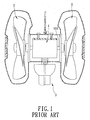
- a conventional electric fan is shown to include a motor 1, a pair of blade units 2 respectively driven by the motor 1, and a stand unit 3 for supporting a bottom of the motor 1.
- the blade units 2 rotate simultaneously so as to generate two streams of air flow blowing in opposite directions relative to an axis so as to dissipate heat.
- the object of the present invention is to provide an electric fan that is capable of overcoming the aforesaid drawback of the prior art.
- an electric fan of this invention comprises a motor, a pair of blade units, and a pair of engaging units.
- the motor has a motor shaft that defines an axis and that has two end segments which are axially opposite to each other. Each of the end segments has an engaging region. The engaging regions of the end segments of the motor shaft are disposed at angularly opposite positions relative to the axis.
- the blade units are coupled respectively to and are driven by the end segments of the motor shaft.
- Each of the blade units includes a hub that is sleeved on the respective one of the end segments, and a plurality of blades that extend from the hub.
- Each of the engaging units includes a first engaging member that is provided on the engaging region of a respective one of the end segments of the motor shaft, and a second engaging member that is provided on the hub of a respective one of the blade units and that engages the first engaging member, thereby securing the blade units to the end segments of the motor shaft, respectively.
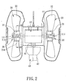
- the first preferred embodiment of an electric fan according to the present invention is shown to include a motor 10, a pair of blade units 20, and a pair of engaging units 50.
- the first preferred embodiment further includes a stand unit 40 for supporting the motor 10.
- the stand unit 40 includes a connecting rod 41 coupled to a bottom of the motor 10, and a stand 42 connected to the connecting rod 41.
- the motor 10 has a motor shaft 11 that defines an axis (L) and that has two end segments 111 axially opposite to each other. Each of the end segments 111 has an engaging region 113. The engaging regions 113 of the end segments 111 of the motor shaft 11 are disposed at angularly opposite positions relative to the axis (L).
- the blade units 20 are coupled respectively to and are driven by the end segments 111 of the motor shaft 11.
- Each of the blade units 20 includes a hub 21 that is sleeved on a respective one of the end segments 111, and a plurality of blades 22 that extend from the hub 21.
- Each of the engaging units 50 includes a first engaging member 51 that is provided on the engaging region 113 of a respective one of the end segments 111 of the motor shaft 11, and a second engaging member 52 that is provided on the hub 21 of a respective one of the blade units 20 and that engages the first engaging member 51, thereby securing the blade units 20 to the end segments 111 of the motor shaft 11, respectively.
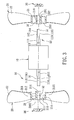
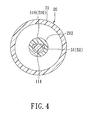
- each of the end segments 111 of the motor shaft 11 has a free end portion 112 with a non-circular cross-section.
- the free end portion 112 of each of the end segments 111 has a flat surface 116 that is disposed at the engaging region 113 and that defines the first engaging member 51 of the respective one of the engaging units 50.
- the hub 21 of each of the blade units 20 includes a sleeve part 212 that is sleeved on the respective one of the end segments 111 and that has a free end portion 213 with a non-circular cross-section.
- the free end portion 213 of the sleeve part 212 of the hub 21 of each of the blade units 20 has a flat surface 216 that defines the second engaging member 52 and that conforms to and that contacts the flat surface 116 of the free end portion 112 of the respective one of the end segments 111 of the motor shaft 11.
- the hub 21 of each of the blade units 20 further includes a hub base 210 and an outer annular wall 214 that extends axially from a periphery of the hub base 210 and that surrounds the sleeve part 212, which extends axially from an inner portion of the hub base 210.
- the hub base 210 has an inner side 2101 and an outer side 2102 that is opposite to the inner side 2101.
- the sleeve part 212 of the hub 21 of each of the blade units 20 further has an open outer end 211 that is opposite to the free end portion 213 of the sleeve part 212.
- Each of the end segments 111 of the motor shaft 11 has a threaded portion 114 that extends axially and outwardly through the open outer end 211 of the sleeve part 212 of the hub 21 of the respective blade unit 20.
- the electric fan further comprises a pair of screw nuts 30, each of which is disposed at the outer side 2102 of the hub base 210 of a respective blade unit 20and each of which engages threadedly the threaded portion 114 of a respective one of the end segments 111 of the motor shaft 11 so as to secure the blade units 20 to the end segments 111 of the motor shaft 11 after engagement between the first and second engaging members 51, 52 of the engaging units 50.
- each of the end segments 111 of the motor shaft 11 is formed with an engaging hole 116 that is disposed in the engaging region 113 and that defines the first engaging member 51 of the respective one of the engaging units 50.
- the sleeve part 212 of the hub 21 of each blade unit 20 is formed with a threaded hole 215.
- the second engaging member 52 of each of the engaging units 50 is in the form of a screw 30 that engages threadedly and that extends through the threaded hole 215 in the sleeve part 212 of the hub 21 of the respective one of the blade units 20 and that engages the engaging hole 116 in the respective one of the end segments 111 so as to secure the blade units 20 to the end segments 111 of the motor shaft 11 after engagement between the first and second engaging members 51, 52 of the engaging units 50.
- the sleeve part 212 of the hub 21 of each of the blade units 20 is formed with a blind hole 217 for insertion of the respective one of the end segments 111 of the motor shaft 11
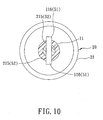
- the third preferred embodiment of this invention differs from the first preferred embodiment in that: the engaging region 113 of each end segment 111 is formed with at least one engaging protrusion 116 (in this embodiment, two engaging protrusions 116 are formed on the engaging region 113) that defines the first engaging member 51 of the respective one of the engaging units 50.
- the sleeve part 212 of the hub 21 of each blade unit 20 has a free end portion 213 formed with an engaging groove 215 (in this embodiment, two engaging grooves 215 are formed in the free end portion 213 of the sleeve part 212) which extends axially, which opens in a direction toward the motor 10, and which defines the second engaging member 52 of the respective one of the engaging units 50.
- Each engaging protrusion 116 of each of the end segments 111 extends into the corresponding engaging groove 215 in the free end portion 213 of the sleeve part 212 of the hub 21 of the respective one of the blade units 20, as best shown in Figure 10, thereby securing the blade units 20 to the end segments 111 of the motor shaft 11.
Landscapes
- Engineering & Computer Science (AREA)
- Mechanical Engineering (AREA)
- General Engineering & Computer Science (AREA)
- Structures Of Non-Positive Displacement Pumps (AREA)
Priority Applications (1)
| Application Number | Priority Date | Filing Date | Title |
|---|---|---|---|
| EP06000674A EP1808604A1 (fr) | 2006-01-13 | 2006-01-13 | Ventilateur électrique |
Applications Claiming Priority (1)
| Application Number | Priority Date | Filing Date | Title |
|---|---|---|---|
| EP06000674A EP1808604A1 (fr) | 2006-01-13 | 2006-01-13 | Ventilateur électrique |
Publications (1)
| Publication Number | Publication Date |
|---|---|
| EP1808604A1 true EP1808604A1 (fr) | 2007-07-18 |
Family
ID=36617261
Family Applications (1)
| Application Number | Title | Priority Date | Filing Date |
|---|---|---|---|
| EP06000674A Withdrawn EP1808604A1 (fr) | 2006-01-13 | 2006-01-13 | Ventilateur électrique |
Country Status (1)
| Country | Link |
|---|---|
| EP (1) | EP1808604A1 (fr) |
Cited By (1)
| Publication number | Priority date | Publication date | Assignee | Title |
|---|---|---|---|---|
| CN109944832A (zh) * | 2019-04-02 | 2019-06-28 | 威海卓锐羽绒制品股份有限公司 | 一种运行稳定的通风装置 |
Citations (6)
| Publication number | Priority date | Publication date | Assignee | Title |
|---|---|---|---|---|
| US2869651A (en) * | 1957-06-25 | 1959-01-20 | Gen Electric | Mounting arrangement for propeller type fan |
| US3937595A (en) * | 1974-07-05 | 1976-02-10 | Torin Corporation | Rotary fluid moving device with improved hub construction and method of making same |
| GB2014239A (en) | 1978-02-08 | 1979-08-22 | Chen Shean Huei | Double Fan |
| FR2463300A1 (fr) * | 1979-08-11 | 1981-02-20 | Bosch Gmbh Robert | Ventilateur avec un bout d'arbre monte dans le boitier d'un ensemble d'entrainement et qui fait saillie hors de ce boitier en etant muni d'une roue de ventilateur |
| US6224340B1 (en) * | 1998-02-20 | 2001-05-01 | Black & Decker, Inc. | Fan Retention system |
| US20040213687A1 (en) * | 2003-04-28 | 2004-10-28 | Chung-Yin Cheng | Heat dissipating fan assembly |
-
2006
- 2006-01-13 EP EP06000674A patent/EP1808604A1/fr not_active Withdrawn
Patent Citations (6)
| Publication number | Priority date | Publication date | Assignee | Title |
|---|---|---|---|---|
| US2869651A (en) * | 1957-06-25 | 1959-01-20 | Gen Electric | Mounting arrangement for propeller type fan |
| US3937595A (en) * | 1974-07-05 | 1976-02-10 | Torin Corporation | Rotary fluid moving device with improved hub construction and method of making same |
| GB2014239A (en) | 1978-02-08 | 1979-08-22 | Chen Shean Huei | Double Fan |
| FR2463300A1 (fr) * | 1979-08-11 | 1981-02-20 | Bosch Gmbh Robert | Ventilateur avec un bout d'arbre monte dans le boitier d'un ensemble d'entrainement et qui fait saillie hors de ce boitier en etant muni d'une roue de ventilateur |
| US6224340B1 (en) * | 1998-02-20 | 2001-05-01 | Black & Decker, Inc. | Fan Retention system |
| US20040213687A1 (en) * | 2003-04-28 | 2004-10-28 | Chung-Yin Cheng | Heat dissipating fan assembly |
Cited By (2)
| Publication number | Priority date | Publication date | Assignee | Title |
|---|---|---|---|---|
| CN109944832A (zh) * | 2019-04-02 | 2019-06-28 | 威海卓锐羽绒制品股份有限公司 | 一种运行稳定的通风装置 |
| CN109944832B (zh) * | 2019-04-02 | 2021-06-04 | 山东中鲁实业有限公司 | 一种运行稳定的通风装置 |
Similar Documents
| Publication | Publication Date | Title |
|---|---|---|
| US20060276122A1 (en) | Electric fan | |
| US7969050B2 (en) | External rotor and housing therefor | |
| EP1878923A3 (fr) | Turbine de ventilateur centrifuge et ventilateur centrifuge disposé avec la turbine | |
| CN105179271A (zh) | 离心风机或斜流风机 | |
| EP3767195B1 (fr) | Ensemble de guidage d'air et climatiseur pourvu de celui-ci | |
| WO2009069606A1 (fr) | Ventilateur centrifuge | |
| WO2003052905A3 (fr) | Unite d'entrainement electrique | |
| JP6180400B2 (ja) | 遠心送風機用羽根車および遠心送風機 | |
| US11732724B2 (en) | Ceiling fan blade and grommet | |
| KR102322341B1 (ko) | 소음 및 진동 저감용 송풍팬 및 이러한 송풍팬을 구비하는 공기조화기 | |
| CN101022872B (zh) | 聚合物风扇 | |
| EP1808604A1 (fr) | Ventilateur électrique | |
| US7121805B2 (en) | Electric fan with detachable blades | |
| KR200262719Y1 (ko) | 날개각 조정이 가능한 팬 | |
| CN203962505U (zh) | 轴流风机和具有其的空调器 | |
| WO2017154764A1 (fr) | Soufflante | |
| US10132321B2 (en) | Fan system having an external rotor | |
| EP1783375A1 (fr) | Ventilateur de moteur de rotor exterieur | |
| JP2015124712A (ja) | 送風機 | |
| JP7007404B2 (ja) | ファン用の駆動アセンブリ及びファン用の駆動アセンブリを備えるファン | |
| KR20100009256U (ko) | 효율 조정 기능을 갖는 유체 임펠러 | |
| EP1571345B1 (fr) | Ventilateur | |
| EP3505435B1 (fr) | Structure de dissipation de chaleur d'arbre d'essieu de roue motrice de motocyclette électrique | |
| MXPA05009192A (es) | Ventilador electrico. | |
| CN204458507U (zh) | 离心风叶的固定结构以及空调 |
Legal Events
| Date | Code | Title | Description |
|---|---|---|---|
| PUAI | Public reference made under article 153(3) epc to a published international application that has entered the european phase |
Free format text: ORIGINAL CODE: 0009012 |
|
| AK | Designated contracting states |
Kind code of ref document: A1 Designated state(s): AT BE BG CH CY CZ DE DK EE ES FI FR GB GR HU IE IS IT LI LT LU LV MC NL PL PT RO SE SI SK TR |
|
| AX | Request for extension of the european patent |
Extension state: AL BA HR MK YU |
|
| 17P | Request for examination filed |
Effective date: 20071114 |
|
| AKX | Designation fees paid |
Designated state(s): AT BE BG CH CY CZ DE DK EE ES FI FR GB GR HU IE IS IT LI LT LU LV MC NL PL PT RO SE SI SK TR |
|
| 17Q | First examination report despatched |
Effective date: 20080502 |
|
| STAA | Information on the status of an ep patent application or granted ep patent |
Free format text: STATUS: THE APPLICATION IS DEEMED TO BE WITHDRAWN |
|
| 18D | Application deemed to be withdrawn |
Effective date: 20100803 |