EP1808648A2 - Elekrischer Heizkörper - Google Patents
Elekrischer Heizkörper Download PDFInfo
- Publication number
- EP1808648A2 EP1808648A2 EP07380004A EP07380004A EP1808648A2 EP 1808648 A2 EP1808648 A2 EP 1808648A2 EP 07380004 A EP07380004 A EP 07380004A EP 07380004 A EP07380004 A EP 07380004A EP 1808648 A2 EP1808648 A2 EP 1808648A2
- Authority
- EP
- European Patent Office
- Prior art keywords
- horizontal
- conduits
- conduit
- vertical
- sections
- Prior art date
- Legal status (The legal status is an assumption and is not a legal conclusion. Google has not performed a legal analysis and makes no representation as to the accuracy of the status listed.)
- Withdrawn
Links
Images


Classifications
-
- F—MECHANICAL ENGINEERING; LIGHTING; HEATING; WEAPONS; BLASTING
- F24—HEATING; RANGES; VENTILATING
- F24H—FLUID HEATERS, e.g. WATER OR AIR HEATERS, HAVING HEAT-GENERATING MEANS, e.g. HEAT PUMPS, IN GENERAL
- F24H3/00—Air heaters
- F24H3/002—Air heaters using electric energy supply
Definitions
- the present invention relates to an electric heating radiator, comprising a body made up of horizontal and vertical conduits housing resistors, and of external fins attached to said conduits, the conduits and fins being metallic, preferably of aluminum.
- Radiators of the type set forth are already known in which the body is made up of at least two horizontal conduits, an upper and lower conduits, and a series of vertical conduits running between the horizontal conduits, opening into them, the horizontal conduits being closed at their ends.
- This body is completed with two series of external cooling fins located on either side of the horizontal and vertical conduit assembly, in a coplanar position on each side.
- the assembly thus formed is closed on the sides by means of respective covers housing the control elements such as the on-off switch, thermostats, etc.
- the assembly of the body is sub-divided, according to planes that are perpendicular to the horizontal conduits, into equal independent modules, each of which modules includes horizontal conduit sections, a vertical conduit running between the horizontal conduit sections, opening into them, and two vertical cooling fins running together with the vertical conduits, attached thereto.
- the horizontal conduit sections have an internal threading in different directions from their end sections.
- the attachment of consecutive modules is carried out by means of intermediate bushings which externally and after their end sections have a threading in different directions, coinciding with the inner threading of the horizontal conduit sections, such that when these intermediate bushings are turned in the corresponding direction they are screwed at the same time into the opposing ends of the horizontal tube sections of two consecutive modules.
- radiators In these radiators the body made up of the horizontal and vertical conduits is filled with oil or a similar thermal heat transfer fluid which is heated by means of resistors installed inside the body. This requires that the closure of the ends of the horizontal conduits be leak-tight for the purpose of preventing the heat transfer fluid from leaking.
- the weight of these radiators is relatively high since the horizontal and vertical conduit assembly is filled with oil or another similar heat transfer fluid. It must finally be indicated that the fact that the radiated is filled with oil entails an increase in the cost of the radiator.
- the object of the present invention is to eliminate the problems set forth by means of a radiator of the type indicated above but which does not have oil or a similar heat transfer fluid, such that its weight corresponds only to that of the components of the body, fins, side covers of the closure and resistors, its weight thus being much lighter than that of traditional radiators.
- the lower horizontal conduit of the radiator has a series of lower openings, each of which is located in extension of the vertical conduits, such that the body of the radiator is not leak-tight, but rather it opens at the lower part through the series of mentioned openings.
- each of the modules forming the radiator will include the horizontal conduit sections, preferably a lower section and another upper section, a vertical conduit running between the upper and lower horizontal conduit sections into which two vertical cooling fins open, a front fin and a rear fin, and a lower opening under the horizontal conduit section and as an extension of the vertical conduit.
- an insulated resistor is housed in each of the horizontal conduits of the radiator, which resistor is supported by the intermediate bushings acting as connecting elements between consecutive modules. These resistors are fed through taps traversing one of the closure covers of the ends of the horizontal conduits.
- the intermediate connecting bushings between consecutive modules can be internally provided with ribs determining interlocking or support points for the resistors running internally through each horizontal conduit. Each resistor is thus supported along the horizontal conduit on each and every one of the connecting bushings between consecutive modules.
- the radiator further includes one or more additional resistors in an intermediate position between the resistors housed in the horizontal conduits, parallel thereto. These additional resistors traverse the vertical conduits through aligned holes made in their walls, the resistors being adjusted to the contour of the holes and electrically insulated in relation to the same.
- the resistors will be single-tube resistors which are smooth or externally provided with fins, for example with a spiral fin. They can further be jacketed in an aluminum pipe in either case.
- the resistors installed in the horizontal conduits of the radiator will heat the air contained inside the same, being possible that at least part of this air will enter or exit through the lower openings.
- the hot air contained in the radiator will directly heat the walls of the different conduits and through these the cooling fins.
- the arrangement of the resistors and the heating of the air contained in the radiator will allow the temperature thereof to be uniform and the contained air to be completely dry due to the heating of the same.
- the radiator does not have oil or any other similar heat transfer fluid, therefore its weight will be much lighter and the manufacture thereof more cost-efficient.
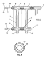
- Figure 1 shows a radiator including a body made up of two horizontal conduits, upper conduit 1 and a lower conduit 2, between which a series of vertical conduits 3 runs, opening into said horizontal conduits.
- the radiator further includes two series or assemblies of cooling fins, front fins with reference number 4 and rear fins with reference number 5, which are parallel and coincide with the vertical conduits 3.
- This radiator assembly is sub-divided into modules, according to planes perpendicular to the horizontal conduits 1 and 2, all this as can best be seen in Figure 3.
- the lower horizontal conduit 2 has openings 6 thereunder which are located as an extension of the vertical conduits 3.
- each of the modules forming the radiator comprises an upper horizontal conduit section having reference number 7 in Figure 3, a lower horizontal conduit section having reference number 8, a vertical conduit 3 running between and opening into the horizontal sections 7 and 8, a front fin 4 and rear fin 5.
- the attachment between consecutive modules is carried out by means of intermediate bushings 9.
- the horizontal sections 7 and 8 have inner threads in different directions after their end sections.
- the intermediate bushings 9 externally have threads in different after their end sections which are equal to the inner threads of sections 7 and 8. Therefore, when the bushings 9 are turned in the corresponding direction, they will be screwed into the end sections of the horizontal sections corresponding to consecutive modules.
- sections 7 form the conduit upper 1
- sections 8 form the lower horizontal conduit 2.
- Each of the discussed modules will further include a lower opening 6, opposite to the corresponding vertical conduit 3.
- the horizontal conduit 1 and 2 and vertical conduit 3 assembly will thus open to the exterior through the lower openings 6.
- a resistor 10 is installed through each of the conduits 1 and 2, which resistor is mounted in an end cap 11 which can be screwed onto the free end of the end bushing 9', acting as an upper closure cap.
- the electrical connections 12 will project from this cap 11.
- the intermediate bushings 9 may internally have ribs 12, Figure 4, which will be used as interlocking and support points for the resistor 10, said resistor thus being in a centered position along conduits 1 and 2.
- the radiator shown in Figure 1 can be completed with two closure covers which would cover the vertical sides and hide the connections 12, one of the covers further bearing the control elements or means, such as a switch, thermostats, operation signaling pilot lamp, etc.
- the body of the radiator made up of the vertical and horizontal conduits, opens to the exterior through the openings 6 and is completely empty, such that its weight is lighter in relation to traditional radiators of the same type which are filled with oil as the heat transfer fluid.
- the heating of the resistors 10 causes the heating of the air contained in the radiator, with freedom of expansion through the opening 6, causing the heating of the walls of the horizontal conduits 1 and 2 and vertical conduits 3 and through the latter the heating of the cooling fins 4 and 5.
- the radiator shown in Figure 5 is made up of independent modules that can be placed against and fixed to one another in a manner similar to that described in reference to Figure 3.
- One of these modules is shown in Figure 6.
- the radiator of the Figure 5 comprises an upper horizontal conduit 1 and a lower horizontal conduit 2, with vertical conduits, which are not shown, running between them.
- the radiator is completed with front fins 4 and rear fins 5.
- the modules forming this radiator include an upper horizontal conduit section 7, a lower horizontal conduit section 8, a vertical conduit 3 running between and opening into the horizontal sections 7 and 8, and a front fin 4 and rear fin 5.
- the walls of the vertical conduit 3 have opposing holes 14 which, in the radiator of Figure 5, will be aligned to receive other additional resistors 15, which will be located parallel to the resistors mounted in horizontal positions 1 and 2.
- the module of Figure 6 further has external fins 16 along the vertical conduits 3.
- the vertical conduits 3 are open at the bottom through the opening 6.
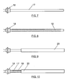
- FIGs 7 to 10 show other variants of resistors for the radiators of the Figures 1 and 5.
- the resistor is a single-tube type resistor 17, with a head 18 configured to be coupled on the opening of the horizontal conduits 1 and 2 or on the holes 14 of the additional resistors 15.
- resistors of Figures 9 and 10 correspond with the construction of resistors 7 and 8, incorporating an external aluminum jacket 20.
Landscapes
- Engineering & Computer Science (AREA)
- Physics & Mathematics (AREA)
- Thermal Sciences (AREA)
- Chemical & Material Sciences (AREA)
- Combustion & Propulsion (AREA)
- Mechanical Engineering (AREA)
- General Engineering & Computer Science (AREA)
- Heat-Exchange Devices With Radiators And Conduit Assemblies (AREA)
- Central Heating Systems (AREA)
Applications Claiming Priority (1)
| Application Number | Priority Date | Filing Date | Title |
|---|---|---|---|
| ES200600072A ES2259571B1 (es) | 2006-01-12 | 2006-01-12 | Radiador electrico de calefaccion. |
Publications (2)
| Publication Number | Publication Date |
|---|---|
| EP1808648A2 true EP1808648A2 (de) | 2007-07-18 |
| EP1808648A3 EP1808648A3 (de) | 2013-01-09 |
Family
ID=37054803
Family Applications (1)
| Application Number | Title | Priority Date | Filing Date |
|---|---|---|---|
| EP20070380004 Withdrawn EP1808648A3 (de) | 2006-01-12 | 2007-01-09 | Elekrischer Heizkörper |
Country Status (2)
| Country | Link |
|---|---|
| EP (1) | EP1808648A3 (de) |
| ES (1) | ES2259571B1 (de) |
Cited By (4)
| Publication number | Priority date | Publication date | Assignee | Title |
|---|---|---|---|---|
| AU2008344134B2 (en) * | 2007-12-31 | 2011-08-25 | Lg Electronics Inc. | A method and an apparatus for processing an audio signal |
| WO2012136229A3 (de) * | 2011-04-05 | 2013-04-04 | Koenig Harry | Gliederheizkörper |
| EP2933595A1 (de) * | 2014-03-28 | 2015-10-21 | Rettig ICC B.V. | Konvektor-Wärmeübertrager |
| WO2016046804A1 (en) * | 2014-09-26 | 2016-03-31 | Fondital S.P.A. | Radiator elements, manufacturing method thereof and joining method for joining the radiator elements in a battery |
Family Cites Families (8)
| Publication number | Priority date | Publication date | Assignee | Title |
|---|---|---|---|---|
| DE1679446A1 (de) * | 1967-10-19 | 1970-01-29 | Thomas Fa Robert | Verkleidung fuer fahrbare oelgefuellte Elektro-Radiatoren |
| AT308253B (de) * | 1969-09-05 | 1973-06-25 | Burg Konrad Fa | Elektrischer Raumheizkörper von der Form eines Radiators |
| GB9302743D0 (en) * | 1993-02-11 | 1993-03-24 | Dimplex Uk Ltd | Electrical column radiator |
| ES2114825B1 (es) * | 1996-06-19 | 1999-02-16 | Castanon Moran Teresa | Radiador electrico de aceite. |
| IT1308708B1 (it) * | 1999-02-17 | 2002-01-10 | De Longhi Spa | Radiatore di tipo mobile a funzionamento indipendente |
| ES2188355B1 (es) * | 2001-03-07 | 2004-10-01 | Luis Velez Diaz | Modulo de radiador - convector electrico. |
| FR2823838B1 (fr) * | 2001-04-23 | 2004-01-09 | Francoise Albertini | Radiateur electrique autonome a fluide caloporteur |
| ES1055066Y (es) * | 2003-07-14 | 2004-04-16 | Electroetxea S L | Radiador electrico de calefaccion. |
-
2006
- 2006-01-12 ES ES200600072A patent/ES2259571B1/es not_active Expired - Fee Related
-
2007
- 2007-01-09 EP EP20070380004 patent/EP1808648A3/de not_active Withdrawn
Cited By (5)
| Publication number | Priority date | Publication date | Assignee | Title |
|---|---|---|---|---|
| AU2008344134B2 (en) * | 2007-12-31 | 2011-08-25 | Lg Electronics Inc. | A method and an apparatus for processing an audio signal |
| US9659568B2 (en) | 2007-12-31 | 2017-05-23 | Lg Electronics Inc. | Method and an apparatus for processing an audio signal |
| WO2012136229A3 (de) * | 2011-04-05 | 2013-04-04 | Koenig Harry | Gliederheizkörper |
| EP2933595A1 (de) * | 2014-03-28 | 2015-10-21 | Rettig ICC B.V. | Konvektor-Wärmeübertrager |
| WO2016046804A1 (en) * | 2014-09-26 | 2016-03-31 | Fondital S.P.A. | Radiator elements, manufacturing method thereof and joining method for joining the radiator elements in a battery |
Also Published As
| Publication number | Publication date |
|---|---|
| ES2259571A1 (es) | 2006-10-01 |
| ES2259571B1 (es) | 2007-10-01 |
| EP1808648A3 (de) | 2013-01-09 |
Similar Documents
| Publication | Publication Date | Title |
|---|---|---|
| US20030007790A1 (en) | Water heater | |
| US20100043415A1 (en) | Extruded gas cooler | |
| CN103974839B (zh) | 用于机动车辆的电加热装置和相关联的空调和/或加热单元 | |
| CN107710867B (zh) | 流体加热装置 | |
| US5186245A (en) | Flow control baffle for radiator in-tank cooler | |
| US11933520B2 (en) | Fluid-heating device and manufacturing method thereof | |
| WO2013157430A1 (ja) | 加熱装置 | |
| US4516630A (en) | Motorcycle radiator | |
| JP5996772B2 (ja) | 自動車用の流体を電気的に加熱するための装置及びこの加熱装置を組み立てる方法 | |
| US12281820B2 (en) | Electric device for heating a heat transfer fluid for a motor vehicle | |
| CN110431924A (zh) | 用于容纳电子元件的套管 | |
| US10669925B2 (en) | Vehicle fan shroud de-icing assembly | |
| US10609766B2 (en) | Heater for electronic thermostat and method for manufacturing the same | |
| KR200387377Y1 (ko) | 히트파이프 열교환기의 전열관 구조 | |
| WO2015000699A1 (en) | Canister cooling | |
| KR102739173B1 (ko) | 차량용 냉각수 히터 | |
| CN101137883B (zh) | 冷却设备 | |
| WO2011016763A1 (en) | Electrical heating device for vehicles | |
| EP2000747A2 (de) | Modularer elektrischer Heizkörper | |
| WO2017208687A1 (ja) | 流体加熱装置 | |
| ES2259571B1 (es) | Radiador electrico de calefaccion. | |
| KR20210121225A (ko) | 차량 엔진룸의 배열체 | |
| EP2037116B1 (de) | Multifunktionsmodul für einen Verbrennungsmotor | |
| RU2179693C2 (ru) | Модульный биметаллический радиатор для бытовых систем отопления | |
| CN113604764B (zh) | 一种伸缩罩的保温罩壳 |
Legal Events
| Date | Code | Title | Description |
|---|---|---|---|
| PUAI | Public reference made under article 153(3) epc to a published international application that has entered the european phase |
Free format text: ORIGINAL CODE: 0009012 |
|
| AK | Designated contracting states |
Kind code of ref document: A2 Designated state(s): AT BE BG CH CY CZ DE DK EE ES FI FR GB GR HU IE IS IT LI LT LU LV MC NL PL PT RO SE SI SK TR |
|
| AX | Request for extension of the european patent |
Extension state: AL BA HR MK YU |
|
| PUAL | Search report despatched |
Free format text: ORIGINAL CODE: 0009013 |
|
| AK | Designated contracting states |
Kind code of ref document: A3 Designated state(s): AT BE BG CH CY CZ DE DK EE ES FI FR GB GR HU IE IS IT LI LT LU LV MC NL PL PT RO SE SI SK TR |
|
| AX | Request for extension of the european patent |
Extension state: AL BA HR MK RS |
|
| RIC1 | Information provided on ipc code assigned before grant |
Ipc: F24H 3/00 20060101AFI20121203BHEP |
|
| AKY | No designation fees paid | ||
| REG | Reference to a national code |
Ref country code: DE Ref legal event code: R108 |
|
| REG | Reference to a national code |
Ref country code: DE Ref legal event code: R108 Effective date: 20130911 |
|
| 17P | Request for examination filed |
Effective date: 20131022 |
|
| RBV | Designated contracting states (corrected) |
Designated state(s): AT BE BG CH CY CZ DE DK EE ES FI FR GB GR HU IE IS IT LI LT LU LV MC NL PL PT RO SE SI SK TR |
|
| GRAP | Despatch of communication of intention to grant a patent |
Free format text: ORIGINAL CODE: EPIDOSNIGR1 |
|
| INTG | Intention to grant announced |
Effective date: 20150826 |
|
| STAA | Information on the status of an ep patent application or granted ep patent |
Free format text: STATUS: THE APPLICATION IS DEEMED TO BE WITHDRAWN |
|
| 18D | Application deemed to be withdrawn |
Effective date: 20160106 |