EP1808768A2 - Surveillance à distance automatique et système de diagnostic ainsi que procédé de communication pour la communication entre un automate programmable industriel et une unité centrale - Google Patents
Surveillance à distance automatique et système de diagnostic ainsi que procédé de communication pour la communication entre un automate programmable industriel et une unité centrale Download PDFInfo
- Publication number
- EP1808768A2 EP1808768A2 EP06255440A EP06255440A EP1808768A2 EP 1808768 A2 EP1808768 A2 EP 1808768A2 EP 06255440 A EP06255440 A EP 06255440A EP 06255440 A EP06255440 A EP 06255440A EP 1808768 A2 EP1808768 A2 EP 1808768A2
- Authority
- EP
- European Patent Office
- Prior art keywords
- monitoring
- unit
- diagnostics
- data
- monitored
- Prior art date
- Legal status (The legal status is an assumption and is not a legal conclusion. Google has not performed a legal analysis and makes no representation as to the accuracy of the status listed.)
- Granted
Links
Images


Classifications
-
- G—PHYSICS
- G05—CONTROLLING; REGULATING
- G05B—CONTROL OR REGULATING SYSTEMS IN GENERAL; FUNCTIONAL ELEMENTS OF SUCH SYSTEMS; MONITORING OR TESTING ARRANGEMENTS FOR SUCH SYSTEMS OR ELEMENTS
- G05B23/00—Testing or monitoring of control systems or parts thereof
- G05B23/02—Electric testing or monitoring
- G05B23/0205—Electric testing or monitoring by means of a monitoring system capable of detecting and responding to faults
- G05B23/0218—Electric testing or monitoring by means of a monitoring system capable of detecting and responding to faults characterised by the fault detection method dealing with either existing or incipient faults
- G05B23/0243—Electric testing or monitoring by means of a monitoring system capable of detecting and responding to faults characterised by the fault detection method dealing with either existing or incipient faults model based detection method, e.g. first-principles knowledge model
- G05B23/0245—Electric testing or monitoring by means of a monitoring system capable of detecting and responding to faults characterised by the fault detection method dealing with either existing or incipient faults model based detection method, e.g. first-principles knowledge model based on a qualitative model, e.g. rule based; if-then decisions
- G05B23/0248—Causal models, e.g. fault tree; digraphs; qualitative physics
-
- G—PHYSICS
- G05—CONTROLLING; REGULATING
- G05B—CONTROL OR REGULATING SYSTEMS IN GENERAL; FUNCTIONAL ELEMENTS OF SUCH SYSTEMS; MONITORING OR TESTING ARRANGEMENTS FOR SUCH SYSTEMS OR ELEMENTS
- G05B23/00—Testing or monitoring of control systems or parts thereof
- G05B23/02—Electric testing or monitoring
- G05B23/0205—Electric testing or monitoring by means of a monitoring system capable of detecting and responding to faults
- G05B23/0259—Electric testing or monitoring by means of a monitoring system capable of detecting and responding to faults characterized by the response to fault detection
- G05B23/0275—Fault isolation and identification, e.g. classify fault; estimate cause or root of failure
- G05B23/0278—Qualitative, e.g. if-then rules; Fuzzy logic; Lookup tables; Symptomatic search; FMEA
-
- G—PHYSICS
- G05—CONTROLLING; REGULATING
- G05B—CONTROL OR REGULATING SYSTEMS IN GENERAL; FUNCTIONAL ELEMENTS OF SUCH SYSTEMS; MONITORING OR TESTING ARRANGEMENTS FOR SUCH SYSTEMS OR ELEMENTS
- G05B2219/00—Program-control systems
- G05B2219/30—Nc systems
- G05B2219/33—Director till display
- G05B2219/33303—Expert system for diagnostic, monitoring use of tree and probability
Definitions
- This invention relates generally to a Monitoring and Diagnostics system and, more particularly, to a communication method, in particular to a communication method for communicating between a Programmable Logic Controller and a central unit.
- M&D systems Monitoring and Diagnostics systems
- RM&D systems Remote Monitoring and Diagnostics systems
- RM&D systems Remote Monitoring and Diagnostics systems
- response time i.e. the time span between the fault event and the initiation of appropriate actions. It is desired to have short response times, because, for example, apparatus faults can lead to apparatus unavailability, further damage to the apparatus, or to an increased risk (e.g. in the case of medical equipment or of traffic control systems).
- the response time depends on the availability of a human operator. For example, if a wind turbine connected to a M&D system faults, it usually stops its operation until an operator is able to analyze its condition, to establish that a reset of the turbine is feasible and to perform the reset, During that period, the turbine is unavailable and does not produce energy. To improve the response time, an operator needs to be available when the turbine faults. However, permanent operator availability is costly, and is still not a guarantee for a short response time, e.g. in the case of simultaneous faults in multiple apparatuses.
- Protocols allowing for a more flexible data transmission from or to Programmable Logic Controllers are also known, for example the protocols according to the norms IEC 60870-5-104 and JEC 61850. These protocols allow transmitting data along with information regarding the structure of the transmitted data. However, both the data and the information are transmitted in the same channel, whereby the performance of the protocol is degraded. Also, a clear distinction between raw data and information can be desirable e.g. for optional compatibility with respect to other static protocols.
- a Monitoring and Diagnostics System comprising:
- a communication method for communicating between a first Programmable Logic controller and at least one of a second Programmable Logic controller and a central unit comprising:
- Monitoring and Diagnostics system includes, a monitoring unit and a monitored unit, and communication means between the monitoring unit and the monitored unit.
- the monitored unit includes data acquisition means for providing fault data of the monitored unit and the communication means are adapted to communicate the fault data from the monitored unit to the monitoring unit.
- the monitoring unit includes a reasoning engine having diagnostics knowledge for analyzing the information contained in the fault data and being adapted to deduce diagnostics information from said diagnostics knowledge and from the information.
- a system for the automated handling of faults in apparatuses for example, in a plurality of remotely located apparatuses, through the use of diagnostics knowledge is provided by combining a Monitoring and Diagnostics system with a reasoning engine, such as e.g. a rule based expert analysis engine comprising diagnostics knowledge.
- a reasoning engine such as e.g. a rule based expert analysis engine comprising diagnostics knowledge.
- Such reasoning engines are traditionally used in database applications, where they are used for analyzing complex sets of data and for deducing appropriate decisions. Examples include score card engines for bank credit decisions, or spell checking systems in word processors.
- the Monitoring and Diagnostics system can also provide diagnostics information, i.e. information relating to the nature or the origin of a fault.
- the system can also provide suggestions on the next steps for diagnostics or repair of the apparatus.
- the reasoning engine includes means to analyze the fault data of the apparatus and to apply the diagnostics knowledge to determine a course of action.
- the diagnostics knowledge can be updated easily as the knowledge / expertise on connect fault procedures increases.
- An advantage of the present invention is that the need of human local access and of human remote access to the apparatuses can be minimized.
- a further advantage is that a reduction of the response time is achievable.
- a further advantage is that cost efficiency is improved.
- a further advantage is that the consistency for the handling of apparatus faults is improved, because due to the diagnostics knowledge, the system goes through well-defined fault handling procedures and analysis steps.
- the reasoning engine includes at least one element taken from the group consisting of Bayesian belief networks, causality engines, rules engines, decision trees, classification trees, simulation engines, neural networks, database comparisons, and combinations thereof.
- the diagnostics knowledge includes at least one element taken from the group consisting of Bayesian graphs, procedures, sets of expert rules, database entries, and combinations thereof.
- the reasoning engine is adapted to analyze a cross-relation between a plurality of faults contained in the fault data, and the M&D system includes control means for controlling the settings or working parameters of the monitored unit. Further, the M&D system includes a database recording fault data and the diagnostics information for further use. Additionally, the M&D system includes means for updating the diagnostics knowledge and includes a plurality of monitored units.
- the reasoning engine is adapted to provide, depending on the information contained in the fault data, suggestions for possible next steps to be undertaken.
- the reasoning engine is further adapted to determine and initiate, depending on the information contained in the fault data, a course of action to be taken.
- the M&D system also includes cross-validation means for checking if the initiated course of action was successfully performed and the monitoring unit is remotely monitored from the monitored unit, i.e., for example, separate from the monitored unit, located at a distance farther than 10m, 100m, 1km, or 10km, or at a location that is difficult or inconvenient to access from the monitoring unit.
- the monitored unit is a wind turbine, and one possible course of action to be taken is an automatic reset of the wind turbine.
- the communication means are such that the fault data to be communicated can be selected, e.g. by fault, by fault type, by monitored unit, or by a cluster of monitored units.
- the Monitoring and Diagnostics System comprises a monitoring unit and a monitored unit remotely located from the monitoring unit, and communication means between the monitoring unit and the monitored unit, whereby the monitored unit comprises data acquisition means for providing fault data of the monitored unit, the communication means are adapted to communicate the fault data from the monitored unit to the monitoring unit, and the monitoring unit comprises a reasoning engine comprising diagnostics knowledge for analyzing the information contained in the fault data and being adapted to deduce diagnostics information from said diagnostics knowledge and from said information.
- a communication method for communicating between a first Programmable Logic Controller and at least one of a second Programmable Logic Controller and a central unit is provided, in which a description file is provided.
- a communication method for communicating between a first Programmable Logic Controller and at least one of a second Programmable Logic Controller and a central unit which includes the first Programmable Logic Controller and at least one of the second Programmable Logic Controller and the central unit communicate data items via a communication channel according to an essentially deterministic transfer structure.
- the first and the at least one of the second Programmable Logic Controller and the central unit provides a separate description file containing a description of the information contained in the data items or in the sequence of data items.
- the description file e.g., an XML File
- the description file is an XML file.
- the data items are transmitted in a predetermined sequence, so that the information is transmitted in a fixed order in the sequence of data items.
- the data items in the communication channel, or according to the transfer structure contain no describing elements.
- the description file is transmitted between the first Programmable Logic Controller and at least one of the second Programmable Logic Controller and the central unit cyclically with a specifiable cycle.
- the description file is transmitted between the first Programmable Logic Controller and the at least one of the second Programmable Logic Controller and the central unit in response to a pre-defined event or condition.
- the description file is transmitted, and then raw data is transmitted via the communication channel.
- the raw data is transmitted periodically, whereas the description file is only transmitted once in a communication and describes the raw data of each period.
- An advantage of this communication method is that the second Programmable Logic Controller or the central unit can be enabled to locate data provided by the first Programmable Logic Controller on its own, or vice versa.
- the description file it is possible to locate a particular information, or data point, and to know in what provided structure it could be read. Additionally, it is possible to locate the relevant data, i.e. the values, behind which stands a real supply of interest.
- the data and the information are transmitted in separate channels, leading to a good performance of the protocol. Also, a clear distinction between raw data and information allows for optional compatibility with respect to other protocols.
- Fig. 1. illustrates an embodiment of a monitoring unit 100 connected via communication means 102 to a plurality of remotely located monitored units 104.
- the term remote refers to any unit that is physically separated from the monitoring unit by more than a certain distance (e.g. more than 100m, 1km, or 10km), or that is otherwise difficult or inconvenient to access directly.
- connection means 102 are divided into a network 106 for a cluster of the monitored units and a connection 108 between network 106 and monitoring unit 100.
- the cluster of monitored units 100 may include one or several or all units, and several clusters may also be present.
- Network 106 is typically a local area network and communication means 102 uses, in some embodiments, dedicated connections, such as T1 lines, or dial-up modem connections, connections by cable, by optical fiber, by wireless connection, and other connection means.
- Communication means 102 also includes, in one embodiment, additional infrastructure elements, such as a network server, a router, etc.
- additional infrastructure elements such as a network server, a router, etc.
- file transfer protocol ftp
- Email, TCPIIP, I-JTTP and other protocols may be utilized as well.
- the monitored unit 104 is further illustrated in Fig. 2. It includes a system 110 for controlling monitored unit 104 and for providing fault data, which is connected to communication means 102 via a communication interface 112.
- the term fault data is intended to include data or messages that are only sent in the case of a fault event, and that may contain information on the nature of the fault.
- the term fault data in one embodiment, also includes data or messages that are sent irrespective of whether a fault occurs or not, and that may contain information on the occurrence of a fault, and optionally on the nature of the fault.
- System 110 for controlling the monitored unit and for providing fault data includes at least one sensor 114 for measuring data from monitored unit 104, e.g.
- System 110 further comprises a data processing means 116, e.g. a Programmable Logic Controller, for processing the data measured in sensors 114, and a central unit 118 for controlling functions of monitored unit 104, Sensors 114 are connected to data processing means 116, which is connected to central unit 118, which in turn is connected to communication interface 112.
- system 110 includes controlling means 120 for controlling or influencing monitored unit 104, e.g.
- controlling means 120 are connected to central unit 118, via data processing means 116, e.g. a Programmable Logic Controller.
- Data processing means 116 for sensors 114 and data processing means 116 for controlling means 120 are two separate units as shown in Fig.. Alternatively they are the same unit.
- Fig. 3 illustrates monitoring unit 100. including a computer or a network of computers.
- Monitoring unit 100 includes a communication interface 122 connected to communication means 102 for receiving fault data from monitored units 104 and for communicating with monitored units 104.
- communication interface 122 includes at least one of a modem, a router, and a network card.
- Monitoring unit 104 further includes a reasoning engine 124, e.g. a rules engine, for analyzing the fault data and for providing diagnostics information, and optionally for suggesting possible next steps to be undertaken and/or for initiating automatic remedial actions in monitored unit 104, such as a reset, a controlled shutdown, braking, the activation of a replacement unit, or a controlled reduction of activity.
- a reasoning engine 124 e.g. a rules engine
- reasoning engine 124 includes a diagnostics knowledge 126, e.g. a set of expert rules, and a processor 128.
- Reasoning engine 124 is further connected to an optional input device 130, an output device 132, and an optional services database 134.
- Reasoning engine 124 is connected to communications interface 122 either directly or via an optional parsing means 136 for analyzing the incoming fault data and for generating from the fault data values that can be read by reasoning engine 124.
- the connection further optionally comprises a processor 138 for sending out signals to monitored unit 104, e.g. for transmitting commands for initiating remedial actions.
- the data is processed by data processing means 116, and information is transmitted to central unit 118 for controlling monitored unit 104.
- the data is further processed, and fault data is generated.
- the fault data is then transmitted, via communication interface 112 of the monitored unit 104, communication means 102, and communication interface 122 of monitoring unit 100, to monitoring unit 100.
- the fault data may then be further processed by parsing means 136 and is transmitted to reasoning engine 124.
- processor 128 analyses the fault data according to diagnostics knowledge 126.
- diagnostics information is generated and outputted on output device 132.
- Diagnostics information includes information regarding the origin or the nature of a fault, further details regarding the fault, e.g. time, location, severity, duration, summary information regarding the fault, and the like.
- a suggestion for next steps can be generated.
- reasoning engine 124 may also initiate an appropriate automatic action of monitored unit 104.
- the request for this action is sent back to monitored unit 104.
- the request is optionally processed by a processor 138 for sending out signals, and is then sent out to monitored unit 104 via communication interface 122 and communications means 102.
- the request signal is received, via communication interface 112, by central unit 118. If appropriate, it is transmitted to data processing means 116, and to controlling means 120 for executing the request.
- system 110 for controlling monitored unit 104 and for providing fault data collects the data to transmit to monitoring unit 100, or to the centralized system. Choosing the data to transmit depends on communication costs and ability to diagnose the specific fault.
- communication means 102 provide high-speed connectivity, the desire is to send a large amount of data.
- communication means 102 also contains communications devices, such as dial-up modems, and the transmission speeds may vary.
- One aspect of the invention is to provide configuration data to system 110 for controlling monitored unit 104 and for providing fault data that allows the data to be selected by fault and by monitored unit 104.
- the communication time and cost can be adjusted to the respective needs while still achieving the desired availability goals with respect to the fault data and the appropriate reaction by monitoring unit 100.
- system 110 for controlling monitored unit 104 and for providing fault data will compare the current state of monitored unit 104 to the state when the fault message was sent. If the condition is the same, then system 110 for controlling the monitored unit 104 and for providing fault data processes the request. In both circumstances, a feed back message is sent to the monitoring unit 100 for confirmation.
- the state of monitored unit 104 is defined as changed if new faults have occurred since the original message, or if the monitored unit was subject to other requests.
- parsing means 136 in this invention may interpret the data retrieved from monitored unit 104 and may construct the variable input in a suitable form for reasoning engine 124 or for diagnostics knowledge 126.
- the input to this component is also configurable, particularly for retrieving the expected settings of monitored unit 104 and limits on historical fault frequency. Parsing component 136, reasoning engine 124, and diagnostics knowledge 126 are designed to work together. While specific decisions may be made to implement some calculations in parse component 136, other embodiments implement these within the other components.
- Reasoning engine 124 includes a compute processor 128 where a software program that interprets diagnostics knowledge 126 and the input variables for the rule executed. Reasoning engine 124, in one embodiment, creates advisory messages that represent diagnostics information via output device 132. Reasoning engine 124, in another embodiment, also creates suggestions for further steps, or actions that should be followed. The actions include, in one embodiment, service actions to be performed by, at least one of a remote service engineer and an on-site service engineer, and/or actions to be handled automatically by system 110 for controlling monitored unit 104 and for providing fault data. Automatic actions are sent out via the optional processor for sending out signals 138, to the appropriate monitored unit 104 as described above.
- reasoning engine 124 is, in one embodiment, a rules engine, or rule-based processor, or rule system, having a set of expert rules as diagnostics knowledge 126. Then, the rules contain the business logic for handling each fault.
- the rule design is robust so that even when input data is incomplete, the rules allow for the creation of appropriate diagnostic recommendations. For instance, with missing inputs, the diagnostic advisory text may state that certain data is incomplete or unavailable, so that a definite recommendation cannot be given, and that the engineers should retrieve the data manually and continue to follow the fault procedures. If the data cannot be retrieved from monitored unit 104 (for instance if fault history is no longer available), then the output could be that the engineer must retrieve the data from other sources or in some other manner to determine the appropriate action.
- the rule style for each fault is similar, although the specific variables that must be checked vary. As a result each rule is typically implemented manually. A test procedure to validate that the rule has been implemented correctly is typically utilized. This test procedure includes, in one embodiment, checking the result of the rules with all combinations of expected input variables. Another aspect of the rules is that multiple faults can be analyzed simultaneously. Since a fault can trigger other faults, it is advisable that all the current active faults be assessed. For example, in one embodiment a certain action is performed if this action is not in conflict with any of the detected faults. Therefore, the rules are generally constructed so that although each fault is assessed independently, if any condition prevents an event for one fault of the active faults, no request will be created for the specific event.
- a Bayesian network is employed in the Monitoring and Diagnostics system, in which, diagnostics knowledge 126 is represented as a Bayesian graph.
- diagnostics knowledge 126 is represented as a Bayesian graph.
- reasoning engine 124 include causality engines, rules engines, decision trees, classification trees, simulation engines such as Monte-Carlo methods and simulations of underlying physical models for the monitored unit, neural networks, database comparisons, and combinations thereof.
- Further examples for a representation of diagnostics knowledge 126 can then be procedures, sets of expert rules, database entries, or combinations thereof.
- Reasoning engine 124 uses an advanced pattern of fault data. For example, the occurrence of a predetermined number of faults in a given turbine and in a predetermined time interval.
- the faults may further be filtered or weighted by fault type, by time, by a correlation with other faults, or by other factors. In this manner, a cross-relation between a plurality of faults can be analyzed and exploited for diagnostic purposes.
- Diagnostics knowledge 126 may be updated as the knowledge expertise on correct fault procedures increases.
- the updating in one embodiment, is performed automatically via machine learning, e.g. in the context of neuronal networks or Bayesian networks.
- the updating is performed manually, e.g. by updating the expert rules in a rules engine.
- Optional service database 132 contains the record of the fault and the follow-up corrective actions for maintaining history and audit trial. It is physically composed of several tables in at least one true database instance. This data is used to document what has happened on the system. It may also be used interactively for case management, although many other features would be utilized for a case handling system.
- the database in one embodiment, provides an audit trail of the steps of the M&D process for debugging purposes and historical reporting.
- monitored unit 104 includes a wind turbine.
- a possible remedial action in the case of turbine faults is a reset, which may be initiated automatically via processor 138 of monitoring unit 100 for sending out signals, and is performed by controlling means 120, which in this embodiment includes a reset mechanism.
- the remedial actions in a turbine include a reset of the turbine. After the reset and an optional startup phase, the turbine returns to normal operation. The reset is handled automatically by the M&D system components. Other possible actions include service actions to be taken by a remote service engineer or by an on-site service engineer.
- Fig. 4 illustrates a communication method according to a further embodiment of the invention.
- the method is used for communication between central unit 118 and Programmable Logic Controller 116 in monitored unit 104, or between two Programmable Logic Controllers 116 in monitored unit 104. Also, the method is used in Wind Farm Management Control Systems.
- the above are solely illustrative examples only and in no way limit the scope of the invention.
- Central unit 118 and Programmable Logic Controller 116 are connected via a station bus, to which various other devices are optionally connected.
- the components are connected via an Ethernet or via switched Ethernet technology, or via a similar technology.
- the connection includes an interface for configuration tools for central unit 118 and/or for Programmable Logic Controller 116.
- the connection uses at least one of copper lines, consist of optical fibers, wireless LAN technology, and other connection means.
- the connection alternatively includes additional infrastructure elements, such as a network server, a router, a switch, etc.
- the communication method, or communication protocol uses a communication channel 140 for transmitting data items, or data elements, or data points, according to an essentially static or deterministic transfer structure.
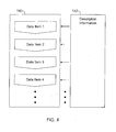
- a description file 142 for describing the information in static communication channel 140.
- An essentially deterministic transfer structure governs the transfer of data items according to a predetermined set of static rules.
- the data items are transmitted in a predetermined sequence, so that the information is transmitted in a fixed order in the sequence of data items.
- this example includes sequences, in which the order of data items is fixed, so that in each communication, the position at which a given information can be found is the same in the sequence of data items.
- an essentially deterministic transfer structure also includes variations of such sequences of fixed order, in which the length of a certain set of data items is variable according to predetermined rules.
- the set of data items may be inserted or omitted according to predetermined rules, or in which one of a list of several sequences of data items is selected for a part of the communication depending on some predetermined condition.
- Such predetermined rules are determined in the firmware of Programmable Logic Controller 116, and/or are determined at the beginning of each communication, and/or are examples for communication protocols that implement an essentially deterministic transfer structure including signal oriented protocols, according to which data items are transmitted without any description elements, and object oriented protocols, according to which data items are transmitted with description elements.
- the description elements can come in the form of necessary or optional attributes.
- a data item of communication channel 140 essentially comprises a certain value to be transmitted.
- a data item also includes other parameters related to the transmitted value, such as a system ID, a data item ID, a data type indicator (e.g. integer, floating point, array, optionally including an array length in the latter case), a timestamp, a quality indicator, etc).
- a data type indicator e.g. integer, floating point, array, optionally including an array length in the latter case
- a timestamp e.g. integer, floating point, array, optionally including an array length in the latter case
- a separate description file 142 which describes the information in static communication channel 140.
- the description file generally provides information on how the sequence of data items in static communication channel 140 is organized, and/or on the information content of data items in static communication channel 140. Examples for description elements are an indicator indicating which data items are of relevance in a particular situation, which data items merely contain default values or checksums or the like, which data items contain a certain kind of physical or technical information, or information regarding the communication structure of communication channel 140.
- central unit 118 may interpret incoming data according to the description file, and therefore the communication may not be limited to one specific protocol, e.g. in the case that Programmable Logic Controller 116 is replaced or updated. At the same time, compatibility with respect to existing protocols is maintained.
- description file 142 a part of the possible parameters of the data item (system ID, etc.) is contained in description file 142 and omitted in static communication channel 140.
- An advantage of this procedure is that the description file is transmitted only once during a communication, whereas a given sequence of data items is transmitted periodically. Therefore, the amount of data to transmit is reduced if parameters that do not change from period to period are included in description file 142 and are omitted from static channel 140.
- Description file 142 is typically transmitted before data items are sent via static communications channel 140.
- the description file is transmitted cyclically with a specifiable regular or irregular cyclus.
- the length of the cyclus is, in one embodiment, given in terms of temporal duration, the amount of transmitted data items, the count of other events, or of a combination thereof.
- the description file is optionally transmitted cyclically, i.e. in response to pre-determined or specifiable events or conditions.
- Such events or conditions include, for example, initialization of central unit 118 or of Programmable Logic Controller 116, setup of a communication between two units or to a third unit; request or necessity for refreshing the data description; change of the data description or of the protocol in a transmitting unit (e.g. in the Programmable Logic Controller 116); and change of the data description or of the protocol in a receiving unit (e.g. in central unit 118).
- monitoring unit 102 communication means 104 monitored unit 106 network 108 connection 110 system 112 communication interface 114 sensors 116 data processing means 118 central unit 120 controlling means 122 communication interface 124 reasoning engine 126 diagnostics knowledge 128 processor 130 input device 132 output device 134 services database 136 parsing means 138 processor 140 communication channel 142 description file
Landscapes
- Physics & Mathematics (AREA)
- Engineering & Computer Science (AREA)
- General Physics & Mathematics (AREA)
- Automation & Control Theory (AREA)
- Fuzzy Systems (AREA)
- Mathematical Physics (AREA)
- Quality & Reliability (AREA)
- Testing And Monitoring For Control Systems (AREA)
- Programmable Controllers (AREA)
- Selective Calling Equipment (AREA)
Applications Claiming Priority (1)
| Application Number | Priority Date | Filing Date | Title |
|---|---|---|---|
| US11/260,324 US7720639B2 (en) | 2005-10-27 | 2005-10-27 | Automatic remote monitoring and diagnostics system and communication method for communicating between a programmable logic controller and a central unit |
Publications (3)
| Publication Number | Publication Date |
|---|---|
| EP1808768A2 true EP1808768A2 (fr) | 2007-07-18 |
| EP1808768A3 EP1808768A3 (fr) | 2009-11-11 |
| EP1808768B1 EP1808768B1 (fr) | 2020-02-19 |
Family
ID=37965207
Family Applications (1)
| Application Number | Title | Priority Date | Filing Date |
|---|---|---|---|
| EP06255440.7A Active EP1808768B1 (fr) | 2005-10-27 | 2006-10-23 | Surveillance à distance automatique et système de diagnostic ainsi que procédé de communication pour la communication entre un automate programmable et une unité centrale |
Country Status (8)
| Country | Link |
|---|---|
| US (2) | US7720639B2 (fr) |
| EP (1) | EP1808768B1 (fr) |
| CN (1) | CN1991652B (fr) |
| AU (1) | AU2006233228B2 (fr) |
| BR (1) | BRPI0604708B1 (fr) |
| CA (1) | CA2564724C (fr) |
| DK (1) | DK1808768T3 (fr) |
| ES (1) | ES2791549T3 (fr) |
Cited By (5)
| Publication number | Priority date | Publication date | Assignee | Title |
|---|---|---|---|---|
| US7881888B2 (en) | 2008-09-30 | 2011-02-01 | Vestas Wind Systems A/S | Logical scheme for severe fault detection |
| CN102870056A (zh) * | 2010-03-19 | 2013-01-09 | 埃森哲环球服务有限公司 | 智能网络 |
| CN104932487A (zh) * | 2015-06-04 | 2015-09-23 | 北京交通大学 | 一种地铁车辆远程诊断系统 |
| WO2020064071A1 (fr) * | 2018-09-25 | 2020-04-02 | Scada International A/S | Procédé pour améliorer le rapport des données d'exploitation d'une éolienne |
| EP3696047A1 (fr) * | 2019-02-14 | 2020-08-19 | ALSTOM Transport Technologies | Système de contrôle-commande pour un véhicule ferroviaire et véhicule ferroviaire comportant un tel système |
Families Citing this family (44)
| Publication number | Priority date | Publication date | Assignee | Title |
|---|---|---|---|---|
| US8667332B2 (en) * | 2007-04-24 | 2014-03-04 | Honeywell International Inc. | Methods for optimizing diagnostics reasoner models |
| US8126628B2 (en) * | 2007-08-03 | 2012-02-28 | General Electric Company | Aircraft gas turbine engine blade tip clearance control |
| US20090125840A1 (en) * | 2007-11-14 | 2009-05-14 | Carestream Health, Inc. | Content display system |
| WO2009091335A1 (fr) * | 2008-01-15 | 2009-07-23 | Vestas Wind Systems A/S | Système de surveillance en temps réel de l'usure des composants d'un ensemble d'éoliennes |
| DE102008022459A1 (de) * | 2008-05-08 | 2009-11-12 | Mtu Aero Engines Gmbh | Vorrichtung und Verfahren zur Überwachung einer Gasturbine |
| US8271416B2 (en) * | 2008-08-12 | 2012-09-18 | Stratus Technologies Bermuda Ltd. | Method for dynamically determining a predetermined previous condition of a rule-based system |
| EP2159658A1 (fr) * | 2008-08-28 | 2010-03-03 | Siemens Aktiengesellschaft | Procédé et contrôleur d'automatisation destinés à l'émission d'une information de maintenance d'un composant d'automatisation |
| US7949900B2 (en) * | 2008-09-19 | 2011-05-24 | International Business Machines Corporation | Autonomously configuring information systems to support mission objectives |
| US20100217803A1 (en) | 2009-01-29 | 2010-08-26 | Ivy Biomedical Systems, Inc. | Interface device for communication between a medical device and a computer |
| US20100249551A1 (en) * | 2009-03-31 | 2010-09-30 | Nelicor Puritan Bennett LLC | System And Method For Generating Corrective Actions Correlated To Medical Sensor Errors |
| US9014944B2 (en) * | 2009-06-18 | 2015-04-21 | United Technologies Corporation | Turbine engine speed and vibration sensing system |
| US20110029658A1 (en) | 2009-07-24 | 2011-02-03 | Theodore Werth | System and methods for providing a multi-device, multi-service platform via a client agent |
| DE102009037237A1 (de) * | 2009-08-12 | 2011-02-17 | Repower Systems Ag | Verfahren und Anordnung zur automatischen Konfigurationsparameterkontrolle bei Windenergieanlagen |
| US7933744B2 (en) * | 2009-08-28 | 2011-04-26 | General Electric Company | System and method for managing wind turbines and enhanced diagnostics |
| US20110054825A1 (en) * | 2009-08-28 | 2011-03-03 | General Electric Company | System and method for managing wind turbines |
| EP2502174B1 (fr) * | 2009-11-16 | 2018-06-13 | Simmonds Precision Products, Inc. | Système d'acquisition de données pour maintenance conditionnelle |
| CA2804954C (fr) | 2010-07-23 | 2020-06-30 | Saudi Arabian Oil Company | Machines, produits programmes d'ordinateur et procedes implementes dans un ordinateur fournissant un noeud integre permettant l'acquisition et la_commande de donnees |
| GB201110048D0 (en) * | 2011-06-15 | 2011-07-27 | Romax Technology Ltd | Vibration monitoring |
| DE102012210794A1 (de) | 2011-07-01 | 2013-02-07 | International Business Machines Corporation | System und Verfahren zur Datenqualitätsüberwachung |
| CN102243497B (zh) * | 2011-07-25 | 2013-10-02 | 江苏吉美思物联网产业股份有限公司 | 用于工程机械的基于物联网技术的远程智能分析服务系统 |
| WO2013036897A1 (fr) * | 2011-09-10 | 2013-03-14 | Cbm Enterprise Solutions, Llc | Procédé et système de surveillance et de rapport de conditions d'utilisation d'équipement et d'informations de diagnostic |
| WO2013060385A1 (fr) * | 2011-10-28 | 2013-05-02 | Siemens Aktiengesellschaft | Traitement d'un système technique |
| US8868267B2 (en) | 2012-11-30 | 2014-10-21 | Electro-Motive Diesel, Inc. | Remote update in locomotive distributed control systems |
| US9026282B2 (en) | 2012-11-30 | 2015-05-05 | Electro-Motive Diesel, Inc. | Two-tiered hierarchically distributed locomotive control system |
| US8954210B2 (en) | 2012-11-30 | 2015-02-10 | Electro-Motive Diesel, Inc. | Distributed control system for a locomotive |
| US8935020B2 (en) | 2012-11-30 | 2015-01-13 | Electro-Motive Diesel, Inc. | Back-up and redundancy of modules in locomotive distributed control systems |
| CN103645060B (zh) * | 2013-11-08 | 2016-05-04 | 北京能高自动化技术股份有限公司 | 基于状态监控系统的风力发电机组突发故障识别诊断方法 |
| US9394899B2 (en) | 2013-12-13 | 2016-07-19 | General Electric Company | System and method for fault detection in an electrical device |
| CN104655438B (zh) * | 2014-12-17 | 2017-08-29 | 中广核核电运营有限公司 | 核燃料装卸贮存系统的检测系统及方法 |
| US9868430B2 (en) | 2015-08-06 | 2018-01-16 | Progress Rail Services Corporation | Communication network having locomotive expansion module |
| AU2016253603B2 (en) | 2015-11-10 | 2018-12-06 | Ge Global Sourcing Llc | Vehicle communication system |
| CN105740086B (zh) * | 2016-01-20 | 2019-01-08 | 北京京东尚科信息技术有限公司 | 一种故障智能诊断维修的方法及装置 |
| US10796235B2 (en) | 2016-03-25 | 2020-10-06 | Uptake Technologies, Inc. | Computer systems and methods for providing a visualization of asset event and signal data |
| JP6747894B2 (ja) * | 2016-07-08 | 2020-08-26 | ファナック株式会社 | ネットワークを利用した診断サービスシステム及び診断方法 |
| CN106292612B (zh) * | 2016-10-10 | 2018-12-28 | 江苏汇智达信息科技有限公司 | 一种钢包烘烤器故障在线诊断系统 |
| DE102016220197A1 (de) * | 2016-10-17 | 2018-04-19 | Robert Bosch Gmbh | Verfahren zum Verarbeiten von Daten für ein automatisiertes Fahrzeug |
| US10963797B2 (en) | 2017-02-09 | 2021-03-30 | Caterpillar Inc. | System for analyzing machine data |
| CN107194053B (zh) * | 2017-05-16 | 2020-10-20 | 歌拉瑞电梯股份有限公司 | 一种智能化电梯控制系统运行故障预测方法 |
| CN109139388B (zh) * | 2017-06-15 | 2020-11-10 | 北京国电思达科技有限公司 | 一种风力发电机智能辅助监控系统 |
| EP3646182A4 (fr) | 2017-06-29 | 2021-03-17 | Hewlett-Packard Development Company, L.P. | Rétablissement d'application suite à une erreur |
| EP3582051A1 (fr) * | 2018-06-12 | 2019-12-18 | Siemens Aktiengesellschaft | Analyse complète des perturbations de dispositifs de commande et d'installations techniques industrielles |
| JP7381244B2 (ja) * | 2019-08-05 | 2023-11-15 | ファナック株式会社 | アプリケーション実行用制御システム |
| DE102021106584B4 (de) * | 2021-03-18 | 2024-02-22 | Sick Ag | System mit mindestens einem Anlagesystem mit mindestens mehreren Anlageteilen |
| CN114563995B (zh) * | 2022-01-17 | 2024-03-19 | 潍柴动力股份有限公司 | 电子控制单元的复位检测方法、装置、设备及存储介质 |
Family Cites Families (39)
| Publication number | Priority date | Publication date | Assignee | Title |
|---|---|---|---|---|
| CA1042110A (fr) * | 1974-01-17 | 1978-11-07 | Odo J. Struger | Systeme de detection de defaillance pour un organe de commande programmable |
| US4851985A (en) * | 1985-04-15 | 1989-07-25 | Logitek, Inc. | Fault diagnosis system for comparing counts of commanded operating state changes to counts of actual resultant changes |
| US4835459A (en) * | 1986-05-16 | 1989-05-30 | Hughes Aircraft Company | Automatic fault insertion system (AFIS) |
| US4774814A (en) * | 1986-09-05 | 1988-10-04 | Mile High Equipment Company | Ice making machine |
| DE3883075T2 (de) * | 1987-05-25 | 1994-04-07 | Omron Tateisi Electronics Co | Fehlerdiagnosegerät für gesteuerte Einrichtung. |
| US4897777A (en) * | 1988-04-11 | 1990-01-30 | Square D Company | Peer-to-peer register exchange controller for PLCS |
| US4996688A (en) * | 1988-09-19 | 1991-02-26 | Unisys Corporation | Fault capture/fault injection system |
| US5065314A (en) * | 1988-09-23 | 1991-11-12 | Allen-Bradley Company, Inc. | Method and circuit for automatically communicating in two modes through a backplane |
| JP2841636B2 (ja) * | 1990-02-22 | 1998-12-24 | 日産化学工業株式会社 | 白金薄膜形成用組成物 |
| US5142469A (en) * | 1990-03-29 | 1992-08-25 | Ge Fanuc Automation North America, Inc. | Method for converting a programmable logic controller hardware configuration and corresponding control program for use on a first programmable logic controller to use on a second programmable logic controller |
| DE59307083D1 (de) * | 1993-11-18 | 1997-09-11 | Siemens Ag | Rechnergestütztes Entwurfsverfahren für ein programmierbares Automatisierungssystem |
| US5473344A (en) * | 1994-01-06 | 1995-12-05 | Microsoft Corporation | 3-D cursor positioning device |
| US5754451A (en) * | 1996-02-29 | 1998-05-19 | Raytheon Company | Preventative maintenance and diagonstic system |
| US5828178A (en) * | 1996-12-09 | 1998-10-27 | Tir Systems Ltd. | High intensity discharge lamp color |
| US20040095237A1 (en) * | 1999-01-09 | 2004-05-20 | Chen Kimball C. | Electronic message delivery system utilizable in the monitoring and control of remote equipment and method of same |
| US6298308B1 (en) * | 1999-05-20 | 2001-10-02 | Reid Asset Management Company | Diagnostic network with automated proactive local experts |
| KR100386560B1 (ko) | 1999-10-18 | 2003-06-02 | 엘지전자 주식회사 | 이동 통신 시스템에서의 데이터 전송 방법 |
| US6487478B1 (en) * | 1999-10-28 | 2002-11-26 | General Electric Company | On-board monitor for railroad locomotive |
| US6615367B1 (en) * | 1999-10-28 | 2003-09-02 | General Electric Company | Method and apparatus for diagnosing difficult to diagnose faults in a complex system |
| US20020029097A1 (en) * | 2000-04-07 | 2002-03-07 | Pionzio Dino J. | Wind farm control system |
| US6438633B1 (en) * | 2000-04-20 | 2002-08-20 | Sony Corporation | System for providing deterministic performance from a non-deterministic device |
| US20040158353A1 (en) * | 2000-05-30 | 2004-08-12 | Poterek Michael G. | Inspection equipment integrity enhancement system |
| US20020084655A1 (en) * | 2000-12-29 | 2002-07-04 | Abb Research Ltd. | System, method and computer program product for enhancing commercial value of electrical power produced from a renewable energy power production facility |
| DE10115267C2 (de) * | 2001-03-28 | 2003-06-18 | Aloys Wobben | Verfahren zur Überwachung einer Windenergieanlage |
| US8065358B2 (en) * | 2001-04-20 | 2011-11-22 | Rockwell Automation Technologies, Inc. | Proxied web access for control devices on industrial control systems |
| DE10124426A1 (de) | 2001-05-18 | 2002-11-28 | Omg Ag & Co Kg | Oberflächenbeschichtung aus schwarzem Platin |
| US6795778B2 (en) * | 2001-05-24 | 2004-09-21 | Lincoln Global, Inc. | System and method for facilitating welding system diagnostics |
| US7047521B2 (en) * | 2001-06-07 | 2006-05-16 | Lynoxworks, Inc. | Dynamic instrumentation event trace system and methods |
| US7797062B2 (en) * | 2001-08-10 | 2010-09-14 | Rockwell Automation Technologies, Inc. | System and method for dynamic multi-objective optimization of machine selection, integration and utilization |
| US6963197B1 (en) | 2002-05-31 | 2005-11-08 | E.O. Schweitzer Manufacturing Co., Llc. | Targeted timed reset fault indicator |
| KR100459572B1 (ko) | 2002-10-15 | 2004-12-03 | 삼성전자주식회사 | 버스트 통신을 위한 다중 링형 광 네트워크 |
| US6886472B2 (en) * | 2003-02-20 | 2005-05-03 | General Electric Company | Method and system for autonomously resolving a failure |
| US7157114B2 (en) | 2003-09-29 | 2007-01-02 | General Electric Company | Platinum coating process |
| US20050137465A1 (en) * | 2003-12-23 | 2005-06-23 | General Electric Company | System and method for remote monitoring in home activity of persons living independently |
| US7676287B2 (en) * | 2004-03-03 | 2010-03-09 | Fisher-Rosemount Systems, Inc. | Configuration system and method for abnormal situation prevention in a process plant |
| KR100839071B1 (ko) * | 2004-05-13 | 2008-06-19 | 삼성전자주식회사 | 공정장비의 상태를 모니터링하기 위한 시스템 및 방법 |
| US20060229777A1 (en) * | 2005-04-12 | 2006-10-12 | Hudson Michael D | System and methods of performing real-time on-board automotive telemetry analysis and reporting |
| US7676281B2 (en) * | 2005-05-13 | 2010-03-09 | Rockwell Automation Technologies, Inc. | Distributed database in an industrial automation environment |
| US20070067458A1 (en) * | 2005-09-20 | 2007-03-22 | Rockwell Software, Inc. | Proxy server for integration of industrial automation data over multiple networks |
-
2005
- 2005-10-27 US US11/260,324 patent/US7720639B2/en not_active Expired - Lifetime
-
2006
- 2006-10-19 CA CA2564724A patent/CA2564724C/fr active Active
- 2006-10-23 EP EP06255440.7A patent/EP1808768B1/fr active Active
- 2006-10-23 ES ES06255440T patent/ES2791549T3/es active Active
- 2006-10-23 DK DK06255440.7T patent/DK1808768T3/da active
- 2006-10-26 BR BRPI0604708-4A patent/BRPI0604708B1/pt active IP Right Grant
- 2006-10-27 CN CN2006101639056A patent/CN1991652B/zh active Active
- 2006-10-27 AU AU2006233228A patent/AU2006233228B2/en active Active
-
2010
- 2010-03-17 US US12/726,166 patent/US8126679B2/en not_active Expired - Lifetime
Cited By (9)
| Publication number | Priority date | Publication date | Assignee | Title |
|---|---|---|---|---|
| US9876856B2 (en) | 2008-05-09 | 2018-01-23 | Accenture Global Services Limited | Intelligent network |
| US7881888B2 (en) | 2008-09-30 | 2011-02-01 | Vestas Wind Systems A/S | Logical scheme for severe fault detection |
| CN102870056A (zh) * | 2010-03-19 | 2013-01-09 | 埃森哲环球服务有限公司 | 智能网络 |
| CN102870056B (zh) * | 2010-03-19 | 2016-10-12 | 埃森哲环球服务有限公司 | 智能网络 |
| CN104932487A (zh) * | 2015-06-04 | 2015-09-23 | 北京交通大学 | 一种地铁车辆远程诊断系统 |
| WO2020064071A1 (fr) * | 2018-09-25 | 2020-04-02 | Scada International A/S | Procédé pour améliorer le rapport des données d'exploitation d'une éolienne |
| US12006915B2 (en) | 2018-09-25 | 2024-06-11 | Scada International A/S | Method for improving reporting of operational data of a wind turbine |
| EP3696047A1 (fr) * | 2019-02-14 | 2020-08-19 | ALSTOM Transport Technologies | Système de contrôle-commande pour un véhicule ferroviaire et véhicule ferroviaire comportant un tel système |
| FR3092807A1 (fr) * | 2019-02-14 | 2020-08-21 | Alstom Transport Technologies | Système de contrôle-commande pour un véhicule ferroviaire et véhicule ferroviaire comportant un tel système |
Also Published As
| Publication number | Publication date |
|---|---|
| US8126679B2 (en) | 2012-02-28 |
| AU2006233228A1 (en) | 2007-05-17 |
| CA2564724C (fr) | 2016-10-04 |
| CN1991652B (zh) | 2013-01-16 |
| DK1808768T3 (da) | 2020-05-25 |
| BRPI0604708B1 (pt) | 2018-03-20 |
| EP1808768A3 (fr) | 2009-11-11 |
| EP1808768B1 (fr) | 2020-02-19 |
| US7720639B2 (en) | 2010-05-18 |
| ES2791549T3 (es) | 2020-11-04 |
| CN1991652A (zh) | 2007-07-04 |
| US20070101178A1 (en) | 2007-05-03 |
| BRPI0604708A (pt) | 2007-08-28 |
| US20100235142A1 (en) | 2010-09-16 |
| CA2564724A1 (fr) | 2007-04-27 |
| AU2006233228B2 (en) | 2010-12-09 |
Similar Documents
| Publication | Publication Date | Title |
|---|---|---|
| EP1808768B1 (fr) | Surveillance à distance automatique et système de diagnostic ainsi que procédé de communication pour la communication entre un automate programmable et une unité centrale | |
| CN113614666B (zh) | 用于检测和预测工业过程自动化系统中的故障的系统和方法 | |
| CN113112086A (zh) | 一种基于边缘计算和标识解析的智能生产系统 | |
| US20040128377A1 (en) | System and method for real-time viewing of monitoring system data | |
| EP3299918B1 (fr) | Système de diagnostic d'anomalies et procédé de diagnostic d'anomalies | |
| US8793366B2 (en) | Method and arrangement for diagnosing networks including field bus systems | |
| EP4136515B1 (fr) | Procede, appareil et programme informatique de surveillance de dispositifs industriels | |
| US8943188B2 (en) | Automation network comprising network components that produce status messages | |
| WO2020253950A1 (fr) | Procédé de surveillance, procédé de prédiction, système de surveillance et programme informatique | |
| CN116483054A (zh) | 一种工业机器人运行状态监测预警系统及方法 | |
| KR20240078762A (ko) | 시계열 데이터와 인공지능을 이용하여 상태를 진단하는 스마트 팩토리 시스템 | |
| CN118732645B (zh) | 一种巨型水电机组故障预警方法及系统 | |
| CN119960396A (zh) | 基于物联网的自动化设备调度优化系统 | |
| CN118395343A (zh) | 状态监测方法、装置、系统、存储介质和产品 | |
| CN118859887B (zh) | 兼容多个dcs系统的自动化监控平台和方法 | |
| CN117495357B (zh) | 一种基于大数据的电力数据监管系统及方法 | |
| CN119439970B (zh) | 用于工控系统故障诊断的方法、计算设备和存储介质 | |
| US20250216845A1 (en) | Industrial process automation system with field device level anomaly detection | |
| CN111524053B (zh) | 空气质量预报系统的信息采集方法、装置、设备及介质 | |
| KR20250081178A (ko) | 전력 계측 센서 데이터 분석을 통한 설비 운영 관리 시스템 및 방법 | |
| CN120686775A (zh) | 一种智能故障诊断系统及方法 | |
| KR20240076492A (ko) | 인공지능을 이용하여 상태를 진단하는 스마트팩토리 시스템 | |
| CN120652924A (zh) | 一种烟草生产主机群智协同控制方法 | |
| KR20250123539A (ko) | 모듈 타입의 네트워크 장치의 유지 보수를 위한 예지 보전 방법 및 그 장치 | |
| CN121411218A (zh) | 一种伺服驱动器远程控制系统及方法 |
Legal Events
| Date | Code | Title | Description |
|---|---|---|---|
| PUAI | Public reference made under article 153(3) epc to a published international application that has entered the european phase |
Free format text: ORIGINAL CODE: 0009012 |
|
| AK | Designated contracting states |
Kind code of ref document: A2 Designated state(s): AT BE BG CH CY CZ DE DK EE ES FI FR GB GR HU IE IS IT LI LT LU LV MC NL PL PT RO SE SI SK TR |
|
| AX | Request for extension of the european patent |
Extension state: AL BA HR MK YU |
|
| RIN1 | Information on inventor provided before grant (corrected) |
Inventor name: WEIMER, VIKTOR Inventor name: BUREAU, AURELIE Inventor name: DE, SOUMEN Inventor name: MORJARIA, MAHESH AMRITLAL Inventor name: SMOLENSKI, ARNIM Inventor name: KIRCHNER, ANDREAS Inventor name: GRAICHEN, CATHERINE MARY Inventor name: JAMMU, VINAY BHASKAR |
|
| RIN1 | Information on inventor provided before grant (corrected) |
Inventor name: WEIMER, VIKTOR Inventor name: BUREAU, AURELIE Inventor name: DE, SOUMEN Inventor name: MORJARIA, MAHESH AMRITLAL Inventor name: SMOLENSKI, ARNIM Inventor name: KIRCHNER, ANDREAS Inventor name: GRAICHEN, CATHERINE MARY Inventor name: JAMMU, VINAY BHASKAR |
|
| PUAL | Search report despatched |
Free format text: ORIGINAL CODE: 0009013 |
|
| AK | Designated contracting states |
Kind code of ref document: A3 Designated state(s): AT BE BG CH CY CZ DE DK EE ES FI FR GB GR HU IE IS IT LI LT LU LV MC NL PL PT RO SE SI SK TR |
|
| AX | Request for extension of the european patent |
Extension state: AL BA HR MK RS |
|
| RIC1 | Information provided on ipc code assigned before grant |
Ipc: G05B 23/02 20060101ALI20091008BHEP Ipc: G06F 11/30 20060101AFI20070613BHEP |
|
| 17P | Request for examination filed |
Effective date: 20100511 |
|
| AKX | Designation fees paid |
Designated state(s): AT BE BG CH CY CZ DE DK EE ES FI FR GB GR HU IE IS IT LI LT LU LV MC NL PL PT RO SE SI SK TR |
|
| 17Q | First examination report despatched |
Effective date: 20100623 |
|
| STAA | Information on the status of an ep patent application or granted ep patent |
Free format text: STATUS: EXAMINATION IS IN PROGRESS |
|
| REG | Reference to a national code |
Ref country code: DE Ref legal event code: R079 Ref document number: 602006059137 Country of ref document: DE Free format text: PREVIOUS MAIN CLASS: G06F0011300000 Ipc: H04L0012260000 |
|
| GRAP | Despatch of communication of intention to grant a patent |
Free format text: ORIGINAL CODE: EPIDOSNIGR1 |
|
| STAA | Information on the status of an ep patent application or granted ep patent |
Free format text: STATUS: GRANT OF PATENT IS INTENDED |
|
| RIC1 | Information provided on ipc code assigned before grant |
Ipc: H04L 12/26 20060101AFI20190805BHEP |
|
| INTG | Intention to grant announced |
Effective date: 20190910 |
|
| GRAS | Grant fee paid |
Free format text: ORIGINAL CODE: EPIDOSNIGR3 |
|
| GRAA | (expected) grant |
Free format text: ORIGINAL CODE: 0009210 |
|
| STAA | Information on the status of an ep patent application or granted ep patent |
Free format text: STATUS: THE PATENT HAS BEEN GRANTED |
|
| REG | Reference to a national code |
Ref country code: DE Ref legal event code: R081 Ref document number: 602006059137 Country of ref document: DE Owner name: GENERAL ELECTRIC RENOVABLES ESPANA, S.L., ES Free format text: FORMER OWNER: GENERAL ELECTRIC CO., SCHENECTADY, N.Y., US |
|
| AK | Designated contracting states |
Kind code of ref document: B1 Designated state(s): AT BE BG CH CY CZ DE DK EE ES FI FR GB GR HU IE IS IT LI LT LU LV MC NL PL PT RO SE SI SK TR |
|
| REG | Reference to a national code |
Ref country code: GB Ref legal event code: FG4D |
|
| RIN1 | Information on inventor provided before grant (corrected) |
Inventor name: BUREAU, AURELIE Inventor name: MORJARIA, MAHESH AMRITLAL Inventor name: SMOLENSKI, ARNIM Inventor name: GRAICHEN, CATHERINE MARY Inventor name: WEIMER, VIKTOR Inventor name: KIRCHNER, ANDREAS Inventor name: DE, SOUMEN Inventor name: JAMMU, VINAY BHASKAR |
|
| REG | Reference to a national code |
Ref country code: CH Ref legal event code: EP |
|
| REG | Reference to a national code |
Ref country code: DE Ref legal event code: R096 Ref document number: 602006059137 Country of ref document: DE |
|
| REG | Reference to a national code |
Ref country code: AT Ref legal event code: REF Ref document number: 1236209 Country of ref document: AT Kind code of ref document: T Effective date: 20200315 |
|
| REG | Reference to a national code |
Ref country code: IE Ref legal event code: FG4D |
|
| REG | Reference to a national code |
Ref country code: DK Ref legal event code: T3 Effective date: 20200518 |
|
| REG | Reference to a national code |
Ref country code: NL Ref legal event code: MP Effective date: 20200219 |
|
| PG25 | Lapsed in a contracting state [announced via postgrant information from national office to epo] |
Ref country code: FI Free format text: LAPSE BECAUSE OF FAILURE TO SUBMIT A TRANSLATION OF THE DESCRIPTION OR TO PAY THE FEE WITHIN THE PRESCRIBED TIME-LIMIT Effective date: 20200219 |
|
| REG | Reference to a national code |
Ref country code: LT Ref legal event code: MG4D |
|
| PG25 | Lapsed in a contracting state [announced via postgrant information from national office to epo] |
Ref country code: SE Free format text: LAPSE BECAUSE OF FAILURE TO SUBMIT A TRANSLATION OF THE DESCRIPTION OR TO PAY THE FEE WITHIN THE PRESCRIBED TIME-LIMIT Effective date: 20200219 Ref country code: LV Free format text: LAPSE BECAUSE OF FAILURE TO SUBMIT A TRANSLATION OF THE DESCRIPTION OR TO PAY THE FEE WITHIN THE PRESCRIBED TIME-LIMIT Effective date: 20200219 Ref country code: GR Free format text: LAPSE BECAUSE OF FAILURE TO SUBMIT A TRANSLATION OF THE DESCRIPTION OR TO PAY THE FEE WITHIN THE PRESCRIBED TIME-LIMIT Effective date: 20200520 Ref country code: BG Free format text: LAPSE BECAUSE OF FAILURE TO SUBMIT A TRANSLATION OF THE DESCRIPTION OR TO PAY THE FEE WITHIN THE PRESCRIBED TIME-LIMIT Effective date: 20200519 Ref country code: IS Free format text: LAPSE BECAUSE OF FAILURE TO SUBMIT A TRANSLATION OF THE DESCRIPTION OR TO PAY THE FEE WITHIN THE PRESCRIBED TIME-LIMIT Effective date: 20200619 |
|
| PG25 | Lapsed in a contracting state [announced via postgrant information from national office to epo] |
Ref country code: NL Free format text: LAPSE BECAUSE OF FAILURE TO SUBMIT A TRANSLATION OF THE DESCRIPTION OR TO PAY THE FEE WITHIN THE PRESCRIBED TIME-LIMIT Effective date: 20200219 |
|
| PG25 | Lapsed in a contracting state [announced via postgrant information from national office to epo] |
Ref country code: EE Free format text: LAPSE BECAUSE OF FAILURE TO SUBMIT A TRANSLATION OF THE DESCRIPTION OR TO PAY THE FEE WITHIN THE PRESCRIBED TIME-LIMIT Effective date: 20200219 Ref country code: CZ Free format text: LAPSE BECAUSE OF FAILURE TO SUBMIT A TRANSLATION OF THE DESCRIPTION OR TO PAY THE FEE WITHIN THE PRESCRIBED TIME-LIMIT Effective date: 20200219 Ref country code: PT Free format text: LAPSE BECAUSE OF FAILURE TO SUBMIT A TRANSLATION OF THE DESCRIPTION OR TO PAY THE FEE WITHIN THE PRESCRIBED TIME-LIMIT Effective date: 20200712 Ref country code: SK Free format text: LAPSE BECAUSE OF FAILURE TO SUBMIT A TRANSLATION OF THE DESCRIPTION OR TO PAY THE FEE WITHIN THE PRESCRIBED TIME-LIMIT Effective date: 20200219 Ref country code: RO Free format text: LAPSE BECAUSE OF FAILURE TO SUBMIT A TRANSLATION OF THE DESCRIPTION OR TO PAY THE FEE WITHIN THE PRESCRIBED TIME-LIMIT Effective date: 20200219 Ref country code: LT Free format text: LAPSE BECAUSE OF FAILURE TO SUBMIT A TRANSLATION OF THE DESCRIPTION OR TO PAY THE FEE WITHIN THE PRESCRIBED TIME-LIMIT Effective date: 20200219 |
|
| REG | Reference to a national code |
Ref country code: ES Ref legal event code: FG2A Ref document number: 2791549 Country of ref document: ES Kind code of ref document: T3 Effective date: 20201104 |
|
| REG | Reference to a national code |
Ref country code: AT Ref legal event code: MK05 Ref document number: 1236209 Country of ref document: AT Kind code of ref document: T Effective date: 20200219 |
|
| REG | Reference to a national code |
Ref country code: DE Ref legal event code: R097 Ref document number: 602006059137 Country of ref document: DE |
|
| PLBE | No opposition filed within time limit |
Free format text: ORIGINAL CODE: 0009261 |
|
| STAA | Information on the status of an ep patent application or granted ep patent |
Free format text: STATUS: NO OPPOSITION FILED WITHIN TIME LIMIT |
|
| 26N | No opposition filed |
Effective date: 20201120 |
|
| PG25 | Lapsed in a contracting state [announced via postgrant information from national office to epo] |
Ref country code: AT Free format text: LAPSE BECAUSE OF FAILURE TO SUBMIT A TRANSLATION OF THE DESCRIPTION OR TO PAY THE FEE WITHIN THE PRESCRIBED TIME-LIMIT Effective date: 20200219 Ref country code: IT Free format text: LAPSE BECAUSE OF FAILURE TO SUBMIT A TRANSLATION OF THE DESCRIPTION OR TO PAY THE FEE WITHIN THE PRESCRIBED TIME-LIMIT Effective date: 20200219 |
|
| PG25 | Lapsed in a contracting state [announced via postgrant information from national office to epo] |
Ref country code: PL Free format text: LAPSE BECAUSE OF FAILURE TO SUBMIT A TRANSLATION OF THE DESCRIPTION OR TO PAY THE FEE WITHIN THE PRESCRIBED TIME-LIMIT Effective date: 20200219 Ref country code: SI Free format text: LAPSE BECAUSE OF FAILURE TO SUBMIT A TRANSLATION OF THE DESCRIPTION OR TO PAY THE FEE WITHIN THE PRESCRIBED TIME-LIMIT Effective date: 20200219 |
|
| REG | Reference to a national code |
Ref country code: CH Ref legal event code: PL |
|
| PG25 | Lapsed in a contracting state [announced via postgrant information from national office to epo] |
Ref country code: MC Free format text: LAPSE BECAUSE OF FAILURE TO SUBMIT A TRANSLATION OF THE DESCRIPTION OR TO PAY THE FEE WITHIN THE PRESCRIBED TIME-LIMIT Effective date: 20200219 Ref country code: LU Free format text: LAPSE BECAUSE OF NON-PAYMENT OF DUE FEES Effective date: 20201023 |
|
| REG | Reference to a national code |
Ref country code: BE Ref legal event code: MM Effective date: 20201031 |
|
| PG25 | Lapsed in a contracting state [announced via postgrant information from national office to epo] |
Ref country code: LI Free format text: LAPSE BECAUSE OF NON-PAYMENT OF DUE FEES Effective date: 20201031 Ref country code: CH Free format text: LAPSE BECAUSE OF NON-PAYMENT OF DUE FEES Effective date: 20201031 Ref country code: BE Free format text: LAPSE BECAUSE OF NON-PAYMENT OF DUE FEES Effective date: 20201031 |
|
| PG25 | Lapsed in a contracting state [announced via postgrant information from national office to epo] |
Ref country code: IE Free format text: LAPSE BECAUSE OF NON-PAYMENT OF DUE FEES Effective date: 20201023 |
|
| REG | Reference to a national code |
Ref country code: DE Ref legal event code: R079 Ref document number: 602006059137 Country of ref document: DE Free format text: PREVIOUS MAIN CLASS: H04L0012260000 Ipc: H04L0043000000 |
|
| PG25 | Lapsed in a contracting state [announced via postgrant information from national office to epo] |
Ref country code: TR Free format text: LAPSE BECAUSE OF FAILURE TO SUBMIT A TRANSLATION OF THE DESCRIPTION OR TO PAY THE FEE WITHIN THE PRESCRIBED TIME-LIMIT Effective date: 20200219 Ref country code: CY Free format text: LAPSE BECAUSE OF FAILURE TO SUBMIT A TRANSLATION OF THE DESCRIPTION OR TO PAY THE FEE WITHIN THE PRESCRIBED TIME-LIMIT Effective date: 20200219 |
|
| P01 | Opt-out of the competence of the unified patent court (upc) registered |
Effective date: 20230530 |
|
| REG | Reference to a national code |
Ref country code: GB Ref legal event code: 732E Free format text: REGISTERED BETWEEN 20231102 AND 20231108 |
|
| REG | Reference to a national code |
Ref country code: DE Ref legal event code: R082 Ref document number: 602006059137 Country of ref document: DE Representative=s name: ZIMMERMANN & PARTNER PATENTANWAELTE MBB, DE Ref country code: DE Ref legal event code: R082 Ref document number: 602006059137 Country of ref document: DE Ref country code: DE Ref legal event code: R081 Ref document number: 602006059137 Country of ref document: DE Owner name: GENERAL ELECTRIC RENOVABLES ESPANA, S.L., ES Free format text: FORMER OWNER: GENERAL ELECTRIC COMPANY, SCHENECTADY, NY, US |
|
| REG | Reference to a national code |
Ref country code: DE Ref legal event code: R082 Ref document number: 602006059137 Country of ref document: DE Representative=s name: ZIMMERMANN & PARTNER PATENTANWAELTE MBB, DE |
|
| REG | Reference to a national code |
Ref country code: ES Ref legal event code: PC2A Owner name: GENERAL ELECTRIC RENOVABLES ESPANA S.L. Effective date: 20240722 |
|
| PGFP | Annual fee paid to national office [announced via postgrant information from national office to epo] |
Ref country code: DK Payment date: 20250923 Year of fee payment: 20 |
|
| PGFP | Annual fee paid to national office [announced via postgrant information from national office to epo] |
Ref country code: GB Payment date: 20250923 Year of fee payment: 20 |
|
| PGFP | Annual fee paid to national office [announced via postgrant information from national office to epo] |
Ref country code: FR Payment date: 20250924 Year of fee payment: 20 |
|
| PGFP | Annual fee paid to national office [announced via postgrant information from national office to epo] |
Ref country code: DE Payment date: 20250923 Year of fee payment: 20 |
|
| PGFP | Annual fee paid to national office [announced via postgrant information from national office to epo] |
Ref country code: ES Payment date: 20251103 Year of fee payment: 20 |