EP1808942A2 - Bürsteneinrichtung, insbesondere Hammerbürsteneinrichtung, für einen Elektromotor - Google Patents
Bürsteneinrichtung, insbesondere Hammerbürsteneinrichtung, für einen Elektromotor Download PDFInfo
- Publication number
- EP1808942A2 EP1808942A2 EP07000481A EP07000481A EP1808942A2 EP 1808942 A2 EP1808942 A2 EP 1808942A2 EP 07000481 A EP07000481 A EP 07000481A EP 07000481 A EP07000481 A EP 07000481A EP 1808942 A2 EP1808942 A2 EP 1808942A2
- Authority
- EP
- European Patent Office
- Prior art keywords
- brush
- bolt
- projection
- hammer
- brushing device
- Prior art date
- Legal status (The legal status is an assumption and is not a legal conclusion. Google has not performed a legal analysis and makes no representation as to the accuracy of the status listed.)
- Granted
Links
- 238000004804 winding Methods 0.000 claims description 8
- 230000001680 brushing effect Effects 0.000 claims 10
- 238000010276 construction Methods 0.000 description 1
- 229910002804 graphite Inorganic materials 0.000 description 1
- 239000010439 graphite Substances 0.000 description 1
- 230000001788 irregular Effects 0.000 description 1
- 230000007704 transition Effects 0.000 description 1
Images


Classifications
-
- H—ELECTRICITY
- H01—ELECTRIC ELEMENTS
- H01R—ELECTRICALLY-CONDUCTIVE CONNECTIONS; STRUCTURAL ASSOCIATIONS OF A PLURALITY OF MUTUALLY-INSULATED ELECTRICAL CONNECTING ELEMENTS; COUPLING DEVICES; CURRENT COLLECTORS
- H01R39/00—Rotary current collectors, distributors or interrupters
- H01R39/02—Details for dynamo electric machines
- H01R39/38—Brush holders
- H01R39/385—Means for mechanical fixation of the brush holder
-
- H—ELECTRICITY
- H01—ELECTRIC ELEMENTS
- H01R—ELECTRICALLY-CONDUCTIVE CONNECTIONS; STRUCTURAL ASSOCIATIONS OF A PLURALITY OF MUTUALLY-INSULATED ELECTRICAL CONNECTING ELEMENTS; COUPLING DEVICES; CURRENT COLLECTORS
- H01R39/00—Rotary current collectors, distributors or interrupters
- H01R39/02—Details for dynamo electric machines
- H01R39/38—Brush holders
- H01R39/381—Brush holders characterised by the application of pressure to brush
-
- H—ELECTRICITY
- H01—ELECTRIC ELEMENTS
- H01R—ELECTRICALLY-CONDUCTIVE CONNECTIONS; STRUCTURAL ASSOCIATIONS OF A PLURALITY OF MUTUALLY-INSULATED ELECTRICAL CONNECTING ELEMENTS; COUPLING DEVICES; CURRENT COLLECTORS
- H01R39/00—Rotary current collectors, distributors or interrupters
- H01R39/02—Details for dynamo electric machines
- H01R39/38—Brush holders
- H01R39/41—Brush holders cartridge type
- H01R39/415—Brush holders cartridge type with self-recoiling spring
-
- H—ELECTRICITY
- H02—GENERATION; CONVERSION OR DISTRIBUTION OF ELECTRIC POWER
- H02K—DYNAMO-ELECTRIC MACHINES
- H02K5/00—Casings; Enclosures; Supports
- H02K5/04—Casings or enclosures characterised by the shape, form or construction thereof
- H02K5/14—Means for supporting or protecting brushes or brush holders
- H02K5/143—Means for supporting or protecting brushes or brush holders for cooperation with commutators
- H02K5/146—Pivotally supported brushes or brush holders
Definitions
- the invention relates to a brush device, in particular a hammer brush device, for an electric motor according to the preamble of claim 1.
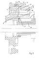
- FIG. 1 shows such a hammer brush device with a cover 1, which carries the brush device.
- Two hammer brushes 2 are each mounted on a brush pin 3.
- Each hammer brush 2 is pressed by a leg spring 10 to a commutator 18.
- the leg spring 10 is threaded onto a dome 6, which is integrally connected to the brush cover 1.
- One end of the leg spring 10 is supported in the lid 1, while the other end of the spring is provided with a hook, in which the hammer brush 2 is mounted.
- a disadvantage of this construction is that the first, the brush 2 facing turn 9 'of the leg spring 10 is pressed radially by this type of force on the dome 6 and thereby causes considerable friction. Due to the function, a small gap 19 is axially provided between the brush 2 and the dome 6, into which the first turn 9 'can slip into it. The winding then acts like a wedge and increases the friction problem. The consequence of this is a very irregular contact force of the brush 2.
- the invention has the object of providing the generic brush device in such a way that an at least substantially uniform Bürstenandruckkraft is achieved.
- the spring coil adjacent to the brush is supported radially on the support part, which is rotatably seated on the bolt.
- the support part can rotate with the brush. In this way, a relative movement between the first spring coil is avoided to their support and thereby minimized friction.
- the Bürstenandruckkraft is characterized evenly. This force is so great that there is no increased sparking and the mechanical brush wear is minimal.
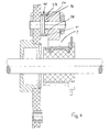
- the brush device according to FIG. 2 has the cover 1, which advantageously consists of electrically insulating plastic and is dimensionally stable. He wears distributed over its circumference hammer brushes 2, which are each limited pivotally mounted on a bolt 3.
- Fig. 2 only one of the bolts 3 is shown, which is pressed into an opening 4 passing through the lid 1.
- the opening 4 is provided in a over the back 5 of the lid 1 protruding dome 6, which is formed integrally with the lid.
- the number of bolts 3 and a corresponding number of domes 6 is distributed over the circumference of the lid provided.
- Each dome 6 is surrounded by a ring wall 7 at a distance.
- annular space 8 is formed between the dome 6 and the annular wall 7, in the turns 9 of a leg spring 10 engage.
- a thickened radial flange 13 of a socket 14 at the front side 12 of the dome 6 is a thickened radial flange 13 of a socket 14 at. It sits on the bolt 3.
- the radial flange 13 has on its hammer brush 2 side facing a circumferential radial projection 15, on which the hammer brush 2 adjacent winding 9 'of the leg spring 10 is applied.
- the flange 13 is located between the dome 6 and the end face of the hammer brush 2, which sits on the bush 14.
- the bolt 3 protrudes beyond the hammer brush 2 and has a thin head 16. It rests against the radial flange 13 opposite end face of the hammer brush 2 and secures them on the socket 14th
- leg spring 10 is hooked with a hook-shaped end in the hammer brush 2. It is thereby loaded in the direction of rotation and pressed against the commutator 18.
- the bushing 14 takes with its radial flange 13, the first, the hammer brush 2 facing turn 9 'and supports it radially.
- the radial projection 15 prevents the spring coil 9 'from slipping off the radial flange 13 in the direction of the brush 2.
- the bush 14 is rotatably mounted on the bolt 3 and thus rotates with the hammer brush 2. As a result, a relative movement of this first spring coil 9 'is avoided to its support 13, whereby the friction is significantly reduced.
- Fig. 3 shows a further embodiment, which is designed in principle the same as the embodiment of FIG. 2.
- the bolts 3 are mounted, on which the hammer brushes 2 sit.
- the bolts 3 and the hammer brushes 2 are in turn distributed over the circumference of the lid 1.
- Fig. 3 only one bolt 3 and only one hammer brush 2 is shown.
- the bolt 3 passes through the cover 1 and the hammer brush 2.
- the bolt 3 is fixedly connected to the cover 1.
- the brush 2 is rotatably mounted on the bolt 3.
- On the over the hammer brush 2 protruding end of the bolt 3, a securing member 20 is attached, which secures the brush axially.
- the bushing 14 On the side facing the cover 1 of the hammer brush 2 is the bushing 14, which has the radially outwardly projecting flange-like projection 15. In contrast to the embodiment of FIG. 2, the hammer brush 2 sits directly on the bolt. 3
- the bolt 3 carries a flange-like projection 22.
- the bushing 14 rests with its flat end face 12 against a flat end face 21 of the projection 22.
- the projection 15 prevents the first, the hammer brush 2 facing turn 9 'of the spring 10 passes into the region between the sleeve 14 and the hammer brush 2.
- the bush 14 itself is rotatable and rotates with the hammer brush 2, so that a relative movement of the first turn 9 'is avoided for its support and thus the friction is minimized.
- FIG. 4 is substantially the same design as the embodiment of FIG. 3. The difference is that the sleeve 14 has no radially outer flange, but that its outer jacket 23 is cylindrical.
- the hammer brush 2 adjacent winding 9 'of the leg spring 10 is the sleeve 14 radially projecting part of the end face 24 of the hammer brush 2 opposite.
- the gap 25 between the hammer brush 2 and the bush 14 is so small that the hammer brush 2 adjacent winding 9 'of the leg spring 10 can not slip into the gap 25.
Landscapes
- Engineering & Computer Science (AREA)
- Power Engineering (AREA)
- Motor Or Generator Current Collectors (AREA)
Abstract
Description
- Die Erfindung betrifft eine Bürsteneinrichtung, insbesondere eine Hammerbürsteneinrichtung, für einen Elektromotor nach dem Oberbegriff des Anspruches 1.
- Bürsteneinrichtungen in Form von Hammerbürsteneinrichtungen kommen bei Elektromotoren mit Kupfer-Graphit-Kommutierung zum Einsatz. Fig. 1 zeigt eine solche Hammerbürsteneinrichtung mit einem Deckel 1, der die Bürsteneinrichtung trägt. Zwei Hammerbürsten 2 sind auf je einem Bürstenbolzen 3 gelagert. Jede Hammerbürste 2 wird durch eine Schenkelfeder 10 an einen Kommutator 18 angedrückt. Die Schenkelfeder 10 ist auf einen Dom 6 aufgefädelt, der einstückig mit dem Bürstendeckel 1 verbunden ist. Ein Ende der Schenkelfeder 10 stützt sich im Deckel 1 ab, während das andere Federende mit einem Haken versehen ist, in den die Hammerbürste 2 eingehängt ist. Nachteilig an dieser Konstruktion ist, dass die erste, der Bürste 2 zugewandte Windung 9' der Schenkelfeder 10 durch diese Art der Krafteinleitung radial auf den Dom 6 gedrückt wird und dabei beträchtliche Reibung verursacht. Funktionsbedingt ist zwischen der Bürste 2 und dem Dom 6 axial ein kleiner Spalt 19 vorgesehen, in den die erste Windung 9' ein Stück weit hineinrutschen kann. Die Windung wirkt dann wie ein Keil und verstärkt das Reibungsproblem. Folge hiervon ist eine sehr unregelmäßige Anpresskraft der Bürste 2.
- Eine gleichmäßige Bürstenandruckkraft ist jedoch unabdingbar für einen guten Stromübergang zwischen der Bürste 2 und dem Kommutator 18. Ist die Kraft zu klein, kann es zu vermehrter Funkenbildung und im Extremfall zu Anlaufproblemen des Motors kommen. Ist die Kraft zu groß, ist der mechanische Bürstenverschleiß zu hoch.
- Der Erfindung liegt die Aufgabe zugrunde, die gattungsgemäße Bürsteneinrichtung so auszubilden, dass eine zumindest weitgehend gleichmäßige Bürstenandruckkraft erzielt wird.
- Diese Aufgabe wird bei der gattungsgemäßen Bürsteneinrichtung erfindungsgemäß mit den kennzeichnenden Merkmalen des Anspruches 1 gelöst.
- Bei der erfindungsgemäßen Bürsteneinrichtung stützt sich die der Bürste benachbarte Federwindung radial am Abstützteil ab, das drehbar auf dem Bolzen sitzt. Das Abstützteil kann mit der Bürste mitdrehen. Auf diese Weise wird eine Relativbewegung zwischen der ersten Federwindung zu ihrer Auflage vermieden und die Reibung dadurch minimiert. Die Bürstenandruckkraft ist dadurch gleichmäßig. Diese Kraft ist so groß, dass es zu keiner vermehrten Funkenbildung kommt und der mechanische Bürstenverschleiß minimal ist.
- Weitere Merkmale der Erfindung ergeben sich aus den weiteren Ansprüchen, der Beschreibung und den Zeichnungen.
- Die Erfindung wird anhand dreier in den Zeichnungen dargestellter Ausführungsformen näher erläutert. Es zeigen
- Fig. 1
- im Schnitt einen Teil einer Bürsteneinrichtung eines Elektromotors nach dem Stand der Technik,
- Fig. 2
- in einer Darstellung entsprechend Fig. 1 eine erfindungsgemäße Bürsteneinrichtung für einen Elektromotor,
- Fig. 3
- eine zweite Ausführungsform einer erfindungsgemäßen Bürsteneinrichtung eines Elektromotors,
- Fig. 4
- eine dritte Ausführungsform einer erfindungsgemäßen Bürsteneinrichtung eines Elektromotors.
- Die Bürsteneinrichtung gemäß Fig. 2 hat den Deckel 1, der vorteilhaft aus elektrisch isolierendem Kunststoff besteht und formsteif ausgebildet ist. Er trägt über seinen Umfang verteilt Hammerbürsten 2, die jeweils auf einem Bolzen 3 begrenzt schwenkbar gelagert sind. In Fig. 2 ist nur einer der Bolzen 3 dargestellt, der in eine den Deckel 1 durchsetzende Öffnung 4 eingepresst ist. Die Öffnung 4 ist in einem über die Rückseite 5 des Deckels 1 vorstehenden Dom 6 vorgesehen, der einstückig mit dem Deckel ausgebildet ist. Entsprechend der Zahl der Bolzen 3 ist auch eine entsprechende Zahl von Domen 6 über den Umfang des Deckels verteilt vorgesehen. Jeder Dom 6 wird mit Abstand von einer Ringwand 7 umgeben. Dadurch wird zwischen dem Dom 6 und der Ringwand 7 ein Ringraum 8 gebildet, in den Windungen 9 einer Schenkelfeder 10 eingreifen. An der Stirnseite 12 des Doms 6 liegt ein verdickter Radialflansch 13 einer Buchse 14 an. Sie sitzt auf dem Bolzen 3. Der Radialflansch 13 hat an seiner der Hammerbürste 2 zugewandten Seite einen umlaufenden radialen Vorsprung 15, an dem die der Hammerbürste 2 benachbarte Windung 9' der Schenkelfeder 10 anliegt. Der Flansch 13 liegt zwischen dem Dom 6 und der Stirnseite der Hammerbürste 2, die auf der Buchse 14 sitzt. Der Bolzen 3 ragt über die Hammerbürste 2 vor und hat einen dünnen Kopf 16. Er liegt an der dem Radialflansch 13 gegenüberliegenden Stirnseite der Hammerbürste 2 an und sichert diese auf der Buchse 14.
- Die Schenkelfeder 10 ist mit einem hakenförmigen Ende in die Hammerbürste 2 eingehängt. Sie wird dadurch in Drehrichtung belastet und gegen den Kommutator 18 gedrückt.
- Die Buchse 14 nimmt mit ihrem Radialflansch 13 die erste, der Hammerbürste 2 zugewandte Windung 9' auf und stützt diese radial ab. Der radiale Vorsprung 15 verhindert, dass die Federwindung 9' vom Radialflansch 13 in Richtung Bürste 2 abrutscht. Die Buchse 14 sitzt drehbar auf dem Bolzen 3 und dreht somit mit der Hammerbürste 2 mit. Dadurch wird eine Relativbewegung dieser ersten Federwindung 9' zu ihrer Auflage 13 vermieden, wodurch die Reibung erheblich vermindert wird.
- Aufgrund der Buchse 14 mit dem Flansch 13 wird verhindert, dass die der Hammerbürste 2 benachbarte erste Windung 9' der Schenkelfeder 10 zwischen der Hammerbürste 2 und dem Dom 6 eingeklemmt wird. Der Außendurchmesser des umlaufenden Vorsprunges 15 des Flansches 13 ist größer als der Durchmesser des Flansches 13. Die Windung 9' kann dadurch nicht zwischen den Flansch 13 und die Hammerbürste 2 gelangen. Somit ist gewährleistet, dass die Hammerbürste 2 gleichmäßig an den Kommutator 18 angedrückt wird, so dass ein guter Stromübergang zwischen der Hammerbürste 2 und dem Kommutator 18 gewährleistet ist. Der mechanische Bürstenverschleiß ist zudem gering, da infolge der drehbar auf dem Bolzen 3 gelagerten Buchse 14 sichergestellt ist, dass zwischen der der Hammerbürste 2 zugewandten ersten Windung 9' und dem Radialflansch 13 der Buchse 14 keine Reibung durch Relativbewegung auftritt.
- Fig. 3 zeigt ein weiteres Ausführungsbeispiel, das prinzipiell gleich gestaltet ist wie die Ausführungsform nach Fig. 2. Im Deckel 1 sind die Bolzen 3 gelagert, auf denen die Hammerbürsten 2 sitzen. Die Bolzen 3 und die Hammerbürsten 2 sind wiederum über den Umfang des Deckels 1 verteilt angeordnet. In Fig. 3 ist nur ein Bolzen 3 sowie nur eine Hammerbürste 2 dargestellt. Der Bolzen 3 durchsetzt den Deckel 1 sowie die Hammerbürste 2. Der Bolzen 3 ist fest mit dem Deckel 1 verbunden. Die Bürste 2 ist drehbar auf dem Bolzen 3 gelagert. Auf dem über die Hammerbürste 2 überstehenden Ende des Bolzens 3 ist ein Sicherungsteil 20 befestigt, welches die Bürste axial sichert.
- An der dem Deckel 1 zugewandten Seite der Hammerbürste 2 befindet sich die Buchse 14, die den radial nach außen ragenden flanschartigen Vorsprung 15 aufweist. Im Unterschied zur Ausführungsform nach Fig. 2 sitzt die Hammerbürste 2 unmittelbar auf dem Bolzen 3.
- Der Bolzen 3 trägt einen flanschartigen Vorsprung 22. Die Buchse 14 liegt mit ihrer ebenen Stirnseite 12 an einer ebenen Stirnseite 21 des Vorsprungs 22 an. Wie bei der Ausführungsform nach Fig. 2 verhindert der Vorsprung 15, dass die erste, der Hammerbürste 2 zugewandte Windung 9' der Feder 10 in den Bereich zwischen der Buchse 14 und der Hammerbürste 2 gelangt. Die Buchse 14 selbst ist drehbar und dreht sich mit der Hammerbürste 2 mit, so dass eine Relativbewegung der ersten Windung 9' zur ihrer Auflage vermieden und dadurch die Reibung minimiert wird.
- Das Ausführungsbeispiel gemäß Fig. 4 ist im wesentlichen gleich ausgebildet wie die Ausführungsform nach Fig. 3. Der Unterschied liegt darin, dass die Buchse 14 keinen radial äußeren Flansch hat, sondern daß ihr äußerer Mantel 23 zylindrisch ausgebildet ist. Die der Hammerbürste 2 benachbart liegende Windung 9' der Schenkelfeder 10 liegt dem die Buchse 14 radial überragenden Teil der Stirnseite 24 der Hammerbürste 2 gegenüber.
- Der Spalt 25 zwischen der Hammerbürste 2 und der Buchse 14 ist so klein, daß die der Hammerbürste 2 benachbarte Windung 9' der Schenkelfeder 10 nicht in den Spalt 25 rutschen kann.
Claims (14)
- Bürsteneinrichtung, insbesondere Hammerbürsteneinrichtung, für einen mechanisch kommutierten Elektromotor, mit mindestens einem Bolzen (3), auf dem eine Bürste (2) drehbar gelagert ist, die in Drehrichtung unter der Kraft wenigstens einer Feder (10) steht, deren Windungen (9) den Bolzen (3) umgeben,
dadurch gekennzeichnet, dass sich die der Bürste (2) benachbarte Windung (9') der Feder (10) an einem drehbar auf dem Bolzen (3) sitzenden Abstützteil (13, 14) abstützt. - Bürsteneinrichtung nach Anspruch 1,
dadurch gekennzeichnet, dass das Abstützteil (13, 14) ein radial nach außen ragender Flansch (13) einer auf dem Bolzen (3) sitzenden Buchse (14) ist. - Bürsteneinrichtung nach Anspruch 2,
dadurch gekennzeichnet, dass die Bürste (2) auf der Buchse (14) sitzt. - Bürsteneinrichtung nach Anspruch 2 oder 3,
dadurch gekennzeichnet, dass die Bürste (2) am Flansch (13) anliegt. - Bürsteneinrichtung nach einem der Ansprüche 1 bis 4,
dadurch gekennzeichnet, dass das Abstützteil (13, 14) neben der Bürste (2) liegt. - Bürsteneinrichtung nach einem der Ansprüche 1 bis 5,
dadurch gekennzeichnet, dass das Abstützteil (14) einen nach außen ragenden flanschartigen Vorsprung (15) aufweist, der verhindert, dass die Windung (9') der Feder (10) vom Abstützteil (14) axial abrutscht. - Bürsteneinrichtung nach einem der Ansprüche 1 bis 5,
dadurch gekennzeichnet, dass das Abstützteil (14) keinen nach außen ragenden flanschartigen Vorsprung (15) aufweist. - Bürsteneinrichtung nach Anspruch 7,
dadurch gekennzeichnet, dass der Spalt (25) zwischen Bürste (2) und Abstützteil (14) so klein ist, dass die Windung (9') der Feder (10) nicht in den Spalt (25) rutschen kann. - Bürsteneinrichtung nach einem der Ansprüche 1 bis 8,
dadurch gekennzeichnet, dass das Abstützteil (14) an einem von einem Deckel (1) des Elektromotors nach innen abstehenden Vorsprung (6, 22) anliegt. - Bürsteneinrichtung nach Anspruch 9,
dadurch gekennzeichnet, dass der Vorsprung (6) einstückig mit dem Deckel (1) ausgebildet ist. - Bürsteneinrichtung nach Anspruch 9,
dadurch gekennzeichnet, dass der Vorsprung (22) Teil des Bolzens (3) ist. - Bürsteneinrichtung nach Anspruch 11,
dadurch gekennzeichnet, dass der Vorsprung (22) an der Innenseite des Deckels (1) anliegt. - Bürsteneinrichtung nach Anspruch 9 oder 10,
dadurch gekennzeichnet, dass der Bolzen (3) im Vorsprung (6) befestigt ist. - Bürsteneinrichtung nach einem der Ansprüche 1 bis 12,
dadurch gekennzeichnet, dass der Bolzen (3) den Deckel (1) und die Bürste (2) durchsetzt.
Applications Claiming Priority (1)
| Application Number | Priority Date | Filing Date | Title |
|---|---|---|---|
| DE102006003101A DE102006003101A1 (de) | 2006-01-17 | 2006-01-17 | Bürsteneinrichtung, insbesondere Hammerbürsteneinrichtung, für einen Elektromotor |
Publications (3)
| Publication Number | Publication Date |
|---|---|
| EP1808942A2 true EP1808942A2 (de) | 2007-07-18 |
| EP1808942A3 EP1808942A3 (de) | 2008-05-14 |
| EP1808942B1 EP1808942B1 (de) | 2015-04-08 |
Family
ID=38042921
Family Applications (1)
| Application Number | Title | Priority Date | Filing Date |
|---|---|---|---|
| EP07000481.7A Not-in-force EP1808942B1 (de) | 2006-01-17 | 2007-01-11 | Bürsteneinrichtung, insbesondere Hammerbürsteneinrichtung, für einen Elektromotor |
Country Status (3)
| Country | Link |
|---|---|
| EP (1) | EP1808942B1 (de) |
| DE (1) | DE102006003101A1 (de) |
| HU (1) | HUE026517T2 (de) |
Cited By (3)
| Publication number | Priority date | Publication date | Assignee | Title |
|---|---|---|---|---|
| EP2600503A1 (de) * | 2011-12-02 | 2013-06-05 | Maxon Motor AG | Bürstendeckel für einen bürstenkommutierten Elektromotor und Elektromotor |
| WO2024133430A1 (de) | 2022-12-21 | 2024-06-27 | Dr. Fritz Faulhaber Gmbh & Co. Kg | Bürsteneinrichtung für einen motor und motor |
| DE202022003090U1 (de) | 2022-12-21 | 2024-10-02 | Dr. Fritz Faulhaber GmbH & Co.KG | Bürsteneinrichtung für einen Motor und Motor |
Citations (1)
| Publication number | Priority date | Publication date | Assignee | Title |
|---|---|---|---|---|
| US3851197A (en) | 1971-11-09 | 1974-11-26 | Morita Mfg | Cartridge type brush holder |
Family Cites Families (2)
| Publication number | Priority date | Publication date | Assignee | Title |
|---|---|---|---|---|
| FR1358205A (fr) * | 1963-05-31 | 1964-04-10 | Cav Ltd | Dispositif de montage de balais pour machine dynamo-électrique |
| DE2055610C3 (de) * | 1970-11-12 | 1978-05-24 | Siemens Ag, 1000 Berlin Und 8000 Muenchen | Bürstenhalteranordnung einer elektrischen Maschine |
-
2006
- 2006-01-17 DE DE102006003101A patent/DE102006003101A1/de not_active Withdrawn
-
2007
- 2007-01-11 HU HUE07000481A patent/HUE026517T2/hu unknown
- 2007-01-11 EP EP07000481.7A patent/EP1808942B1/de not_active Not-in-force
Patent Citations (1)
| Publication number | Priority date | Publication date | Assignee | Title |
|---|---|---|---|---|
| US3851197A (en) | 1971-11-09 | 1974-11-26 | Morita Mfg | Cartridge type brush holder |
Cited By (6)
| Publication number | Priority date | Publication date | Assignee | Title |
|---|---|---|---|---|
| EP2600503A1 (de) * | 2011-12-02 | 2013-06-05 | Maxon Motor AG | Bürstendeckel für einen bürstenkommutierten Elektromotor und Elektromotor |
| US9570963B2 (en) | 2011-12-02 | 2017-02-14 | Maxon Motor Ag | Brush cover for a brush-commutated electric motor and electric motor |
| WO2024133430A1 (de) | 2022-12-21 | 2024-06-27 | Dr. Fritz Faulhaber Gmbh & Co. Kg | Bürsteneinrichtung für einen motor und motor |
| DE102022134362A1 (de) | 2022-12-21 | 2024-06-27 | Dr. Fritz Faulhaber GmbH & Co.KG | Bürsteneinrichtung für einen Motor und Motor |
| DE202022003090U1 (de) | 2022-12-21 | 2024-10-02 | Dr. Fritz Faulhaber GmbH & Co.KG | Bürsteneinrichtung für einen Motor und Motor |
| DE102022134362B4 (de) * | 2022-12-21 | 2025-12-31 | Dr. Fritz Faulhaber GmbH & Co.KG | Bürsteneinrichtung für einen Motor und Motor |
Also Published As
| Publication number | Publication date |
|---|---|
| EP1808942A3 (de) | 2008-05-14 |
| HUE026517T2 (hu) | 2016-06-28 |
| EP1808942B1 (de) | 2015-04-08 |
| DE102006003101A1 (de) | 2007-07-19 |
Similar Documents
| Publication | Publication Date | Title |
|---|---|---|
| DE102016010926A1 (de) | Wellenerdungsring | |
| DE3221865A1 (de) | Lagervorrichtung fuer ein drehbares teil | |
| WO2015044034A2 (de) | Elektrische maschine und verbindungseinheit für elektrische maschine | |
| DE602005002214T2 (de) | Drehverbinder | |
| EP0500868B1 (de) | Antriebsvorrichtung, insbesondere für scheibenwischer an kraftfahrzeugen | |
| DE4227383A1 (de) | Drehbare elektrische verbindungsanordnung | |
| DE102011075653B4 (de) | Startermotor in einem Starter für eine Brennkraftmaschine | |
| DE68915104T2 (de) | Lager-Haltebrigel für dynamo-elektrischen Motor. | |
| EP1169768A1 (de) | Elektrischer antrieb, insbesondere für kraftfahrzeuge | |
| EP1808942B1 (de) | Bürsteneinrichtung, insbesondere Hammerbürsteneinrichtung, für einen Elektromotor | |
| DE102014007866B4 (de) | Kunststoffhülse zur Absicherung einer Kugelumlenkung und zur Zentrierung einer Wellfeder und einer Passscheibe in einem Lenkgetriebe | |
| WO2022043266A1 (de) | Elektromotor | |
| DE112006003971T5 (de) | Rotationsanschlussmechanismus | |
| DE10120795B4 (de) | Elektrischer Universalmotor mit Belastungseinrichtung zur Drehzahlbegrenzung | |
| DE102009027366A1 (de) | Modularer Bürstenhalter, Bausatz, elektrische Maschine sowie Hydraulikaggregat | |
| DE2840789A1 (de) | Elektromotorisch verstellbarer spiegel | |
| DE69612939T2 (de) | Schleifringanordnung für Kabeltrommel | |
| DE102007057706A1 (de) | Elektrischer Antriebsmotor, insbesondere für ein Aggragat in einem Kraftfahrzeug | |
| EP3368380B1 (de) | Schutzabdeckung für ein wickelfedergehäuse, wickelfedergehäuseanordnung und fahrzeug mit einer solchen wickelfedergehäuseanordnung | |
| EP2795743B1 (de) | Kommutatormotor | |
| DE10005568A1 (de) | Federelement zum Ausgleich von Axialspiel einer Motorwelle eines Elektromotors | |
| DE971979C (de) | Elektrische Maschine, insbesondere Kleinelektromotor, mit mindestens einem Schleifkontakt und mit einer senkrecht zur Ankerachse im Maschinengehaeuse befestigten, als Schleifkontakttraeger dienenden Isolierstoffplatte | |
| EP3079237A1 (de) | Gehäuse für einen messwertgeber oder eine elektrische maschine | |
| DE102022134362B4 (de) | Bürsteneinrichtung für einen Motor und Motor | |
| DE818819C (de) | Dynamoelektrische Maschine |
Legal Events
| Date | Code | Title | Description |
|---|---|---|---|
| PUAI | Public reference made under article 153(3) epc to a published international application that has entered the european phase |
Free format text: ORIGINAL CODE: 0009012 |
|
| AK | Designated contracting states |
Kind code of ref document: A2 Designated state(s): AT BE BG CH CY CZ DE DK EE ES FI FR GB GR HU IE IS IT LI LT LU LV MC NL PL PT RO SE SI SK TR |
|
| AX | Request for extension of the european patent |
Extension state: AL BA HR MK YU |
|
| PUAL | Search report despatched |
Free format text: ORIGINAL CODE: 0009013 |
|
| AK | Designated contracting states |
Kind code of ref document: A3 Designated state(s): AT BE BG CH CY CZ DE DK EE ES FI FR GB GR HU IE IS IT LI LT LU LV MC NL PL PT RO SE SI SK TR |
|
| AX | Request for extension of the european patent |
Extension state: AL BA HR MK RS |
|
| 17P | Request for examination filed |
Effective date: 20081105 |
|
| AKX | Designation fees paid |
Designated state(s): AT BE BG CH CY CZ DE DK EE ES FI FR GB GR HU IE IS IT LI LT LU LV MC NL PL PT RO SE SI SK TR |
|
| 17Q | First examination report despatched |
Effective date: 20120329 |
|
| RAP1 | Party data changed (applicant data changed or rights of an application transferred) |
Owner name: DR. FRITZ FAULHABER GMBH & CO. KG |
|
| GRAP | Despatch of communication of intention to grant a patent |
Free format text: ORIGINAL CODE: EPIDOSNIGR1 |
|
| RIC1 | Information provided on ipc code assigned before grant |
Ipc: H01R 39/38 20060101AFI20141124BHEP Ipc: H02K 5/14 20060101ALI20141124BHEP Ipc: H01R 39/415 20060101ALI20141124BHEP |
|
| INTG | Intention to grant announced |
Effective date: 20141209 |
|
| GRAS | Grant fee paid |
Free format text: ORIGINAL CODE: EPIDOSNIGR3 |
|
| GRAA | (expected) grant |
Free format text: ORIGINAL CODE: 0009210 |
|
| AK | Designated contracting states |
Kind code of ref document: B1 Designated state(s): AT BE BG CH CY CZ DE DK EE ES FI FR GB GR HU IE IS IT LI LT LU LV MC NL PL PT RO SE SI SK TR |
|
| REG | Reference to a national code |
Ref country code: GB Ref legal event code: FG4D Free format text: NOT ENGLISH |
|
| REG | Reference to a national code |
Ref country code: CH Ref legal event code: EP |
|
| REG | Reference to a national code |
Ref country code: CH Ref legal event code: NV Representative=s name: BRAUNPAT BRAUN EDER AG, CH |
|
| REG | Reference to a national code |
Ref country code: IE Ref legal event code: FG4D Free format text: LANGUAGE OF EP DOCUMENT: GERMAN |
|
| REG | Reference to a national code |
Ref country code: AT Ref legal event code: REF Ref document number: 721184 Country of ref document: AT Kind code of ref document: T Effective date: 20150515 |
|
| REG | Reference to a national code |
Ref country code: DE Ref legal event code: R096 Ref document number: 502007013845 Country of ref document: DE Effective date: 20150521 |
|
| REG | Reference to a national code |
Ref country code: NL Ref legal event code: VDEP Effective date: 20150408 |
|
| REG | Reference to a national code |
Ref country code: LT Ref legal event code: MG4D |
|
| PG25 | Lapsed in a contracting state [announced via postgrant information from national office to epo] |
Ref country code: NL Free format text: LAPSE BECAUSE OF FAILURE TO SUBMIT A TRANSLATION OF THE DESCRIPTION OR TO PAY THE FEE WITHIN THE PRESCRIBED TIME-LIMIT Effective date: 20150408 |
|
| PG25 | Lapsed in a contracting state [announced via postgrant information from national office to epo] |
Ref country code: ES Free format text: LAPSE BECAUSE OF FAILURE TO SUBMIT A TRANSLATION OF THE DESCRIPTION OR TO PAY THE FEE WITHIN THE PRESCRIBED TIME-LIMIT Effective date: 20150408 Ref country code: LT Free format text: LAPSE BECAUSE OF FAILURE TO SUBMIT A TRANSLATION OF THE DESCRIPTION OR TO PAY THE FEE WITHIN THE PRESCRIBED TIME-LIMIT Effective date: 20150408 Ref country code: FI Free format text: LAPSE BECAUSE OF FAILURE TO SUBMIT A TRANSLATION OF THE DESCRIPTION OR TO PAY THE FEE WITHIN THE PRESCRIBED TIME-LIMIT Effective date: 20150408 Ref country code: PT Free format text: LAPSE BECAUSE OF FAILURE TO SUBMIT A TRANSLATION OF THE DESCRIPTION OR TO PAY THE FEE WITHIN THE PRESCRIBED TIME-LIMIT Effective date: 20150810 |
|
| PG25 | Lapsed in a contracting state [announced via postgrant information from national office to epo] |
Ref country code: IS Free format text: LAPSE BECAUSE OF FAILURE TO SUBMIT A TRANSLATION OF THE DESCRIPTION OR TO PAY THE FEE WITHIN THE PRESCRIBED TIME-LIMIT Effective date: 20150808 Ref country code: GR Free format text: LAPSE BECAUSE OF FAILURE TO SUBMIT A TRANSLATION OF THE DESCRIPTION OR TO PAY THE FEE WITHIN THE PRESCRIBED TIME-LIMIT Effective date: 20150709 Ref country code: LV Free format text: LAPSE BECAUSE OF FAILURE TO SUBMIT A TRANSLATION OF THE DESCRIPTION OR TO PAY THE FEE WITHIN THE PRESCRIBED TIME-LIMIT Effective date: 20150408 |
|
| REG | Reference to a national code |
Ref country code: DE Ref legal event code: R097 Ref document number: 502007013845 Country of ref document: DE |
|
| REG | Reference to a national code |
Ref country code: FR Ref legal event code: PLFP Year of fee payment: 10 |
|
| PG25 | Lapsed in a contracting state [announced via postgrant information from national office to epo] |
Ref country code: EE Free format text: LAPSE BECAUSE OF FAILURE TO SUBMIT A TRANSLATION OF THE DESCRIPTION OR TO PAY THE FEE WITHIN THE PRESCRIBED TIME-LIMIT Effective date: 20150408 Ref country code: DK Free format text: LAPSE BECAUSE OF FAILURE TO SUBMIT A TRANSLATION OF THE DESCRIPTION OR TO PAY THE FEE WITHIN THE PRESCRIBED TIME-LIMIT Effective date: 20150408 |
|
| PLBE | No opposition filed within time limit |
Free format text: ORIGINAL CODE: 0009261 |
|
| STAA | Information on the status of an ep patent application or granted ep patent |
Free format text: STATUS: NO OPPOSITION FILED WITHIN TIME LIMIT |
|
| PG25 | Lapsed in a contracting state [announced via postgrant information from national office to epo] |
Ref country code: SK Free format text: LAPSE BECAUSE OF FAILURE TO SUBMIT A TRANSLATION OF THE DESCRIPTION OR TO PAY THE FEE WITHIN THE PRESCRIBED TIME-LIMIT Effective date: 20150408 Ref country code: PL Free format text: LAPSE BECAUSE OF FAILURE TO SUBMIT A TRANSLATION OF THE DESCRIPTION OR TO PAY THE FEE WITHIN THE PRESCRIBED TIME-LIMIT Effective date: 20150408 Ref country code: CZ Free format text: LAPSE BECAUSE OF FAILURE TO SUBMIT A TRANSLATION OF THE DESCRIPTION OR TO PAY THE FEE WITHIN THE PRESCRIBED TIME-LIMIT Effective date: 20150408 Ref country code: RO Free format text: LAPSE BECAUSE OF NON-PAYMENT OF DUE FEES Effective date: 20150408 |
|
| 26N | No opposition filed |
Effective date: 20160111 |
|
| PG25 | Lapsed in a contracting state [announced via postgrant information from national office to epo] |
Ref country code: BE Free format text: LAPSE BECAUSE OF NON-PAYMENT OF DUE FEES Effective date: 20160131 Ref country code: SI Free format text: LAPSE BECAUSE OF FAILURE TO SUBMIT A TRANSLATION OF THE DESCRIPTION OR TO PAY THE FEE WITHIN THE PRESCRIBED TIME-LIMIT Effective date: 20150408 |
|
| REG | Reference to a national code |
Ref country code: HU Ref legal event code: AG4A Ref document number: E026517 Country of ref document: HU |
|
| PG25 | Lapsed in a contracting state [announced via postgrant information from national office to epo] |
Ref country code: LU Free format text: LAPSE BECAUSE OF FAILURE TO SUBMIT A TRANSLATION OF THE DESCRIPTION OR TO PAY THE FEE WITHIN THE PRESCRIBED TIME-LIMIT Effective date: 20160111 |
|
| PG25 | Lapsed in a contracting state [announced via postgrant information from national office to epo] |
Ref country code: MC Free format text: LAPSE BECAUSE OF FAILURE TO SUBMIT A TRANSLATION OF THE DESCRIPTION OR TO PAY THE FEE WITHIN THE PRESCRIBED TIME-LIMIT Effective date: 20150408 |
|
| REG | Reference to a national code |
Ref country code: IE Ref legal event code: MM4A |
|
| REG | Reference to a national code |
Ref country code: FR Ref legal event code: PLFP Year of fee payment: 11 |
|
| PG25 | Lapsed in a contracting state [announced via postgrant information from national office to epo] |
Ref country code: IE Free format text: LAPSE BECAUSE OF NON-PAYMENT OF DUE FEES Effective date: 20160111 |
|
| PG25 | Lapsed in a contracting state [announced via postgrant information from national office to epo] |
Ref country code: SE Free format text: LAPSE BECAUSE OF FAILURE TO SUBMIT A TRANSLATION OF THE DESCRIPTION OR TO PAY THE FEE WITHIN THE PRESCRIBED TIME-LIMIT Effective date: 20150408 |
|
| REG | Reference to a national code |
Ref country code: FR Ref legal event code: PLFP Year of fee payment: 12 |
|
| REG | Reference to a national code |
Ref country code: CH Ref legal event code: PCAR Free format text: NEW ADDRESS: HOLEESTRASSE 87, 4054 BASEL (CH) |
|
| PG25 | Lapsed in a contracting state [announced via postgrant information from national office to epo] |
Ref country code: CY Free format text: LAPSE BECAUSE OF FAILURE TO SUBMIT A TRANSLATION OF THE DESCRIPTION OR TO PAY THE FEE WITHIN THE PRESCRIBED TIME-LIMIT Effective date: 20150408 |
|
| PG25 | Lapsed in a contracting state [announced via postgrant information from national office to epo] |
Ref country code: TR Free format text: LAPSE BECAUSE OF FAILURE TO SUBMIT A TRANSLATION OF THE DESCRIPTION OR TO PAY THE FEE WITHIN THE PRESCRIBED TIME-LIMIT Effective date: 20150408 |
|
| PG25 | Lapsed in a contracting state [announced via postgrant information from national office to epo] |
Ref country code: BG Free format text: LAPSE BECAUSE OF FAILURE TO SUBMIT A TRANSLATION OF THE DESCRIPTION OR TO PAY THE FEE WITHIN THE PRESCRIBED TIME-LIMIT Effective date: 20150408 |
|
| PGFP | Annual fee paid to national office [announced via postgrant information from national office to epo] |
Ref country code: FR Payment date: 20211223 Year of fee payment: 16 Ref country code: GB Payment date: 20211222 Year of fee payment: 16 |
|
| PGFP | Annual fee paid to national office [announced via postgrant information from national office to epo] |
Ref country code: CH Payment date: 20211223 Year of fee payment: 16 |
|
| PGFP | Annual fee paid to national office [announced via postgrant information from national office to epo] |
Ref country code: HU Payment date: 20220102 Year of fee payment: 16 Ref country code: DE Payment date: 20220325 Year of fee payment: 16 Ref country code: AT Payment date: 20211223 Year of fee payment: 16 |
|
| PGFP | Annual fee paid to national office [announced via postgrant information from national office to epo] |
Ref country code: IT Payment date: 20220118 Year of fee payment: 16 |
|
| P01 | Opt-out of the competence of the unified patent court (upc) registered |
Effective date: 20230526 |
|
| REG | Reference to a national code |
Ref country code: DE Ref legal event code: R119 Ref document number: 502007013845 Country of ref document: DE |
|
| REG | Reference to a national code |
Ref country code: CH Ref legal event code: PL |
|
| REG | Reference to a national code |
Ref country code: AT Ref legal event code: MM01 Ref document number: 721184 Country of ref document: AT Kind code of ref document: T Effective date: 20230111 |
|
| GBPC | Gb: european patent ceased through non-payment of renewal fee |
Effective date: 20230111 |
|
| PG25 | Lapsed in a contracting state [announced via postgrant information from national office to epo] |
Ref country code: LI Free format text: LAPSE BECAUSE OF NON-PAYMENT OF DUE FEES Effective date: 20230131 Ref country code: GB Free format text: LAPSE BECAUSE OF NON-PAYMENT OF DUE FEES Effective date: 20230111 Ref country code: DE Free format text: LAPSE BECAUSE OF NON-PAYMENT OF DUE FEES Effective date: 20230801 Ref country code: CH Free format text: LAPSE BECAUSE OF NON-PAYMENT OF DUE FEES Effective date: 20230131 Ref country code: AT Free format text: LAPSE BECAUSE OF NON-PAYMENT OF DUE FEES Effective date: 20230111 |
|
| PG25 | Lapsed in a contracting state [announced via postgrant information from national office to epo] |
Ref country code: HU Free format text: LAPSE BECAUSE OF NON-PAYMENT OF DUE FEES Effective date: 20230112 Ref country code: FR Free format text: LAPSE BECAUSE OF NON-PAYMENT OF DUE FEES Effective date: 20230131 |
|
| PG25 | Lapsed in a contracting state [announced via postgrant information from national office to epo] |
Ref country code: IT Free format text: LAPSE BECAUSE OF NON-PAYMENT OF DUE FEES Effective date: 20230111 |