EP1808942B1 - Dispositif à balais, en particulier dispositif à balais à marteau, pour moteur électrique - Google Patents
Dispositif à balais, en particulier dispositif à balais à marteau, pour moteur électrique Download PDFInfo
- Publication number
- EP1808942B1 EP1808942B1 EP07000481.7A EP07000481A EP1808942B1 EP 1808942 B1 EP1808942 B1 EP 1808942B1 EP 07000481 A EP07000481 A EP 07000481A EP 1808942 B1 EP1808942 B1 EP 1808942B1
- Authority
- EP
- European Patent Office
- Prior art keywords
- brush
- brush device
- bolt
- support part
- spring
- Prior art date
- Legal status (The legal status is an assumption and is not a legal conclusion. Google has not performed a legal analysis and makes no representation as to the accuracy of the status listed.)
- Not-in-force
Links
- 238000004804 winding Methods 0.000 description 5
- 238000010276 construction Methods 0.000 description 1
- 229910002804 graphite Inorganic materials 0.000 description 1
- 239000010439 graphite Substances 0.000 description 1
- 230000001788 irregular Effects 0.000 description 1
- 230000007704 transition Effects 0.000 description 1
Images


Classifications
-
- H—ELECTRICITY
- H01—ELECTRIC ELEMENTS
- H01R—ELECTRICALLY-CONDUCTIVE CONNECTIONS; STRUCTURAL ASSOCIATIONS OF A PLURALITY OF MUTUALLY-INSULATED ELECTRICAL CONNECTING ELEMENTS; COUPLING DEVICES; CURRENT COLLECTORS
- H01R39/00—Rotary current collectors, distributors or interrupters
- H01R39/02—Details for dynamo electric machines
- H01R39/38—Brush holders
- H01R39/385—Means for mechanical fixation of the brush holder
-
- H—ELECTRICITY
- H01—ELECTRIC ELEMENTS
- H01R—ELECTRICALLY-CONDUCTIVE CONNECTIONS; STRUCTURAL ASSOCIATIONS OF A PLURALITY OF MUTUALLY-INSULATED ELECTRICAL CONNECTING ELEMENTS; COUPLING DEVICES; CURRENT COLLECTORS
- H01R39/00—Rotary current collectors, distributors or interrupters
- H01R39/02—Details for dynamo electric machines
- H01R39/38—Brush holders
- H01R39/381—Brush holders characterised by the application of pressure to brush
-
- H—ELECTRICITY
- H01—ELECTRIC ELEMENTS
- H01R—ELECTRICALLY-CONDUCTIVE CONNECTIONS; STRUCTURAL ASSOCIATIONS OF A PLURALITY OF MUTUALLY-INSULATED ELECTRICAL CONNECTING ELEMENTS; COUPLING DEVICES; CURRENT COLLECTORS
- H01R39/00—Rotary current collectors, distributors or interrupters
- H01R39/02—Details for dynamo electric machines
- H01R39/38—Brush holders
- H01R39/41—Brush holders cartridge type
- H01R39/415—Brush holders cartridge type with self-recoiling spring
-
- H—ELECTRICITY
- H02—GENERATION; CONVERSION OR DISTRIBUTION OF ELECTRIC POWER
- H02K—DYNAMO-ELECTRIC MACHINES
- H02K5/00—Casings; Enclosures; Supports
- H02K5/04—Casings or enclosures characterised by the shape, form or construction thereof
- H02K5/14—Means for supporting or protecting brushes or brush holders
- H02K5/143—Means for supporting or protecting brushes or brush holders for cooperation with commutators
- H02K5/146—Pivotally supported brushes or brush holders
Definitions
- the invention relates to a brush device, in particular a hammer brush device, for an electric motor according to the preamble of claim 1.
- FIG. 1 shows such a hammer brush device with a cover 1, which carries the brush device.
- Two hammer brushes 2 are each mounted on a brush pin 3.
- Each hammer brush 2 is pressed by a leg spring 10 to a commutator 18.
- the leg spring 10 is threaded onto a dome 6, which is integrally connected to the brush cover 1.
- One end of the leg spring 10 is supported in the lid 1, while the other end of the spring is provided with a hook, in which the hammer brush 2 is mounted.
- a disadvantage of this construction is that the first, the brush 2 facing turn 9 'of the leg spring 10 is pressed radially by this type of force on the dome 6 and thereby causes considerable friction. Due to the function, a small gap 19 is axially provided between the brush 2 and the dome 6, into which the first turn 9 'can slip into it. The winding then acts like a wedge and increases the friction problem. The consequence of this is a very irregular contact force of the brush 2.
- a brush device for a micromotor for dental equipment in which the brush device is supported by a lid.
- Each brush is fastened by means of a holding arm on a movable sleeve acting as a supporting part of a spring and mounted on a brush bolt by means of the sleeve.
- the brush pins are mounted in the lid.
- the spring surrounds the sleeve and is attached to one side with the lid and attached to the other side with the brush holder and presses the brush over the support arm in the direction of a commutator of a motor.
- a friction arises between the turns of the spring and the sleeve, in particular in the region of the spring adjacent to the cover.
- the invention has the object of providing the generic brush device in such a way that an at least substantially uniform Bürstenandruckkraft is achieved.
- the spring coil adjacent to the brush is supported radially on the support part, which is rotatably seated on the bolt.
- the support part rotates with the brush. In this way, a relative movement between the first spring coil is avoided to their support and thereby minimized friction.
- the Bürstenandruckkraft is characterized evenly. This force is so great that there is no increased sparking and the mechanical brush wear is minimal.
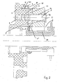
- the brush device according to Fig. 2 has the lid 1, which is advantageously made of electrically insulating plastic and is dimensionally stable. He wears distributed over its circumference hammer brushes 2, which are each limited pivotally mounted on a bolt 3.
- Fig. 2 only one of the bolts 3 is shown, which is pressed into an opening 4 passing through the cover 1.
- the opening 4 is provided in a over the back 5 of the lid 1 protruding dome 6, which is formed integrally with the lid.
- the number of bolts 3 and a corresponding number of domes 6 is distributed over the circumference of the lid provided. Each dome 6 is surrounded by a ring wall 7 at a distance.
- annular space 8 is formed between the dome 6 and the annular wall 7, in the turns 9 of a leg spring 10 engage.
- a thickened radial flange 13 of a socket 14 at the front side 12 of the dome 6 is a thickened radial flange 13 of a socket 14 at. It sits on the bolt 3.
- the radial flange 13 has on its the hammer brush 2 side facing a circumferential radial projection 15 on which the hammer brush 2 adjacent winding 9 'of the leg spring 10 is applied.
- the flange 13 is located between the dome 6 and the end face of the hammer brush 2, which sits on the bush 14.
- the bolt 3 protrudes beyond the hammer brush 2 and has a thin head 16. It rests against the radial flange 13 opposite end face of the hammer brush 2 and secures them on the socket 14th
- leg spring 10 is hooked with a hook-shaped end in the hammer brush 2. It is thereby loaded in the direction of rotation and pressed against the commutator 18.
- the bushing 14 takes with its radial flange 13, the first, the hammer brush 2 facing turn 9 'and supports it radially.
- the radial projection 15 prevents the spring coil 9 'from slipping off the radial flange 13 in the direction of the brush 2.
- the bush 14 is rotatably mounted on the bolt 3 and thus rotates with the hammer brush 2. As a result, a relative movement of this first spring coil 9 'is avoided to its support 13, whereby the friction is significantly reduced.
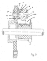
- Fig. 3 shows a further embodiment, which is designed in principle the same as the embodiment according to Fig. 2 ,
- the bolts 3 are mounted, on which the hammer brushes 2 sit.
- the bolts 3 and the hammer brushes 2 are in turn distributed over the circumference of the lid 1.
- Fig. 3 only one bolt 3 and only one hammer brush 2 is shown.
- the bolt 3 passes through the cover 1 and the hammer brush 2.
- the bolt 3 is fixedly connected to the cover 1.
- the brush 2 is rotatably mounted on the bolt 3.
- On the over the hammer brush 2 protruding end of the bolt 3, a securing member 20 is attached, which secures the brush axially.
- the bushing 14 On the side facing the cover 1 of the hammer brush 2 is the bushing 14, which has the radially outwardly projecting flange-like projection 15. In contrast to the embodiment according to Fig. 2 the hammer brush 2 sits directly on the bolt 3.
- the bolt 3 carries a flange-like projection 22.
- the bushing 14 rests with its flat end face 12 against a flat end face 21 of the projection 22.
- the bush 14 itself is rotatable and rotates with the hammer brush 2, so that a relative movement of the first turn 9 'is avoided for its support and thus the friction is minimized.
- the embodiment according to Fig. 4 is substantially the same design as the embodiment according to Fig. 3 , The difference is that the sleeve 14 has no radially outer flange, but that its outer jacket 23 is cylindrical.
- the hammer brush 2 adjacent winding 9 'of the leg spring 10 is the sleeve 14 radially projecting part of the end face 24 of the hammer brush 2 opposite.
- the gap 25 between the hammer brush 2 and the bush 14 is so small that the hammer brush 2 adjacent winding 9 'of the leg spring 10 can not slip into the gap 25.
Landscapes
- Engineering & Computer Science (AREA)
- Power Engineering (AREA)
- Motor Or Generator Current Collectors (AREA)
Claims (14)
- Dispositif à balais, en particulier dispositif à balais à marteau, pour un moteur électrique à commutation mécanique, comprenant au moins un axe (3), sur lequel est monté tournant un balai (2), soumis dans le sens de rotation à une force d'au moins un ressort (10) dont les spires (9) entourent l'axe (3), dispositif dans lequel la spire (9') du ressort (10), voisine du balai (2), s'appuie sur une pièce support (13, 14), qui repose en rotation sur l'axe (3) et tourne avec le balai (2),
caractérisé en ce que les spires (9) du ressort (10) entourent un dôme (6), réalisé d'une seule pièce avec un couvercle (1), ou une saillie (22), réalisée sous forme de partie de l'axe (3). - Dispositif à balais selon la revendication 1,
caractérisé en ce que la pièce support (13, 14) est une bride (13), qui dépasse vers l'extérieur dans la direction radiale, d'une douille (14) qui repose sur l'axe (3). - Dispositif à balais selon la revendication 2,
caractérisé en ce que le balai (2) repose sur la douille (14). - Dispositif à balais selon l'une des revendications 2 et 3,
caractérisé en ce que le balai (2) s'applique sur la bride (13). - Dispositif à balais selon l'une des revendications 1 à 4,
caractérisé en ce que la pièce support (13, 14) se situe à côté du balai (2). - Dispositif à balais selon l'une des revendications 1 à 5,
caractérisé en ce que la pièce support (13, 14) présente une saillie (15) en forme de bride, qui dépasse vers l'extérieur et empêche que la spire (9') du ressort (10) glisse de la pièce support (13, 14) dans la direction axiale. - Dispositif à balais selon l'une des revendications 1 à 6,
caractérisé en ce que la pièce support (13, 14) ne présente aucune saillie (15) en forme de bride dépassant vers l'extérieur. - Dispositif à balais selon la revendication 7,
caractérisé en ce que la fente (25) entre le balai (2) et la pièce support (13, 14) est si petite que la spire (9') du ressort (10) ne peut pas glisser dans la fente (25). - Dispositif à balais selon l'une des revendications 1 à 8,
caractérisé en ce que la pièce support (13, 14) s'applique sur le dôme (6) ou la saillie (22), qui dépassent vers l'intérieur du couvercle (1) du moteur électrique. - Dispositif à balais selon l'une des revendications 1 à 9,
caractérisé en ce que la saillie (22) s'applique sur le côté intérieur du couvercle (1). - Dispositif à balais selon l'une des revendications 1 à 10,
caractérisé en ce que l'axe (3) est fixé dans le dôme (6). - Dispositif à balais selon l'une des revendications 1 à 11,
caractérisé en ce que l'axe (3) traverse le couvercle (1) et le balai (2). - Dispositif à balais selon l'une des revendications 1 à 12,
caractérisé en ce que le dôme (6) est entouré à distance par une paroi annulaire (7) et un espace annulaire (8) est formé de ce fait. - Dispositif à balais selon la revendication 13,
caractérisé en ce que les spires (9) du ressort à branches (10) s'engagent dans l'espace annulaire (8).
Applications Claiming Priority (1)
| Application Number | Priority Date | Filing Date | Title |
|---|---|---|---|
| DE102006003101A DE102006003101A1 (de) | 2006-01-17 | 2006-01-17 | Bürsteneinrichtung, insbesondere Hammerbürsteneinrichtung, für einen Elektromotor |
Publications (3)
| Publication Number | Publication Date |
|---|---|
| EP1808942A2 EP1808942A2 (fr) | 2007-07-18 |
| EP1808942A3 EP1808942A3 (fr) | 2008-05-14 |
| EP1808942B1 true EP1808942B1 (fr) | 2015-04-08 |
Family
ID=38042921
Family Applications (1)
| Application Number | Title | Priority Date | Filing Date |
|---|---|---|---|
| EP07000481.7A Not-in-force EP1808942B1 (fr) | 2006-01-17 | 2007-01-11 | Dispositif à balais, en particulier dispositif à balais à marteau, pour moteur électrique |
Country Status (3)
| Country | Link |
|---|---|
| EP (1) | EP1808942B1 (fr) |
| DE (1) | DE102006003101A1 (fr) |
| HU (1) | HUE026517T2 (fr) |
Families Citing this family (3)
| Publication number | Priority date | Publication date | Assignee | Title |
|---|---|---|---|---|
| EP2600503B1 (fr) | 2011-12-02 | 2019-02-13 | Lakeview Innovation Ltd. | Couvercle pour balais destiné à un moteur électrique à collecteur et moteur électrique |
| DE102022134362B4 (de) | 2022-12-21 | 2025-12-31 | Dr. Fritz Faulhaber GmbH & Co.KG | Bürsteneinrichtung für einen Motor und Motor |
| DE202022003090U1 (de) | 2022-12-21 | 2024-10-02 | Dr. Fritz Faulhaber GmbH & Co.KG | Bürsteneinrichtung für einen Motor und Motor |
Family Cites Families (3)
| Publication number | Priority date | Publication date | Assignee | Title |
|---|---|---|---|---|
| FR1358205A (fr) * | 1963-05-31 | 1964-04-10 | Cav Ltd | Dispositif de montage de balais pour machine dynamo-électrique |
| DE2055610C3 (de) * | 1970-11-12 | 1978-05-24 | Siemens Ag, 1000 Berlin Und 8000 Muenchen | Bürstenhalteranordnung einer elektrischen Maschine |
| JPS4860398U (fr) * | 1971-11-09 | 1973-08-01 |
-
2006
- 2006-01-17 DE DE102006003101A patent/DE102006003101A1/de not_active Withdrawn
-
2007
- 2007-01-11 HU HUE07000481A patent/HUE026517T2/hu unknown
- 2007-01-11 EP EP07000481.7A patent/EP1808942B1/fr not_active Not-in-force
Also Published As
| Publication number | Publication date |
|---|---|
| EP1808942A3 (fr) | 2008-05-14 |
| HUE026517T2 (hu) | 2016-06-28 |
| EP1808942A2 (fr) | 2007-07-18 |
| DE102006003101A1 (de) | 2007-07-19 |
Similar Documents
| Publication | Publication Date | Title |
|---|---|---|
| DE102016010926A1 (de) | Wellenerdungsring | |
| DE102020130944A1 (de) | Isoliervorrichtung für ein Lager | |
| WO2015044034A2 (fr) | Machine électrique et unité de raccordement pour machine électrique | |
| DE3221865A1 (de) | Lagervorrichtung fuer ein drehbares teil | |
| DE602005002214T2 (de) | Drehverbinder | |
| DE4227383A1 (de) | Drehbare elektrische verbindungsanordnung | |
| EP1808942B1 (fr) | Dispositif à balais, en particulier dispositif à balais à marteau, pour moteur électrique | |
| EP1722459A1 (fr) | Machine électrique avec dispositif pour soutenir le rotor sur le partie frontal du stator | |
| WO2022043266A1 (fr) | Moteur électrique | |
| DE102018216966A1 (de) | Elektromotor mit geerdeter Welle | |
| DE102009027366A1 (de) | Modularer Bürstenhalter, Bausatz, elektrische Maschine sowie Hydraulikaggregat | |
| DE10120795B4 (de) | Elektrischer Universalmotor mit Belastungseinrichtung zur Drehzahlbegrenzung | |
| EP2750269B1 (fr) | Groupe motopompe | |
| DE69612939T2 (de) | Schleifringanordnung für Kabeltrommel | |
| EP3368380B1 (fr) | Protection pour cassette de câble spiral, ensemble de cassette de câble spiral et véhicule avec un tel ensemble | |
| DE102022002717A1 (de) | Elektromotor mit Bremsanordnung | |
| DE69601806T2 (de) | Elektrische drehende Maschine mit verbesserten Verbindungs- und Dichtungsmitteln | |
| EP2795743B1 (fr) | Moteur à commutateur | |
| DE102017214853A1 (de) | Motor und Motormontagevorrichtung | |
| EP3079237A1 (fr) | Tour pour un dispositif d'établissement de valeurs de mesure ou une machine électrique | |
| DE102022134362B4 (de) | Bürsteneinrichtung für einen Motor und Motor | |
| DE102004058349B3 (de) | Transportsicherung für eine elektrische Maschine sowie elektrische Maschine | |
| DE202022003090U1 (de) | Bürsteneinrichtung für einen Motor und Motor | |
| DE102023134102B4 (de) | Stromableitelement | |
| DE10250142B4 (de) | Masseschlussfester Gleichstromelektromotor |
Legal Events
| Date | Code | Title | Description |
|---|---|---|---|
| PUAI | Public reference made under article 153(3) epc to a published international application that has entered the european phase |
Free format text: ORIGINAL CODE: 0009012 |
|
| AK | Designated contracting states |
Kind code of ref document: A2 Designated state(s): AT BE BG CH CY CZ DE DK EE ES FI FR GB GR HU IE IS IT LI LT LU LV MC NL PL PT RO SE SI SK TR |
|
| AX | Request for extension of the european patent |
Extension state: AL BA HR MK YU |
|
| PUAL | Search report despatched |
Free format text: ORIGINAL CODE: 0009013 |
|
| AK | Designated contracting states |
Kind code of ref document: A3 Designated state(s): AT BE BG CH CY CZ DE DK EE ES FI FR GB GR HU IE IS IT LI LT LU LV MC NL PL PT RO SE SI SK TR |
|
| AX | Request for extension of the european patent |
Extension state: AL BA HR MK RS |
|
| 17P | Request for examination filed |
Effective date: 20081105 |
|
| AKX | Designation fees paid |
Designated state(s): AT BE BG CH CY CZ DE DK EE ES FI FR GB GR HU IE IS IT LI LT LU LV MC NL PL PT RO SE SI SK TR |
|
| 17Q | First examination report despatched |
Effective date: 20120329 |
|
| RAP1 | Party data changed (applicant data changed or rights of an application transferred) |
Owner name: DR. FRITZ FAULHABER GMBH & CO. KG |
|
| GRAP | Despatch of communication of intention to grant a patent |
Free format text: ORIGINAL CODE: EPIDOSNIGR1 |
|
| RIC1 | Information provided on ipc code assigned before grant |
Ipc: H01R 39/38 20060101AFI20141124BHEP Ipc: H02K 5/14 20060101ALI20141124BHEP Ipc: H01R 39/415 20060101ALI20141124BHEP |
|
| INTG | Intention to grant announced |
Effective date: 20141209 |
|
| GRAS | Grant fee paid |
Free format text: ORIGINAL CODE: EPIDOSNIGR3 |
|
| GRAA | (expected) grant |
Free format text: ORIGINAL CODE: 0009210 |
|
| AK | Designated contracting states |
Kind code of ref document: B1 Designated state(s): AT BE BG CH CY CZ DE DK EE ES FI FR GB GR HU IE IS IT LI LT LU LV MC NL PL PT RO SE SI SK TR |
|
| REG | Reference to a national code |
Ref country code: GB Ref legal event code: FG4D Free format text: NOT ENGLISH |
|
| REG | Reference to a national code |
Ref country code: CH Ref legal event code: EP |
|
| REG | Reference to a national code |
Ref country code: CH Ref legal event code: NV Representative=s name: BRAUNPAT BRAUN EDER AG, CH |
|
| REG | Reference to a national code |
Ref country code: IE Ref legal event code: FG4D Free format text: LANGUAGE OF EP DOCUMENT: GERMAN |
|
| REG | Reference to a national code |
Ref country code: AT Ref legal event code: REF Ref document number: 721184 Country of ref document: AT Kind code of ref document: T Effective date: 20150515 |
|
| REG | Reference to a national code |
Ref country code: DE Ref legal event code: R096 Ref document number: 502007013845 Country of ref document: DE Effective date: 20150521 |
|
| REG | Reference to a national code |
Ref country code: NL Ref legal event code: VDEP Effective date: 20150408 |
|
| REG | Reference to a national code |
Ref country code: LT Ref legal event code: MG4D |
|
| PG25 | Lapsed in a contracting state [announced via postgrant information from national office to epo] |
Ref country code: NL Free format text: LAPSE BECAUSE OF FAILURE TO SUBMIT A TRANSLATION OF THE DESCRIPTION OR TO PAY THE FEE WITHIN THE PRESCRIBED TIME-LIMIT Effective date: 20150408 |
|
| PG25 | Lapsed in a contracting state [announced via postgrant information from national office to epo] |
Ref country code: ES Free format text: LAPSE BECAUSE OF FAILURE TO SUBMIT A TRANSLATION OF THE DESCRIPTION OR TO PAY THE FEE WITHIN THE PRESCRIBED TIME-LIMIT Effective date: 20150408 Ref country code: LT Free format text: LAPSE BECAUSE OF FAILURE TO SUBMIT A TRANSLATION OF THE DESCRIPTION OR TO PAY THE FEE WITHIN THE PRESCRIBED TIME-LIMIT Effective date: 20150408 Ref country code: FI Free format text: LAPSE BECAUSE OF FAILURE TO SUBMIT A TRANSLATION OF THE DESCRIPTION OR TO PAY THE FEE WITHIN THE PRESCRIBED TIME-LIMIT Effective date: 20150408 Ref country code: PT Free format text: LAPSE BECAUSE OF FAILURE TO SUBMIT A TRANSLATION OF THE DESCRIPTION OR TO PAY THE FEE WITHIN THE PRESCRIBED TIME-LIMIT Effective date: 20150810 |
|
| PG25 | Lapsed in a contracting state [announced via postgrant information from national office to epo] |
Ref country code: IS Free format text: LAPSE BECAUSE OF FAILURE TO SUBMIT A TRANSLATION OF THE DESCRIPTION OR TO PAY THE FEE WITHIN THE PRESCRIBED TIME-LIMIT Effective date: 20150808 Ref country code: GR Free format text: LAPSE BECAUSE OF FAILURE TO SUBMIT A TRANSLATION OF THE DESCRIPTION OR TO PAY THE FEE WITHIN THE PRESCRIBED TIME-LIMIT Effective date: 20150709 Ref country code: LV Free format text: LAPSE BECAUSE OF FAILURE TO SUBMIT A TRANSLATION OF THE DESCRIPTION OR TO PAY THE FEE WITHIN THE PRESCRIBED TIME-LIMIT Effective date: 20150408 |
|
| REG | Reference to a national code |
Ref country code: DE Ref legal event code: R097 Ref document number: 502007013845 Country of ref document: DE |
|
| REG | Reference to a national code |
Ref country code: FR Ref legal event code: PLFP Year of fee payment: 10 |
|
| PG25 | Lapsed in a contracting state [announced via postgrant information from national office to epo] |
Ref country code: EE Free format text: LAPSE BECAUSE OF FAILURE TO SUBMIT A TRANSLATION OF THE DESCRIPTION OR TO PAY THE FEE WITHIN THE PRESCRIBED TIME-LIMIT Effective date: 20150408 Ref country code: DK Free format text: LAPSE BECAUSE OF FAILURE TO SUBMIT A TRANSLATION OF THE DESCRIPTION OR TO PAY THE FEE WITHIN THE PRESCRIBED TIME-LIMIT Effective date: 20150408 |
|
| PLBE | No opposition filed within time limit |
Free format text: ORIGINAL CODE: 0009261 |
|
| STAA | Information on the status of an ep patent application or granted ep patent |
Free format text: STATUS: NO OPPOSITION FILED WITHIN TIME LIMIT |
|
| PG25 | Lapsed in a contracting state [announced via postgrant information from national office to epo] |
Ref country code: SK Free format text: LAPSE BECAUSE OF FAILURE TO SUBMIT A TRANSLATION OF THE DESCRIPTION OR TO PAY THE FEE WITHIN THE PRESCRIBED TIME-LIMIT Effective date: 20150408 Ref country code: PL Free format text: LAPSE BECAUSE OF FAILURE TO SUBMIT A TRANSLATION OF THE DESCRIPTION OR TO PAY THE FEE WITHIN THE PRESCRIBED TIME-LIMIT Effective date: 20150408 Ref country code: CZ Free format text: LAPSE BECAUSE OF FAILURE TO SUBMIT A TRANSLATION OF THE DESCRIPTION OR TO PAY THE FEE WITHIN THE PRESCRIBED TIME-LIMIT Effective date: 20150408 Ref country code: RO Free format text: LAPSE BECAUSE OF NON-PAYMENT OF DUE FEES Effective date: 20150408 |
|
| 26N | No opposition filed |
Effective date: 20160111 |
|
| PG25 | Lapsed in a contracting state [announced via postgrant information from national office to epo] |
Ref country code: BE Free format text: LAPSE BECAUSE OF NON-PAYMENT OF DUE FEES Effective date: 20160131 Ref country code: SI Free format text: LAPSE BECAUSE OF FAILURE TO SUBMIT A TRANSLATION OF THE DESCRIPTION OR TO PAY THE FEE WITHIN THE PRESCRIBED TIME-LIMIT Effective date: 20150408 |
|
| REG | Reference to a national code |
Ref country code: HU Ref legal event code: AG4A Ref document number: E026517 Country of ref document: HU |
|
| PG25 | Lapsed in a contracting state [announced via postgrant information from national office to epo] |
Ref country code: LU Free format text: LAPSE BECAUSE OF FAILURE TO SUBMIT A TRANSLATION OF THE DESCRIPTION OR TO PAY THE FEE WITHIN THE PRESCRIBED TIME-LIMIT Effective date: 20160111 |
|
| PG25 | Lapsed in a contracting state [announced via postgrant information from national office to epo] |
Ref country code: MC Free format text: LAPSE BECAUSE OF FAILURE TO SUBMIT A TRANSLATION OF THE DESCRIPTION OR TO PAY THE FEE WITHIN THE PRESCRIBED TIME-LIMIT Effective date: 20150408 |
|
| REG | Reference to a national code |
Ref country code: IE Ref legal event code: MM4A |
|
| REG | Reference to a national code |
Ref country code: FR Ref legal event code: PLFP Year of fee payment: 11 |
|
| PG25 | Lapsed in a contracting state [announced via postgrant information from national office to epo] |
Ref country code: IE Free format text: LAPSE BECAUSE OF NON-PAYMENT OF DUE FEES Effective date: 20160111 |
|
| PG25 | Lapsed in a contracting state [announced via postgrant information from national office to epo] |
Ref country code: SE Free format text: LAPSE BECAUSE OF FAILURE TO SUBMIT A TRANSLATION OF THE DESCRIPTION OR TO PAY THE FEE WITHIN THE PRESCRIBED TIME-LIMIT Effective date: 20150408 |
|
| REG | Reference to a national code |
Ref country code: FR Ref legal event code: PLFP Year of fee payment: 12 |
|
| REG | Reference to a national code |
Ref country code: CH Ref legal event code: PCAR Free format text: NEW ADDRESS: HOLEESTRASSE 87, 4054 BASEL (CH) |
|
| PG25 | Lapsed in a contracting state [announced via postgrant information from national office to epo] |
Ref country code: CY Free format text: LAPSE BECAUSE OF FAILURE TO SUBMIT A TRANSLATION OF THE DESCRIPTION OR TO PAY THE FEE WITHIN THE PRESCRIBED TIME-LIMIT Effective date: 20150408 |
|
| PG25 | Lapsed in a contracting state [announced via postgrant information from national office to epo] |
Ref country code: TR Free format text: LAPSE BECAUSE OF FAILURE TO SUBMIT A TRANSLATION OF THE DESCRIPTION OR TO PAY THE FEE WITHIN THE PRESCRIBED TIME-LIMIT Effective date: 20150408 |
|
| PG25 | Lapsed in a contracting state [announced via postgrant information from national office to epo] |
Ref country code: BG Free format text: LAPSE BECAUSE OF FAILURE TO SUBMIT A TRANSLATION OF THE DESCRIPTION OR TO PAY THE FEE WITHIN THE PRESCRIBED TIME-LIMIT Effective date: 20150408 |
|
| PGFP | Annual fee paid to national office [announced via postgrant information from national office to epo] |
Ref country code: FR Payment date: 20211223 Year of fee payment: 16 Ref country code: GB Payment date: 20211222 Year of fee payment: 16 |
|
| PGFP | Annual fee paid to national office [announced via postgrant information from national office to epo] |
Ref country code: CH Payment date: 20211223 Year of fee payment: 16 |
|
| PGFP | Annual fee paid to national office [announced via postgrant information from national office to epo] |
Ref country code: HU Payment date: 20220102 Year of fee payment: 16 Ref country code: DE Payment date: 20220325 Year of fee payment: 16 Ref country code: AT Payment date: 20211223 Year of fee payment: 16 |
|
| PGFP | Annual fee paid to national office [announced via postgrant information from national office to epo] |
Ref country code: IT Payment date: 20220118 Year of fee payment: 16 |
|
| P01 | Opt-out of the competence of the unified patent court (upc) registered |
Effective date: 20230526 |
|
| REG | Reference to a national code |
Ref country code: DE Ref legal event code: R119 Ref document number: 502007013845 Country of ref document: DE |
|
| REG | Reference to a national code |
Ref country code: CH Ref legal event code: PL |
|
| REG | Reference to a national code |
Ref country code: AT Ref legal event code: MM01 Ref document number: 721184 Country of ref document: AT Kind code of ref document: T Effective date: 20230111 |
|
| GBPC | Gb: european patent ceased through non-payment of renewal fee |
Effective date: 20230111 |
|
| PG25 | Lapsed in a contracting state [announced via postgrant information from national office to epo] |
Ref country code: LI Free format text: LAPSE BECAUSE OF NON-PAYMENT OF DUE FEES Effective date: 20230131 Ref country code: GB Free format text: LAPSE BECAUSE OF NON-PAYMENT OF DUE FEES Effective date: 20230111 Ref country code: DE Free format text: LAPSE BECAUSE OF NON-PAYMENT OF DUE FEES Effective date: 20230801 Ref country code: CH Free format text: LAPSE BECAUSE OF NON-PAYMENT OF DUE FEES Effective date: 20230131 Ref country code: AT Free format text: LAPSE BECAUSE OF NON-PAYMENT OF DUE FEES Effective date: 20230111 |
|
| PG25 | Lapsed in a contracting state [announced via postgrant information from national office to epo] |
Ref country code: HU Free format text: LAPSE BECAUSE OF NON-PAYMENT OF DUE FEES Effective date: 20230112 Ref country code: FR Free format text: LAPSE BECAUSE OF NON-PAYMENT OF DUE FEES Effective date: 20230131 |
|
| PG25 | Lapsed in a contracting state [announced via postgrant information from national office to epo] |
Ref country code: IT Free format text: LAPSE BECAUSE OF NON-PAYMENT OF DUE FEES Effective date: 20230111 |