EP1808967A1 - Méthode pour l'alignement de codes pour le traitement de signaux DSSS - Google Patents
Méthode pour l'alignement de codes pour le traitement de signaux DSSS Download PDFInfo
- Publication number
- EP1808967A1 EP1808967A1 EP07100502A EP07100502A EP1808967A1 EP 1808967 A1 EP1808967 A1 EP 1808967A1 EP 07100502 A EP07100502 A EP 07100502A EP 07100502 A EP07100502 A EP 07100502A EP 1808967 A1 EP1808967 A1 EP 1808967A1
- Authority
- EP
- European Patent Office
- Prior art keywords
- chip
- code
- local reference
- signal
- reference code
- Prior art date
- Legal status (The legal status is an assumption and is not a legal conclusion. Google has not performed a legal analysis and makes no representation as to the accuracy of the status listed.)
- Withdrawn
Links
- 238000012545 processing Methods 0.000 title claims abstract description 32
- 238000000034 method Methods 0.000 title claims abstract description 24
- 230000002123 temporal effect Effects 0.000 claims abstract description 12
- 238000001228 spectrum Methods 0.000 claims abstract description 11
- 230000003111 delayed effect Effects 0.000 claims description 11
- 230000006870 function Effects 0.000 description 26
- 238000011084 recovery Methods 0.000 description 22
- 230000004044 response Effects 0.000 description 19
- 230000014509 gene expression Effects 0.000 description 12
- 239000010931 gold Substances 0.000 description 10
- 229910052737 gold Inorganic materials 0.000 description 10
- PCHJSUWPFVWCPO-UHFFFAOYSA-N gold Chemical compound [Au] PCHJSUWPFVWCPO-UHFFFAOYSA-N 0.000 description 9
- 238000005070 sampling Methods 0.000 description 7
- 238000010586 diagram Methods 0.000 description 6
- 230000008569 process Effects 0.000 description 6
- 238000004590 computer program Methods 0.000 description 4
- 230000002596 correlated effect Effects 0.000 description 4
- 238000007792 addition Methods 0.000 description 3
- 230000000875 corresponding effect Effects 0.000 description 3
- 238000000926 separation method Methods 0.000 description 3
- 230000008859 change Effects 0.000 description 2
- 238000004364 calculation method Methods 0.000 description 1
- 238000006243 chemical reaction Methods 0.000 description 1
- 238000004891 communication Methods 0.000 description 1
- 238000012937 correction Methods 0.000 description 1
- 230000007423 decrease Effects 0.000 description 1
- 239000006185 dispersion Substances 0.000 description 1
- 230000000694 effects Effects 0.000 description 1
- 238000005562 fading Methods 0.000 description 1
- 239000005433 ionosphere Substances 0.000 description 1
- 238000012986 modification Methods 0.000 description 1
- 230000004048 modification Effects 0.000 description 1
- 230000003287 optical effect Effects 0.000 description 1
- 238000005316 response function Methods 0.000 description 1
- 230000002441 reversible effect Effects 0.000 description 1
Images



Classifications
-
- H—ELECTRICITY
- H04—ELECTRIC COMMUNICATION TECHNIQUE
- H04B—TRANSMISSION
- H04B1/00—Details of transmission systems, not covered by a single one of groups H04B3/00 - H04B13/00; Details of transmission systems not characterised by the medium used for transmission
- H04B1/69—Spread spectrum techniques
- H04B1/707—Spread spectrum techniques using direct sequence modulation
- H04B1/7073—Synchronisation aspects
- H04B1/7075—Synchronisation aspects with code phase acquisition
- H04B1/70757—Synchronisation aspects with code phase acquisition with increased resolution, i.e. higher than half a chip
-
- G—PHYSICS
- G01—MEASURING; TESTING
- G01S—RADIO DIRECTION-FINDING; RADIO NAVIGATION; DETERMINING DISTANCE OR VELOCITY BY USE OF RADIO WAVES; LOCATING OR PRESENCE-DETECTING BY USE OF THE REFLECTION OR RERADIATION OF RADIO WAVES; ANALOGOUS ARRANGEMENTS USING OTHER WAVES
- G01S19/00—Satellite radio beacon positioning systems; Determining position, velocity or attitude using signals transmitted by such systems
- G01S19/01—Satellite radio beacon positioning systems transmitting time-stamped messages, e.g. GPS [Global Positioning System], GLONASS [Global Orbiting Navigation Satellite System] or GALILEO
- G01S19/13—Receivers
- G01S19/24—Acquisition or tracking or demodulation of signals transmitted by the system
- G01S19/30—Acquisition or tracking or demodulation of signals transmitted by the system code related
-
- H—ELECTRICITY
- H04—ELECTRIC COMMUNICATION TECHNIQUE
- H04B—TRANSMISSION
- H04B1/00—Details of transmission systems, not covered by a single one of groups H04B3/00 - H04B13/00; Details of transmission systems not characterised by the medium used for transmission
- H04B1/69—Spread spectrum techniques
- H04B1/707—Spread spectrum techniques using direct sequence modulation
- H04B1/7073—Synchronisation aspects
- H04B1/7075—Synchronisation aspects with code phase acquisition
- H04B1/7077—Multi-step acquisition, e.g. multi-dwell, coarse-fine or validation
- H04B1/70775—Multi-dwell schemes, i.e. multiple accumulation times
-
- H—ELECTRICITY
- H04—ELECTRIC COMMUNICATION TECHNIQUE
- H04B—TRANSMISSION
- H04B1/00—Details of transmission systems, not covered by a single one of groups H04B3/00 - H04B13/00; Details of transmission systems not characterised by the medium used for transmission
- H04B1/69—Spread spectrum techniques
- H04B1/707—Spread spectrum techniques using direct sequence modulation
- H04B1/7073—Synchronisation aspects
- H04B1/7075—Synchronisation aspects with code phase acquisition
- H04B1/7077—Multi-step acquisition, e.g. multi-dwell, coarse-fine or validation
-
- H—ELECTRICITY
- H04—ELECTRIC COMMUNICATION TECHNIQUE
- H04B—TRANSMISSION
- H04B1/00—Details of transmission systems, not covered by a single one of groups H04B3/00 - H04B13/00; Details of transmission systems not characterised by the medium used for transmission
- H04B1/69—Spread spectrum techniques
- H04B1/707—Spread spectrum techniques using direct sequence modulation
- H04B2001/70706—Spread spectrum techniques using direct sequence modulation using a code tracking loop, e.g. a delay locked loop
-
- H—ELECTRICITY
- H04—ELECTRIC COMMUNICATION TECHNIQUE
- H04B—TRANSMISSION
- H04B2201/00—Indexing scheme relating to details of transmission systems not covered by a single group of H04B3/00 - H04B13/00
- H04B2201/69—Orthogonal indexing scheme relating to spread spectrum techniques in general
- H04B2201/707—Orthogonal indexing scheme relating to spread spectrum techniques in general relating to direct sequence modulation
- H04B2201/70715—Orthogonal indexing scheme relating to spread spectrum techniques in general relating to direct sequence modulation with application-specific features
Definitions
- the subject matter of this disclosure generally relates to direct sequence spread spectrum ("DSSS") signals. More particularly, the subject matter of this disclosure pertains to methods and systems that can provide alignment for a received DSSS signal.
- DSSS direct sequence spread spectrum
- the global positioning system may be used for determining the position of a user on or near the earth, from signals received from multiple orbiting satellites.
- the orbits of the GPS satellites are arranged in multiple planes, in order that signals can be received from at least four GPS satellites at any selected point on or near the earth.
- Each satellite transmits two spread-spectrum signals in the L band, known as L1 and L2, with separate carrier frequencies.
- L1 is at a nominal center frequency of 1575.42 MHz and L2 at 1227.60 MHz.
- the two signals are used to eliminate errors that may arise due to the dispersion of the transmuted signals by the ionosphere.
- Each satellite uses at least one of two pseudorandom noise (PRN) codes that are unique to that satellite to modulate its carrier signals, This allows the L-band signals from a number of satellites to be individually identified and separated in a receiver.
- PRN pseudorandom noise
- Each carrier is also modulated by a slower-varying data signal defining the satellite orbits and other system information.
- One of the PRN codes is referred to as the C/A (coarse/acquisition) code, while the second is known as the P (precise) code.
- Two signals are broadcast on the L1 frequency, a coarse acquisition (C/A) and an encrypted precision ranging P(Y) code.
- the C/A code is typically delayed by 90 degrees in carrier phase from the P(Y) code.
- the C/A code is a PRN Gold code epoch of 1023 chips, run at a chipping rate of 1.023 MHz, resulting in a null-to-null bandwidth of 2.046 MHz and a repetition rate of 1 millisecond.
- the C/A code is used to synchronize the receiver with the longer P(Y) code, which is generated by the Modulo-2 addition (i.e., a logical Exclusive OR operation) of two code sequences of 15,345,000 chips and 15,345,037 chips, respectively.
- the P(Y) code gives the P(Y) code a period of 7 days.
- the P(Y) code has a nuil-to-null bandwidth of 20.46 MHz.
- the system broadcasts only the P(Y) code on the L2 frequency.
- replicas of the P-code and C/A code may be locally generated in the same manner as in the satellite.
- the L1 and L2 signals from a given satellite are demodulated by aligning the phases, i.e., by adjusting the timing, of the locally-generated codes to match those modulated onto the signals from that satellite.
- the received GPS signal is typically correlated with a locally generated reference code that contains values of either "1" or "-1".
- a locally generated reference code that contains values of either "1" or "-1”.
- Within each chip of the replica code there will be multiple sampled points, and for all such points, the value is constant.
- a single correlation value is computed for a given temporal alignment between the received signal and the replica code.
- Correlator values for three different temporal alignments are typically computed. These values fall appropriately along a triangle function whose full width is twice the width of the code chip. The misalignment may be determined form this triangle function.
- GPS receivers suffer a number of drawbacks and disadvantages. For instance, one problem relates to the accurate phase and frequency tracking of the received signals. Another drawback pertains 10 the correction of relative divergence between the received signals and the local PRN code signal generators in the presence of ionospheric distortion. In addition, because GPS systems depend upon direct line of sight for communication propagation, any multipath fading can further distort received signal timing estimates.
- An embodiment generally relates to a method of processing direct-sequence spread spectrum signals for temporal alignment between a received direct sequence spread spectrum (DSSS) signal and a local reference signal.
- the method includes receiving the received DSSS signal with bandwidth to resolve at least N samples per code chip and de-spreading the received DSSS signal to recover an elemental waveform within the received DSSS signal for an interval greater than one code chip interval as a first processing stage.
- the method also includes determining a discriminator value based on the elemental waveform as a second processing stage and operating a delay-locked loop based on the discriminator value to adjust an alignment between the received DSSS signal and the local reference signal.
- FIG. 1 illustrates a seven chip segment of a Gold code
- FIG. 2 illustrates a waveform of the correlation of the Gold code with a local reference code as a function of the amount of misalignment
- FIG. 3 illustrates an example of a sampling local reference code
- FIG. 4 illustrates the waveform of a de-spread DSSS signal
- FIG. 5A illustrates a recovered elemental waveform in temporal alignment
- FIG. 5B illustrates a recovered elemental waveform in temporal misalignment
- FIG. 6 illustrates an example of analysis windows over the elemental waveform
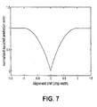
- FIG 7 illustrates a plot of the squared error as a function of misalignment
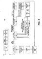
- FIG. 8 illustrates a block diagram of a GPS receiver in accordance with an embodiment of the invention.
- FIG. 9 illustrates a flow diagram in accordance with another embodiment.
- Embodiments pertain generally to a method of processing a received DSSS signal. More particularly, embodiments may be configured to recover an elemental waveform from the received DSSS signal and use minimum prediction error techniques on the recovered elemental waveform to determine a temporal alignment factor for the received DSSS signal relative to a local reference code (or local code replica).
- the correlation of the arriving signal with the sampling local reference code of Fig. 3 to produce the recovered elemental waveform can be accomplished in a mathematically equivalent manner as follows.
- An m-number of accumulators may be allocated, where m may have a value in the range from one to N.
- Each accumulator may be associated with a respective interval in the recovered elemental waveform.
- n indicate the sample number within each of these segments, with 1 ⁇ n ⁇ N.
- Each nth sample of a segment is multiplied by a local reference code corresponding to that segment and the resulting product is added to the nth accumulator.
- the first sample of each arriving signal segment is multiplied by the corresponding local reference code and the 1023 resulting products are then accumulated in the first accumulator.
- the second sample of each arriving signal segment is multiplied by the corresponding local reference code and the 1023 resulting products are then accumulated in the second accumulator, and so forth.
- the accumulated products form a central portion of the elemental waveform.
- the local reference code may be advanced by one chip in conjunction with a second set of m accumulators, and the process of sampling and accumulating products is repeated to form an early portion of the recovered waveform.
- the local reference code may be delayed by one chip in conjunction with a third set of m accumulators and the process of sampling and accumulating products is repeated to form a late portion of the recovered elemental waveform.
- the early, central, and late portions of the recovered elemental waveform may be concatenated to form the recovered elemental waveform.
- the resulting waveform contains a sequence of 3N values within which there is a rectangular function that is one-chip wide with a temporal location that depends on the time of the arrival of the signal.
- the resulting rectangular function may be used to generate a prediction error that involves all the data from the recovered elemental waveform.
- the generated prediction errors may be configured to be input to a discriminator function.
- the values of the discriminator function feed a code loop filter which then determines the temporal alignment of the local reference code and the received DSSS signal.
- Embodiments of the invention resolve the alignment factor in a DSSS signal based on a signal power representation of the DSSS signal and minimum error prediction techniques. More particularly, a DSSS signal is modulated by a binary shift code that flips from a value of "1" to a value of "minus 1" following a pattern determined by a particular pseudorandom noise code known as the Gold code.
- the Gold codes used for example in a GPS system, consist of 1023 values. The code sequences through all 1023 values in one millisecond, and then the cycle begins again.
- FIG 1 illustrates a partial example of a Gold code. As shown in FIG. 1, a seven-chip segment of a 1023 chip Gold code modulation function is depicted. As described previously, the code lakes on values of one or minus one. Each chip has a time width of w. The local reference code is produced in the same way with identical results.
- a property of these Gold codes is that when one such codes is correlated with a time-shifted replica of itself, the correlation value is very large when there is no time shift and very much smaller when the codes are shifted out of alignment.
- a DSSS signal e.g., a GPS signal
- a large value results when the codes are in alignment as illustrated in FIG. 2.
- FIG. 2 may depict the cross correlation of the 1023-Gold chip modulation function with the local replica code.
- the value is 1023 times as large as the value when things are misaligned by more than one chip.
- the correlation decreases linearly as the amount of misalignment increases, resulting in the triangular response near the point of alignment. This triangular behavior is a direct result of the finite rectangular width of each chip.
- N there is an implicit assumption that the DSSS signal e.g., a GPS signal, is being processed with sufficient bandwidth that the appropriate Nyquist sampling rate provides N samples across a code chip.
- N needs to be greater than just one or two for adequate resolution of the code chip, but it need not be really large, as the satellite transmitter that produced the signal has only so much bandwidth.
- Reasonable values of N might fall in the range 10 to 100.
- the local reference codes may be altered, as depicted in FIG. 3. As shown in FIG. 3, a seven-chip portion of the 1023 chips of the local replica code is depicted.
- the local replica code has the the same chipping rate as the C/A code but each chip has a duty cycle such that it has a non-zero value for only a fraction of the chip interval.
- this local replica code is correlated with the DSSS signal, the correlation result is shown in FIG. 4.
- the resulting waveform has a 1023 boost in the signal level value and a rectangular response near the vicinity of perfect alignment instead of a triangular response.
- the correlation property of the Gold codes is being used to collapse the DSSS signal back into a despread signal.
- the prompt response will now have N/2 samples that are the same as before and N/2 samples that are 1023 times smaller. Depending on the direction of the shift, one of the other responses (left or right) will now have N/2 large values and N/2 small values while the remaining responses (right or left) will have all small values. If the responses are placed next to each other as in FIG. 5 the original rectangle located in the aligned prompt response simply moves left or right depending on the amount of misalignment.
- the segment marked L contains the N recovered waveform sample values when the local code is one chip advanced compared to the local code used in segment C.
- the segment marked R contains the N recovered waveform sample values when the local code is one chip delayed compared to the local code used in segment C.
- the arriving modulation code is properly aligned with the local code used to produce segment C.
- the arriving modulation code is delayed one-half chip relative to the local code used to produce segment C.
- a predicted signal can be defined as follows: sum the contents of the central N prompt response and divide by N to get the predicted value for the central, N values. Moreover, assume that the predicted value for the N outputs on the left response and on the right response is simply zero. The subtraction of the predicted signal from the actual signal over the entire 3N responses produces a collection of errors and the sum of the squares of these errors produces a total squared prediction error.
- two additional square prediction errors may be determined by using either the left or the right N values to get a predicted signal level.
- the prediction will be zero and the prediction error will be a maximum.
- the alignment will produce an intermediate nonzero error that increases as the amount of misalignment increases.
- the graph has a minimum when there is no misalignment, and as the misalignment increases, the squared error increases. It can be shown that this error behaves in a quadratic manner, but note the orientation of the quadratic. It is not quadratic with respect to the misalignment, which may be designated as d; instead it is a quadratic of the form A - B ( d -1) 2 for 1 > d > 0 and A - B ( d- 1) 2 for (-1 ⁇ d ⁇ 0), where d has been normalized to the chip width and A and B are appropriate scaling factors (which factor out, as described in greater detail below).
- Three squared error terms may be generated, one when the left analysis window is used to produce a predicted signal, one when the center analysis window is used, and one when the right analysis window is used. In all cases, the error is computed across all samples contained in the region obtained by forming the union of the three analysis windows.
- the three resulting squared prediction errors may be referred to as left error, center error and right error, or ⁇ L 2 , ⁇ C 2 and ⁇ R 2 for short.
- the discriminator function may be derived from multiplying the expression for d (Eq. 4) by 2. This will cause the discriminator to swing from a value of -1 to +1 as the misalignment changes from -1/2 to +1/2, as is the typical case with other discriminator functions used in GPS code lock loops.
- GPS receivers will sometimes make use of what are called quadrature signal components.
- the GPS signal is multiplied by a cosine function with the appropriate frequency, while the quadrature phase component is obtained by using the related sine function.
- quadrature signal components one must compute the squared prediction errors as described above for each of the two components separately and then add the two errors to get the total error terms that should be used in the discriminator function.
- complex-valued signals may be used, complex-valued errors computed and the modulus squared of the complex-valued errors may be used in lieu of handling the I and Q channels separately. Accordingly, ⁇ i 2 may be replaced with
- 2 , i ⁇ L, R, C ⁇ in the above equations to allow for complex-valued signals. In the event that only the I or Q signal is to be processed, the expressions may be straightforwardly reduced to the appropriate real-valued expressions.
- the incoming GPS data may be manipulated to obtain three prediction-error-related terms, namely
- 2 three prediction-error-related terms
- s i represent a sample value from a GPS signal.
- s i is complex valued, with real part equal to the in-phase (1) component and imaginary part equal to the quadrature-phase (Q) component.
- Q quadrature-phase
- S C 1 ⁇ i ⁇ C ⁇ 1 s i
- S C ⁇ 2 ⁇ i ⁇ C ⁇ 2 s i
- S C ⁇ 3 ⁇ i ⁇ C ⁇ 3 s i
- S R ⁇ 1 ⁇ i ⁇ R ⁇ 1 s i .
- Equation 19 may be used: ⁇ ⁇ 2 - ⁇ ⁇ Re ⁇ S C ⁇ 3 * + S R ⁇ 1 * ⁇ 2 ⁇ S C ⁇ 2 + S C ⁇ 3 + S R ⁇ 1 - S L ⁇ 3 * + S C ⁇ 1 * ⁇ S L ⁇ 3 + S C ⁇ 1 + S C ⁇ 2 ⁇ Re ⁇ S C ⁇ 3 * ⁇ 2 ⁇ S C ⁇ 1 + S C ⁇ 2 + S C ⁇ 3 - S L ⁇ 3 * ⁇ S L ⁇ 3 + 2 ⁇ S C ⁇ 1 + S C ⁇ 2 + 2 - ⁇ ⁇ Re ⁇ S R ⁇ 1 * ⁇ 2 ⁇ S C ⁇ 2 + S C ⁇ 3 + S R ⁇ 1 - S C ⁇ 1 * ⁇ S C ⁇ 1 + 2 ⁇ S C ⁇ 2 + S C ⁇ 3 and when Re ⁇ S C ⁇ 3 * + S R ⁇ 1 * ⁇ 2 ⁇ S C ⁇ 2 + S C
- This latter pair of expressions contains a number of common groupings of terms that need only be computed once, so it's not quite as complicated as it first appears. In fact, this latter term can be computed with 12 additions/subtractions and 10 multiply/divides, as compared to 10 additions/subtractions and 7 multiply/divides for the former expression.
- non-uniform antenna response functions can cause variable amplitudes in the received signals.
- lower signal amplitudes may produce proportionally smaller discriminator values and the reverse for higher amplitude signals.
- discriminator values drive the code lock loop and the non-normalized behavior of the discriminator affects the performance of the code lock loop.
- the discriminator function defined by equations 19 and 20 is normalized in such a way that a change in the signal amplitude has no effect on the discriminator value, More particularly, the numerator and denominator change by the same factor when the signal amplitude changes, leaving the discriminator unaffected by the signal amplitude. Moreover, in the ideal deterministic case where each chip is a proper rectangle function, this discriminator function is perfectly linear in its response as the misalignment varies over the distance separating the left and right analysis windows.
- FIG. 8 illustrates a block diagram of a GPS receiver 800 in accordance with an embodiment of the invention. It should be readily apparent to those of ordinary skill in the art that the block diagram depicted in FIG. 8 represents a generalized schematic illustration and that other components may be added or existing components may be removed or modified. Moreover, the GPS receiver 800 may be implemented using software components, hardware components, or a combination thereof.
- the GPS receiver 800 may include an antenna 805, pre-amp module 810, a down conversion 815, an analog/digital (“A/D") converter 820 and a carrier demodulator 830.
- a GPS signal may be received at the antenna 805 and the received GPS signal strength increased by the pre-amp module 810.
- the GPS signal is down converted by the down converter module 815 and inputted to the A/D converter 820.
- the output signal of the A/D converter is a digital representation of the received GPS signal from its analog form.
- the digital GPS signal may then have the carrier wave removed by the carrier demodulator 830.
- the carrier demodulator 830 may also be configured to sample the I and Q components of the GPS signal.
- the I and Q digital samples may then be inputted into the multi-chip signal recovery module 835.
- the bandwidth of the GPS signal is sufficient to resolve more than one sample per code chip.
- the multi-chip signal recovery module 835 may be configured to be part of a first stage processing of the GPS signal.
- the C/A code in the GPS signal is an example of a DSSS signal.
- the received GPS signal must be de-spread via the previously described method for recovering the elemental chip waveform in order for the signal to be detected in the presence of noise. Due to the practicality of the temporal misalignment, the correlation between the arriving signal and the sampling local reference code of the type shown in Fig. 3 must be performed over a range of relative alignments that cover more than a single chip interval in order to obtain the required despread or recovered element waveform data.
- three chip intervals of recovered signal may be used to determine the temporal alignment between a received DSSS signal and the local replica code. In other embodiments, two chip intervals of recovered signal may be used.
- a central set of m accumulators may be used with the received DSSS signal and the prompt local replica code to produce the central portion of the recovered elemental waveform; an early (or left) set of m accumulators may use the received DSSS signal and the early replica code, that is, the prompt local replica code advanced by one chip, to produce the early (or left) portion of the recovered elemental waveform; and a late (or right) set of m accumulators may use the received DSSS signal and the late replica code, that is, the prompt local replica code delayed by one chip, to produce the late (or right) portion of the recovered elemental waveform.
- the multi-chip signal recovery module 835 may use three sets of m accumulators to generate a de-spread GPS signal for an interval three code chips in duration, i.e. a recovered elemental waveform.
- the de-spread data as the recovered elemental waveform may represent a signal amplitude representation of the code chip embedded in the received GPS signal.
- each accumulator in each set of m-accumulators may be associated with a position in the recovered elemental waveform.
- the first accumulator in the center recovery process may be associated with the first sample position of the center portion of the recovered elemental waveform.
- the second accumulator of the late recovery process may be associated with the second sample position of the late portion of the recovered elemental waveform, and so on.
- the first signal sample that arrives immediately after the start of a new chip in the local reference code will be multiplied by the current value of the local reference code and the product accumulated in the first of the m accumulators associated with the center portion of the recovered waveform.
- the second signal sample that arrives after the start of a new chip in the local reference code will be multiplied by the current value of the local reference code and the product accumulated in the second of the m accumulators associated with the center portion of the recovered waveform.
- the nth sample after the start of a new chip in the local reference code will be multiplied by the current value of the local reference code and the product accumulated in the nth of the m accumulators, where n may vary between 1 ⁇ n ⁇ m.
- a similar process to the central portion of the recovered waveform may be performed except that the local replica code has been advanced by one chip. Accordingly, the nth sample after the start of a new chip in the local reference code is multiplied by the current value of the one-chip-advanced local reference code and the product accumulated in the nth-accumulator in the accumulator set associated with the early portion of the recovered waveform, where n may vary between 1 ⁇ n ⁇ m. For the late portion of the recovered waveform, the local replica code has been delayed by one chip.
- nth sample after the start of a new chip in the local reference code is multiplied by the current value of the one-chip-delayed local reference code and the produces accumulated in the nth accumulator in the accumulator set associated with the late portion of the recovered waveform, where n may vary between 1 ⁇ n ⁇ m.
- the multi-chip signal recovery module 835 may also be configured to form the recovered elemental waveform from the accumulated results contained in the early, center and late portions of the recovered waveform. More particularly, the multi-chip signal recovery module 835 may concatenate the early, center and late portions of the recovered waveform in that particular sequence. These concatenated portions of the recovered elemental waveform may be forwarded to the analysis window processing module 845.
- the output of just one one-chip portion of the recovered waveform may be insufficient to predict the alignment of the de-spread C/A code chip. If the C/A code chip is properly aligned, the central one-chip portion would be sufficient. However, in practicality, the C/A code chip signal is typically shifted left or right by some offset. As a result, the neighboring data may provide a determination of whether the C/A code chip has shifted or is properly aligned.
- the determination of alignment may be accomplished using just two one-chip portions of the recovered waveform, where the local reference code is a half-chip early in the first recovery process and the local reference code is a half-chip delayed in the second recovery process.
- the properly aligned de-spread C/A code chip may fall directly in the middle of the 2N-long data set provided by the two-chip recovery processes. Once initial signal acquisition has occurred and the C/A signal is being tracked, the misalignment errors are typically less than half-a-chip and the two-chip recovery process can provide enough data for processing.
- each one-chip recovery process may be allocated m accumulators, where each accumulator is associated with a position in the recovered elemental waveform.
- the local replica code is advanced by a half-chip. The nth sample after the start of a prompt local reference code chip is multiplied by the current value of the one-half-chip early local reference code and the product accumulated in the nth of the m accumulators associated with the first of the two sets of m accumulators, where n may vary between 1 ⁇ n ⁇ m.
- the local replica code is delayed by a half-chip.
- the nth sample after the start of a prompt local reference code chip is multiplied by the current value of the one-half-chip late local reference code and the product accumulated in the nth of the m accumulators associated with the second of the two sets of m accumulators, where n may vary between 1 ⁇ n ⁇ m.
- the early and late portions of the recovered waveform may then be concatenated to form a 2N-long data set and forwarded to the analysis window processing module 845.
- the multi-chip recovery module 835 may further receive signals from the code NCO module 850. These signals may comprise of a new chip flag, an initial sample offsets for early, prompt and late chips. These signals may also be input to the code generator 840.
- the analysis window processing module 840 may be configured to generate the prompt I & Q correlation values to be inputted to the carrier loop discriminator 855 and a reduced array of I & Q values to a power-based code alignment discriminator 860. More particularly, the analysis window processing module 840 may be configured to receive the recovered elemental waveform from the three-chip (or two-chip) recovery processes that represent the signal amplitude representations of the recovered I and Q samples.
- the analysis window processing module 840 may be further configured to use analysis windows in the processing of the combined data array. More particularly, an analysis window of N samples wide may be formed by the analysis window processing module 840. The analysis window processing module 840 may then overlay three analysis windows over the recovered elemental waveform as previously depicted in FIG. 6. For convenience sake, the three analysis windows may be referred to as AW L 605, AW C 610, and AW R 615. In some embodiments, the three analysis windows overlap with a separation of ⁇ . In other embodiments, the ⁇ between AW L and AW C may not be equivalent to the ⁇ between AW C and AW L .
- the AW L 605 comprises of subsegments L3, C1, and C2.
- AW C 610 comprises of C1, C2, and C3
- AW R 615 comprises of C2, C3, and R1.
- the carrier loop discriminator 855 may be configured to determine the phase of the carrier signal that carried the GPS signal. The phase may then be forwarded to the carrier loop filter 865, where the output is fed into the carrier numerical controlled oscillator (“NCO") 870. The carrier NCO 865 may become the timing signal for the carrier sample generator 875.
- NCO carrier numerical controlled oscillator
- the analysis window processing module 845 may yet be further configured to sum the values of subsegments, L3, C1, C2, C3, and R1. More particularly, using L3 as an illustrative example, the analysis window processing module 845 may sum the data contained in the L3 subsegment and refer to this sum as S L3 . Similarly, the data contained in the respective subsegments of C1-C3 and R1 are summed as S C1 , S C2 , S C3 , and S R1 , respectively. The five sums may be referred to as a reduced array of I & Q values, which is then forwarded to the power-based code alignment discriminator 860.
- the power-based code alignment discriminator 860 may be configured to generate an alignment factor that is forwarded to the code loop filter 880.
- the alignment factor may then be used by the code loop filter 880, the code NCO 850 and code generator 840 to align the GPS signal.
- the power-based code alignment discriminator 860 may generate the alignment factor based on a discriminator function that was previously expressed in equations 19 and 20. The mathematical basis for this discriminator function has been described previously in greater detail.
- FIG. 9 illustrates an exemplary flow diagram in accordance to another embodiment of the invention. It should be readily apparent to those of ordinary skill in the art that the flow diagram 900 depicted in FIG. 9 represents a generalized schematic illustration and that other steps may be added or existing steps may be removed or modified.
- the multi-chip recovery module 835 may be configured to receive the direct sequence spread spectrum signal, in step 905. More particularly, the multi-chip recovery module 835 may receive the I & Q signal samples of the received direct sequence spread spectrum signal (e.g., the C/A code) from the carrier demodulator 835.
- the multi-chip recovery module 835 may receive the I & Q signal samples of the received direct sequence spread spectrum signal (e.g., the C/A code) from the carrier demodulator 835.
- the multi-chip recovery module 835 may perform the three-chip recovery processes on the signal samples. More specifically, a center, left and right portion of the recovered waveform are obtained from the I and Q signal samples. As described earlier, the three one-chip recovery processes form the recovered waveform which is then forwarded to the analysis window processing module 845.
- the analysis window processing module 845 may be configured to apply overlapping analysis windows to the recovered elemental waveform.
- the analysis window processing module 845 may be configured to sum the values of the sub-segments, L3, C1, C2, C3, and R1. More particularly, using L3 as an illustrative example, the analysis window processing module 845 may sum the data contained in the L3 sub-segment and refer to this sum as S L3 . Similarly, the data contained in the respective sub-segments of C1-C3 and R1 are summed as S C1 , S C2 , and S R1 , respectively. The five sums may be referred to as a reduced array of I and Q values, which is then forwarded to the power-based code alignment discriminator 860.
- the power-based discriminator 860 may be configured to determine an alignment factor for the received GPS signal. More specifically, the power-based discriminator 860 may apply the sums of the sub-segments into equation 19 or 20 as previously described. The power-based discriminator 860 may then forward the alignment factor to the code loop filter for further processing.
- the computer program may exist in a variety of forms both active and inactive.
- the computer program can exist as software program(s) comprised of program instructions in source code, object code, executable code or other formats; firmware program(s); or hardware description language (HDL) files.
- Any of the above can be embodied on a computer readable medium, which include storage devices and signals, in compressed or uncompressed form.
- Exemplary computer readable storage devices include conventional computer system RAM (random access memory), ROM (read-only memory), EPROM (erasable, programmable ROM), EEPROM (electrically erasable, programmable ROM), and magnetic or optical disks or tapes.
- Exemplary computer readable signals are signals that a computer system hosting or running the present invention can be configured to access, including signals downloaded through the Internet or other networks.
- Concrete examples of the foregoing include distribution of executable software program(s) of the computer program on a CD-ROM or via Internet download. ln a sense, the Internet itself, as an abstract entity, is a computer readable medium. The same is true of computer networks in general.
Landscapes
- Engineering & Computer Science (AREA)
- Computer Networks & Wireless Communication (AREA)
- Signal Processing (AREA)
- Radar, Positioning & Navigation (AREA)
- Remote Sensing (AREA)
- Physics & Mathematics (AREA)
- General Physics & Mathematics (AREA)
- Position Fixing By Use Of Radio Waves (AREA)
Applications Claiming Priority (1)
| Application Number | Priority Date | Filing Date | Title |
|---|---|---|---|
| US11/330,122 US20070160120A1 (en) | 2006-01-12 | 2006-01-12 | Method for code-alignment for DSSS signal processing |
Publications (1)
| Publication Number | Publication Date |
|---|---|
| EP1808967A1 true EP1808967A1 (fr) | 2007-07-18 |
Family
ID=37907276
Family Applications (1)
| Application Number | Title | Priority Date | Filing Date |
|---|---|---|---|
| EP07100502A Withdrawn EP1808967A1 (fr) | 2006-01-12 | 2007-01-12 | Méthode pour l'alignement de codes pour le traitement de signaux DSSS |
Country Status (3)
| Country | Link |
|---|---|
| US (1) | US20070160120A1 (fr) |
| EP (1) | EP1808967A1 (fr) |
| CA (1) | CA2573666A1 (fr) |
Cited By (2)
| Publication number | Priority date | Publication date | Assignee | Title |
|---|---|---|---|---|
| CN103412316A (zh) * | 2013-07-05 | 2013-11-27 | 北京航空航天大学 | 实时定位系统直接序列扩频信号自适应跟踪方法 |
| US10018731B2 (en) | 2014-01-16 | 2018-07-10 | Qinetiq Limited | Processor for a radio receiver |
Families Citing this family (3)
| Publication number | Priority date | Publication date | Assignee | Title |
|---|---|---|---|---|
| WO2014121151A1 (fr) * | 2013-02-01 | 2014-08-07 | Freshstart Systems Inc. | Système de gestion de l'efficacité commerciale réparti |
| US20170261617A1 (en) * | 2015-09-23 | 2017-09-14 | Topcon Positioning Systems, Inc. | Method of reducing inter-channel biases in glonass gnss receivers |
| US12386079B2 (en) * | 2022-03-01 | 2025-08-12 | Sri International | Multi-level aiding signal to support rapid communication |
Citations (1)
| Publication number | Priority date | Publication date | Assignee | Title |
|---|---|---|---|---|
| WO1995014937A1 (fr) * | 1993-11-29 | 1995-06-01 | Novatel Communications Ltd. | Recepteur de bruit pseudo-aleatoire utilise en telemetrie et compensant la distorsion par trajets multiples a l'aide des intervalles de temps de propagation des correlateurs multiples |
Family Cites Families (11)
| Publication number | Priority date | Publication date | Assignee | Title |
|---|---|---|---|---|
| JP2616182B2 (ja) * | 1990-08-29 | 1997-06-04 | 三菱電機株式会社 | データ処理装置 |
| US5511090A (en) * | 1994-03-17 | 1996-04-23 | Tatung Telecom Corporation | Wireless frequency-division-multiple-access direct sequence spread spectrum telephone system |
| US6160841A (en) * | 1996-05-24 | 2000-12-12 | Leica Geosystems Inc. | Mitigation of multipath effects in global positioning system receivers |
| US6151353A (en) * | 1996-07-12 | 2000-11-21 | General Electric Company | Pre-acquisition frequency offset removal in a GPS receiver |
| US6614834B1 (en) * | 1998-09-08 | 2003-09-02 | The Board Of Trustees Of The Leland Stanford Junior University | Communication arrangement and method with fast tracking receiver for spread spectrum signals |
| US6201828B1 (en) * | 1998-11-12 | 2001-03-13 | Nortel Networks Limited | Fine estimation of multipath delays in spread-spectrum signals |
| US6658048B1 (en) * | 2000-04-07 | 2003-12-02 | Nokia Mobile Phones, Ltd. | Global positioning system code phase detector with multipath compensation and method for reducing multipath components associated with a received signal |
| FR2843638B1 (fr) * | 2002-08-13 | 2004-10-22 | Thales Sa | Recepteur de positionnement par satellite avec correction d'erreurs d'inter-correlation |
| US7738536B2 (en) * | 2003-04-15 | 2010-06-15 | Novatel Inc. | Apparatus for and method of making pulse-shape measurements |
| EP1681773A1 (fr) * | 2005-01-13 | 2006-07-19 | Centre National D'etudes Spatiales | Signal à spectre étalé |
| US7738537B2 (en) * | 2005-09-14 | 2010-06-15 | Novatel Inc. | Apparatus for and method of determining quadrature code timing from pulse-shape measurements made using an in-phase code |
-
2006
- 2006-01-12 US US11/330,122 patent/US20070160120A1/en not_active Abandoned
-
2007
- 2007-01-11 CA CA002573666A patent/CA2573666A1/fr not_active Abandoned
- 2007-01-12 EP EP07100502A patent/EP1808967A1/fr not_active Withdrawn
Patent Citations (1)
| Publication number | Priority date | Publication date | Assignee | Title |
|---|---|---|---|---|
| WO1995014937A1 (fr) * | 1993-11-29 | 1995-06-01 | Novatel Communications Ltd. | Recepteur de bruit pseudo-aleatoire utilise en telemetrie et compensant la distorsion par trajets multiples a l'aide des intervalles de temps de propagation des correlateurs multiples |
Cited By (2)
| Publication number | Priority date | Publication date | Assignee | Title |
|---|---|---|---|---|
| CN103412316A (zh) * | 2013-07-05 | 2013-11-27 | 北京航空航天大学 | 实时定位系统直接序列扩频信号自适应跟踪方法 |
| US10018731B2 (en) | 2014-01-16 | 2018-07-10 | Qinetiq Limited | Processor for a radio receiver |
Also Published As
| Publication number | Publication date |
|---|---|
| US20070160120A1 (en) | 2007-07-12 |
| CA2573666A1 (fr) | 2007-07-12 |
Similar Documents
| Publication | Publication Date | Title |
|---|---|---|
| EP1793236B1 (fr) | Fonction de discriminateur améliorée pour alignement de code GPS | |
| US8467433B2 (en) | Apparatus for and method of making pulse-shape measurements | |
| US6658048B1 (en) | Global positioning system code phase detector with multipath compensation and method for reducing multipath components associated with a received signal | |
| US7920093B2 (en) | Methods for improving computational efficiency in a global positioning satellite receiver | |
| US7738606B2 (en) | System and method for making correlation measurements utilizing pulse shape measurements | |
| US6282231B1 (en) | Strong signal cancellation to enhance processing of weak spread spectrum signal | |
| KR100576959B1 (ko) | 고속 포착, 고감도 gps 수신기 | |
| US7738537B2 (en) | Apparatus for and method of determining quadrature code timing from pulse-shape measurements made using an in-phase code | |
| EP1925085B1 (fr) | Appareil et procede de generation de mesures de formes d'impulsions et procede de mise en correlation avec des fronts montants | |
| US6725157B1 (en) | Indoor GPS clock | |
| US20030223477A1 (en) | Signal receiver using coherent integration in interleaved time periods for signal acquisition at low signal strength | |
| US8466836B2 (en) | Fast fourier transform with down sampling based navigational satellite signal tracking | |
| EP1808967A1 (fr) | Méthode pour l'alignement de codes pour le traitement de signaux DSSS | |
| US8665927B2 (en) | Acquisition method with improved multi-frequency correlation | |
| US8391339B2 (en) | Correlator sum method for spread spectrum signal receivers | |
| US7660373B2 (en) | Data demodulation from weak navigational satellite signals | |
| HK1155228B (en) | Method and apparatus for acquisition, tracking, and sub-microsecond time transfer using weak gps/gnss signals |
Legal Events
| Date | Code | Title | Description |
|---|---|---|---|
| PUAI | Public reference made under article 153(3) epc to a published international application that has entered the european phase |
Free format text: ORIGINAL CODE: 0009012 |
|
| AK | Designated contracting states |
Kind code of ref document: A1 Designated state(s): AT BE BG CH CY CZ DE DK EE ES FI FR GB GR HU IE IS IT LI LT LU LV MC NL PL PT RO SE SI SK TR |
|
| AX | Request for extension of the european patent |
Extension state: AL BA HR MK YU |
|
| 17P | Request for examination filed |
Effective date: 20080107 |
|
| AKX | Designation fees paid |
Designated state(s): FR |
|
| 17Q | First examination report despatched |
Effective date: 20080307 |
|
| REG | Reference to a national code |
Ref country code: DE Ref legal event code: 8566 |
|
| GRAP | Despatch of communication of intention to grant a patent |
Free format text: ORIGINAL CODE: EPIDOSNIGR1 |
|
| STAA | Information on the status of an ep patent application or granted ep patent |
Free format text: STATUS: THE APPLICATION IS DEEMED TO BE WITHDRAWN |
|
| 18D | Application deemed to be withdrawn |
Effective date: 20100126 |