EP1809227B1 - In zwei ebenen faltbarer rollstuhl für ältere oder behinderte erwachsene - Google Patents
In zwei ebenen faltbarer rollstuhl für ältere oder behinderte erwachsene Download PDFInfo
- Publication number
- EP1809227B1 EP1809227B1 EP05812956A EP05812956A EP1809227B1 EP 1809227 B1 EP1809227 B1 EP 1809227B1 EP 05812956 A EP05812956 A EP 05812956A EP 05812956 A EP05812956 A EP 05812956A EP 1809227 B1 EP1809227 B1 EP 1809227B1
- Authority
- EP
- European Patent Office
- Prior art keywords
- section
- tubular
- push chair
- sides
- respect
- Prior art date
- Legal status (The legal status is an assumption and is not a legal conclusion. Google has not performed a legal analysis and makes no representation as to the accuracy of the status listed.)
- Expired - Lifetime
Links
Images


Classifications
-
- A—HUMAN NECESSITIES
- A61—MEDICAL OR VETERINARY SCIENCE; HYGIENE
- A61G—TRANSPORT, PERSONAL CONVEYANCES, OR ACCOMMODATION SPECIALLY ADAPTED FOR PATIENTS OR DISABLED PERSONS; OPERATING TABLES OR CHAIRS; CHAIRS FOR DENTISTRY; FUNERAL DEVICES
- A61G5/00—Chairs or personal conveyances specially adapted for patients or disabled persons, e.g. wheelchairs
- A61G5/08—Chairs or personal conveyances specially adapted for patients or disabled persons, e.g. wheelchairs foldable
-
- A—HUMAN NECESSITIES
- A61—MEDICAL OR VETERINARY SCIENCE; HYGIENE
- A61G—TRANSPORT, PERSONAL CONVEYANCES, OR ACCOMMODATION SPECIALLY ADAPTED FOR PATIENTS OR DISABLED PERSONS; OPERATING TABLES OR CHAIRS; CHAIRS FOR DENTISTRY; FUNERAL DEVICES
- A61G5/00—Chairs or personal conveyances specially adapted for patients or disabled persons, e.g. wheelchairs
- A61G5/08—Chairs or personal conveyances specially adapted for patients or disabled persons, e.g. wheelchairs foldable
- A61G5/0808—Chairs or personal conveyances specially adapted for patients or disabled persons, e.g. wheelchairs foldable characterised by a particular folding direction
- A61G5/0816—Chairs or personal conveyances specially adapted for patients or disabled persons, e.g. wheelchairs foldable characterised by a particular folding direction folding side to side, e.g. reducing or expanding the overall width of the wheelchair
- A61G5/0825—Chairs or personal conveyances specially adapted for patients or disabled persons, e.g. wheelchairs foldable characterised by a particular folding direction folding side to side, e.g. reducing or expanding the overall width of the wheelchair comprising a scissor-type frame, e.g. having pivoting cross bars for enabling folding
-
- A—HUMAN NECESSITIES
- A61—MEDICAL OR VETERINARY SCIENCE; HYGIENE
- A61G—TRANSPORT, PERSONAL CONVEYANCES, OR ACCOMMODATION SPECIALLY ADAPTED FOR PATIENTS OR DISABLED PERSONS; OPERATING TABLES OR CHAIRS; CHAIRS FOR DENTISTRY; FUNERAL DEVICES
- A61G5/00—Chairs or personal conveyances specially adapted for patients or disabled persons, e.g. wheelchairs
- A61G5/08—Chairs or personal conveyances specially adapted for patients or disabled persons, e.g. wheelchairs foldable
- A61G5/0808—Chairs or personal conveyances specially adapted for patients or disabled persons, e.g. wheelchairs foldable characterised by a particular folding direction
- A61G5/0833—Chairs or personal conveyances specially adapted for patients or disabled persons, e.g. wheelchairs foldable characterised by a particular folding direction folding front to back, e.g. reducing or expanding the overall depth of the wheelchair
-
- A—HUMAN NECESSITIES
- A61—MEDICAL OR VETERINARY SCIENCE; HYGIENE
- A61G—TRANSPORT, PERSONAL CONVEYANCES, OR ACCOMMODATION SPECIALLY ADAPTED FOR PATIENTS OR DISABLED PERSONS; OPERATING TABLES OR CHAIRS; CHAIRS FOR DENTISTRY; FUNERAL DEVICES
- A61G5/00—Chairs or personal conveyances specially adapted for patients or disabled persons, e.g. wheelchairs
- A61G5/08—Chairs or personal conveyances specially adapted for patients or disabled persons, e.g. wheelchairs foldable
- A61G5/0883—Chairs or personal conveyances specially adapted for patients or disabled persons, e.g. wheelchairs foldable having locking means for maintaining a folded or unfolded condition
Definitions
- the present patent application refers to a push chair for elderly or disabled adults with easily compactable structure.
- the object of the invention falls within the sector of push chairs used to transport elderly or disabled adults, which are mainly composed of a metal tubular structure capable of being compacted in order to reduce volume in non-operating conditions.
- push chairs of this type are made of two identical tubular frames, with basically triangular plan, designed to be mounted one next to the other one to form the sides of the push chair.
- each side is obtained with three different section of metal tube, which are hinged in such a way as to form the three sides of a right-angled triangle.
- the triangular structure includes a longer cathetus in the rear tubular section, with basically vertical direction and designed to support an upper knob to operate the push chair; a shorter cathetus in the lower tubular section, with basically horizontal direction, pivoted on the back on the lower end of the vertical section; and finally the hypotenuse in a tubular section, with inclined direction, basically designed to connect the upper end of the rear/vertical section and the front end of the lower/horizontal section.
- the lower end of the rear vertical section of each side is designed to support a lower wheel, while a second wheel is mounted on the same side under the front end of the lower tubular section, with basically horizontal direction.
- the seat and backrest both with collapsible structure, are fixed between two tubular sides of this type.
- pantograph-shaped crosspieces of which one cross-piece is positioned on the back of the push chair (basically at the height of the back wheels) and the other crosspiece is positioned on the front of the push-chair (in slightly more internal position with respect to front wheels).
- the crosspieces maintain the push chair in operating conditions, preventing the two sides from getting closer accidentally. However, once they are unblocked, they permit to bring the two sides close, until they touch each other, in order to compact the push chair for transportation, storage, and similar purposes.
- Closing of the two sides in terms of depth is made possible by the fact that, in each side, the two tubular sections/catheti fold and translate in such a way that they basically get in contact with the third tubular section/hypotenuse so that the front and the back wheel of each side are in very closed position and the push chair can slide on the four wheels, regardless of being compacted.
- a push chair with the features of the preamble of claim 1 is disclosed in US-A- 3968991 .
- the big volume in terms of depth is due to the perfect alignment, although at close distance, of the two front wheels with the back wheels; and the big volume in terms of height is due to the fact that the tubular section of each side around which the other two tubular sections are compacted (which determines the total height of the push chair in compacted position) is the tubular section/hypotenuse with considerable length.
- the lower ends of the two pairs of tubular sections forming the pantograph-shaped crosspieces are associated with cylindrical sleeves that externally slide on the tubular sections of the corresponding sides, during reciprocating actuation of the crosspieces.
- the two footrest platforms can be laterally rotated and placed edgeways next to the sides; this solution is satisfactory only when the push chair is closed completely and stored away.
- the first purpose of the present invention is to reduce the height of the push chair in compacted position; this result has been obtained by compacting each side with respect to the rear tubular vertical section, rather than the front tubular section/hypotenuse, in such a way that the other elements of the push chair that are being compacted against the push chair do not protrude either in lower or upper position.
- each vertical section ends with a traditional upper handle used to operate the push chair and supports one of the back wheels in lower position.
- the compacting modes of the push chair of the invention are such that, once the push chair has been compacted, the front wheels are places above the back wheels, at a considerable distance from the ground, and no longer in parallel position with the back wheels.
- the push chair of the invention is characterised by considerable manoeuvrability, also in view of the fact that - as mentioned earlier, all the other elements, being mutually compacted, are contained in the intermediate space between the handles and the wheels of the two rear vertical sections.
- Another purpose of the present invention is to minimize the efforts required to compact the push chair and reduce risks of immediate wear of the metal frame; this result has been obtained by devising a new pivoting system between the ordinary pantograph-shaped crosspieces and the tubular sections of the two sides.
- Last, but not least, another purpose of the invention is to minimise the volume in width of the push chair of the invention in operating position, including with the user on board.
- the two footrest platforms are traditionally rotated towards the external face of the sides, and are additionally exactly housed in a suitable space located in the structure of the tubular sides, in such a way that they do not protrude with respect to the sides.
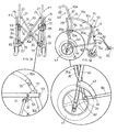
- the push chair of the invention (1) is traditionally formed of two sides with tubular structure (FT) capable of being alternatively brought into a spread operating position (shown in figure 1A ) and in a close resting position (shown in figure 3A ) by means of the interposition of two pantograph-shaped crosspieces (20, 30).
- FT tubular structure
- the first crosspiece (20) is higher than the second crosspiece (30) and is located on the back of the push chair (1), while the second crosspiece (30) is located towards the front of the push chair (1).
- each side with tubular structure (FT) comprises a bearing element formed of a rear tubular section (40) with basically vertical direction.
- a wheel (41) is fixed on the lower end of the vertical tubular section (40), while the upper end (40a) of the vertical tubular section (40), preferably folded backwards, ends with a handle (42); in particular, the backwards folded section (40a) is normally used to fix one of the lateral borders of a backrest (SC) with collapsible structure.
- the wheel shown in the figure belongs to the posterior side (FT) and not to the side (FT) in the foreground.
- an arm (53) facing the front of the push chair (1) is hinged at half height of the vertical tubular section (40) inside a suitable fork (53a) and with respect to a pin with horizontal axis (54), being designed to support the lateral border of a seat (SE) with collapsible structure.
- a pair of identical arched brackets (43), facing the bottom and the front of the push chair (1), with hook-shaped outline, is fixed along the vertical tubular section (40), in intermediate position between the arm (53) and the wheel (41).
- the upper/rear ends of the arched brackets (43) are fixed on opposite sides against the vertical tubular section (40), while the lower/front ends are used to hinge, with respect to a pin with horizontal axis (44), a tubular crossbar (60) with slightly ascending direction towards the front of the push chair (1).
- the front end of the crossbar (60) is hinged, with respect to a pin with horizontal axis (61), towards the lower end of an additional vertical tubular section (70), with curved outline and articulated structure, which supports a swivel wheel (71) in lower position.
- the articulated tubular section (70) extends from the swivel wheel (71) to the backwards folded section (40a) of the rear vertical section (40).
- the first section (70a) is pivoted, with respect to a suitable pin with horizontal axis (73), with the second section (70b) of the vertical section (70); it being provided that the section section (70b) is in turn pivoted in upper position, with respect to a pin with horizontal axis (74), with the third section (70c) of the vertical tubular section (70), which is pivoted on the opposite end, with respect to a pin with horizontal axis (75) in external position with the upper section (40a), slightly inclined backwards, of the rear vertical tubular section (40).
- the upper section (70c), being suitably upholstered, of the articulated vertical section (70) also acts as armrest (B).
- intermediate (70b) and upper (70c) parts of the articulated vertical section (70) are pivoted with compass-shaped configuration.
- a sleeve (80a) is mounted on the lower section (70a), above the point where the entire articulated vertical section (70) and the lower crossbar (60) are hinged, with possibility of rotating by 180°, to support a projecting footrest platform (80).
- the two tubular sides (FT) are connected by means of the aforementioned pantograph-shaped crosspieces (20, 30).
- each crosspiece (20, 30) is formed of a traditional pair of mutually hinged rods, with respect to suitable pins (20a, 30a) with basically horizontal axis.
- the upper ends (21) of the rods of the rear crosspiece (20), i.e. the highest one, are pivoted with respect to pins with horizontal axis (22) on corresponding wings (45) protruding edgeways on the back of the upper section (40a) of the vertical tubular section (40), while the lower ends (23) are hinged, with respected with pins with horizontal axis (24), on the rear ends (62) of the lower tubular crossbars (60).
- the pins (22, 24) used to pivot the rods of the crossbar (20) with respect to the two sides (FT) have an orthogonal position to the pin (20a) used to mutually pivot the rods.
- the upper ends (31) of the front crossbar (30) are pivoted, with respect to pins with horizontal axis (32), on cylindrical bushes (55) mounted in lower position on the arms (53) that support the seat (SE), as expressly shown in the enlargement of figure 1A , while the lower ends (33) are pivoted, with respect to pins with horizontal axis (34), on the lower tubular crossbars (60) of the sides (FT), in more internal position with respect to the hinging point between the latter and the front vertical sections (70).
- pivoting pins (32, 34) have an orthogonal position with respect to the pin (30a) used to mutually pivot the rods of the front crosspiece (30).
- the hinging point between the rods of the front crosspiece (30) and the two tubular crossbars (60) is located in a large concave section (63), with inwards direction, located in each crossbar (60).
- the push chair of the invention (1) can be closed by means of the aforementioned levers by bringing the two tubular sides (FT) in very close position and the articulated front vertical section (70) on the back of the front vertical section (40) because of rototranslation from down upwards and from the front backwards.
- the push chair (1) can be closed by preferably using the two arms (53) designed to support the seat (SE), after releasing a safety lock (not shown in the enclosed figures) that rigidly constrains the front vertical sections (70) of the tubular sides (FT).
- the two arms (53) are rotated upwards and backwards by about 90°, by preferably using their front ends.
- the rotation of the arms (53) determines the simultaneous movement of the two sides (FT), which are brought close, and the upwards backwards rotation of the articulated sections (70) of the sides (FT), so that the sections (70) are brought in close position parallel to the corresponding rear sections (40), although staggered upwards.
- the aforementioned figures also show that the two sides (FT) are gradually brought close while the two rods of the two pantograph-shaped crosspieces (20, 30) are progressively closed, with a progressive higher height of the two crosspieces (20, 30).
- each side (FT) is pivoted, with respect to a pin with horizontal axis (44), to the corresponding pair of arched brackets (43) fixed on the rear vertical section (40).
- FIG. 1B , 2B and 3B shows, in particular, the progressive effects of the thrust discharged when closing the rear crosspiece (20) on the rear ends (62) of the lower tubular crossbars (60) of the two tubular sides (FT).
- the simultaneous upward rotation of the two elements (53, 60) also determines an increase of the distance between the pins (34), which are used to pivot the lower ends (33) of the rods of the crosspiece (30) with the tubular crossbars (60), and the pins (32), which are used to pivot the upper ends (31) of the rods with respect to the bushes (55) located in lower position on the arms (53) that support the seat (SE).
- the articulated parts (70a, 70b, 70c) tend to progressively lose their initial alignment, due to the presence of the pins (72, 73, 74).
- the lower section (70a) and the intermediate section (70b) of the articulated front section (70) are perfectly aligned (with a slightly curved direction), with the upper end of the intermediate section (70b) at the same height as the handle (42) of the fixed rear section (40).
- the upper section (70c) of the articulated section (70) Being constrained next to the fixed vertical section (40), the upper section (70c) of the articulated section (70) is brought in vertical position parallel to the two consecutive parts (70a, 70b).
- the front wheels (71) are placed inside the concave parts (63) of the lower tubular crossbars (60) of the corresponding sides (FT).
- figure 3B shows the position that can be given to the footrest platforms (80) in resting position.
- each footrest platform (80) can rotate from its projecting operating position in front of the push chair by approximately 180°, together with the supporting arm (81), and can be brought next to the side (FT).
- the same platform (80) can also be brought in edgeways position in close contact with the tubular side (FT) to minimize lateral projections.
- the concave parts (63) situated along the lower crossbars (60) of the two tubular sides (FT) of the push chair (1) have a very important function when the push chair is in operating position with the user on board.
- the two platforms (80) can be used to house the two platforms (80), after rotating them laterally in edgeways position; due to this special position, the two platforms do not protrude on the sides of the push chair of the invention (1), thus making manoeuvring easier and safer when the push chair is getting close to a car, a water closet, etc.
- the push chair (1) could operate according to the opening/closing modes as described above also in a version without the intermediate (70b) and upper (70c) parts of the front articulated sections (70) of the tubular sides (FT), that is to say in a constructive embodiment without armrests (B).
Landscapes
- Health & Medical Sciences (AREA)
- Life Sciences & Earth Sciences (AREA)
- Animal Behavior & Ethology (AREA)
- General Health & Medical Sciences (AREA)
- Public Health (AREA)
- Veterinary Medicine (AREA)
- Handcart (AREA)
- Carriages For Children, Sleds, And Other Hand-Operated Vehicles (AREA)
- Rehabilitation Tools (AREA)
- Chairs For Special Purposes, Such As Reclining Chairs (AREA)
- Devices For Medical Bathing And Washing (AREA)
- Special Chairs (AREA)
- Accommodation For Nursing Or Treatment Tables (AREA)
Claims (7)
- Sportwagen für alte oder behinderte Erwachsene des Typs, der aus zwei rohrförmigen Seitenteilen (FT) besteht, zwischen denen ein Sitz (SE) und eine umklappbare Rückenlehne (SC) befestigt sind, die mittels zwei zwischen ihnen befindlichen Pantographenkreuzen (20, 30) aufeinander zu oder voneinander weg bewegt werden können; wobei:- jedes der beiden rohrförmigen Seitenteile (FT) aus einem langen, hinteren Ständer (40) besteht, der unterseitig jeweils ein Rad (41) trägt und zur Spitze hin einen leicht nach hinten geneigten, in einem Griff (42) endenden Abschnitt (40a) aufweist, und aus einer kurzen, vorderen Trägerstange (70a), die unterseitig ein um sich selbst drehendes Pirouettenrad (71) trägt;- der hintere (40) und der vordere Ständer (70a) sind gelenkartig mittels eines unteren Querträgers (60) und eines Sitzträgerarms (53) miteinander verbunden, der dank der Tatsache, dass der Sitzträgerarm (53) mittels geeigneter horizontalachsiger Bolzen (51, 72) angelenkt ist, zwischen einem mittleren Punkt des hinteren Trägers (40) und einem Punkt an der Spitze des vorderen Trägers (70a) geschwenkt werden kann;
dadurch gekennzeichnet, dass:der untere Querträger (60) mittels geeigneter horizontalachsiger Bolzen (44, 61) zwischen dem Ende eines Paares von nach innen und zum Boden des hinteren Trägers (40) hin auskragenden Bügeln (43) und einem in der Nähe des unteren Endes befindlichen Punkt des vorderen Trägers (70a) angelenkt ist; wobei vorgesehen ist, dass die beiden Seitenteile (FT) des Sportwagens (1) mittels der beiden Pantographenkreuze (20, 30) verbunden sind, wobei das hintere Pantographenkreuz (20) so angebracht ist, dass die oberen Enden (21) seiner Stangen mittels geeigneter horizontalachsiger Bolzen (22) mittels schnittförmig stehender, auf der Rückseite der geneigten Abschnitte (40a) der hinteren Ständer (40) der Seitenteile (FT) auskragender Rippen (45) befestigt sind, während die unteren Enden (23) seiner Stangen mittels geeigneter horizontalchsiger Bolzen (24) an den hinteren Enden (62) der rohrförmigen Querträger (60) der Seitenteile (FT) vor dem zwischen den beiden Querträgern (60) und ihren jeweiligen Bügelpaaren (43) vorgesehenen Drehpunkt angelenkt sind; wobei außerdem vorgesehen ist, dass die oberen Enden der Stangen des zweiten, weiter vorn befindlichen und kürzeren Kreuzes (30) mittels horizontalachsiger Bolzen (72) unterhalb der zu den beiden Seitenteilen (FT) gehörenden Sitzträgerarme (53) angelenkt sind, während die unteren Enden dieser Stangen mittels horizontalachsiger Bolzen (34) an den rohrförmigen Querträgern (60) der Seitenteile (FT) an einer - bezogen auf ihren zuvor genannten Drehpunkt mit den vorderen Ständern (70a) - weiter innen gelegenen Stelle angelenkt sind. - Sportwagen für Erwachsene gemäß Anspruch 1, dadurch gekennzeichnet, dass die Sitzträgerarme (53) der beiden Seitenteile (FT) an den hinteren Ständern (40) mittels Gabeln (53a) angelenkt sind, die ins Innere der Ständer überstehen.
- Sportwagen für Erwachsene gemäß einem der vorstehenden Ansprüche, dadurch gekennzeichnet, dass die oberen Enden (31) des vorderen Kreuzes (30) an den jeweiligen Sitzträgerarmen (53) mittels entsprechender horizontalachsiger Buchsen (55) angelenkt sind, die unterhalb derselben vorgesehen sind.
- Sportwagen für Erwachsene gemäß den vorstehenden Ansprüchen, dadurch gekennzeichnet, dass an den beiden vorderen Ständern (70a) seiner Seitenteile (FT) Muffen (80a) angebracht sind, die mittels Auskragung und Zwischenschaltung von längenverstellbaren Armen (81) entsprechende Fußauflagen (80) tragen, die ebenfalls in der Lage sind, eine Drehung um circa 180° nach außen der jeweiligen rohrförmigen Seitenteils (FT) auszuführen, wobei außerdem vorgesehen ist, dass diese Fußauflagen (80) in der Lage sind, in der Nicht-Arbeitsposition eine schnittförmige Stellung bezüglich der Halterungsarme (81) einzunehmen.
- Sportwagen für Erwachsene gemäß den vorstehenden Ansprüche, dadurch gekennzeichnet, dass die rohrförmigen Querträger (60), die unten an den beiden Seitenteilen (FT) vorgesehen sind, konkave, nach innen gerichtete Abschnitte (63) aufweisen, die sich symmetrisch gegenüberliegen und in einer Position zwischen dem vorderen Ende eines jeden Querträgers und seinem zuvor beschriebenen Anlenkpunkt am jeweiligen Bügelpaar (43) besitzen; wobei insbesondere vorgesehen ist, dass jeder konkave Abschnitt (63) in der Lage ist, wenn der Sportwagen (1) sich in Arbeitsposition befindet, die am jeweiligen vorderen Ständer (70a) angelenkte Fußauflage (80) aufzunehmen, wenn diese Fußauflage (80) seitlich gedreht und schnittförmig angeordnet ist, und außerdem das um sich selbst drehbare Pirouettenrad (71), das an der Basis des vorderen Ständers (70a) gehalten wird, aufzunehmen, wenn der Sportwagen (1) sich in geschlossener Ruheposition befindet..
- Sportwagen für Erwachsene gemäß den vorstehenden Ansprüchen, dadurch gekennzeichnet, dass die seitlichen Enden der umklappbaren Rückenlehne (SC) an den nach hinten geneigten Abschnitten (40a) der hinteren Ständer (40) der beiden rohrförmigen Seitenteile (FT) befestigt sind.
- Sportwagen für Erwachsene gemäß den vorstehenden Ansprüchen, dadurch gekennzeichnet, dass im Bereich eines jeden rohrförmigen Seitenteils (FT) sich ein vorderer, gelenkartiger Ständer (70) befindet, der sich aus dem vorderen Rad (71) heraus, seitlich des geneigten Abschnitts (40a) des hinteren Ständers 840) erstreckt, der zusätzlich zum unteren Abschnitt (70a) einen Zwischenabschnitt (70b) und einen oberen Abschnitt (70c) umfasst; wobei vorgesehen ist, dass das untere Ende des Zwischenabschnitts (70b) mittels eines horizontalachsigen Bolzens (73) am oberen Ende des unteren Abschnitts (70a), etwas oberhalb des Anlenkpunktes zwischen dem unteren Abschnitt und dem Sitzträgerarm (53) angelenkt ist; wobei außerdem vorgesehen ist, dass das obere Ende des Zwischenabschnitts (70b) mittels eines horizontalachsigen Bolzens (74) am unteren Ende des oberen Abschnitts (70c) angelenkt ist, der vorzugsweise als Armlehne (B) dient, deren oberes Ende mittels eines horizontalachsigen Bolzens (75) auf der Seite des nach hinten geneigten Abschnitts (40a) des oberen Ständers (40) des jeweiligen rohrförmigen Seitenteils (FT) angelenkt ist; wobei insbesondere vorgesehen ist, dass die beiden Abschnitte (70b, 70c) des gelenkartigen Ständers (70) schenkelartig aneinander angelenkt sind.
Priority Applications (1)
| Application Number | Priority Date | Filing Date | Title |
|---|---|---|---|
| PL05812956T PL1809227T3 (pl) | 2004-11-08 | 2005-11-04 | Pchany wózek dla starszych lub niepełnosprawnych osób dorosłych, składany w dwóch płaszczyznach |
Applications Claiming Priority (2)
| Application Number | Priority Date | Filing Date | Title |
|---|---|---|---|
| IT000133A ITMC20040133A1 (it) | 2004-11-08 | 2004-11-08 | Passeggino per adulti anziani o disabili dotato di una struttura facilmente compattabile |
| PCT/IT2005/000641 WO2006048913A1 (en) | 2004-11-08 | 2005-11-04 | Push chair for elderly or disabled adults foldable in two planes |
Publications (2)
| Publication Number | Publication Date |
|---|---|
| EP1809227A1 EP1809227A1 (de) | 2007-07-25 |
| EP1809227B1 true EP1809227B1 (de) | 2009-04-29 |
Family
ID=35889014
Family Applications (1)
| Application Number | Title | Priority Date | Filing Date |
|---|---|---|---|
| EP05812956A Expired - Lifetime EP1809227B1 (de) | 2004-11-08 | 2005-11-04 | In zwei ebenen faltbarer rollstuhl für ältere oder behinderte erwachsene |
Country Status (10)
| Country | Link |
|---|---|
| US (1) | US7744114B2 (de) |
| EP (1) | EP1809227B1 (de) |
| CN (1) | CN101056600B (de) |
| AT (1) | ATE429889T1 (de) |
| DE (1) | DE602005014260D1 (de) |
| DK (1) | DK1809227T3 (de) |
| ES (1) | ES2328163T3 (de) |
| IT (1) | ITMC20040133A1 (de) |
| PL (1) | PL1809227T3 (de) |
| WO (1) | WO2006048913A1 (de) |
Families Citing this family (5)
| Publication number | Priority date | Publication date | Assignee | Title |
|---|---|---|---|---|
| US7950684B2 (en) * | 2006-10-25 | 2011-05-31 | Jaimie Borisoff | Wheelchair side guards |
| CN103126828A (zh) * | 2013-02-16 | 2013-06-05 | 周兴强 | 便携式折叠轮椅 |
| US11376173B2 (en) | 2016-12-15 | 2022-07-05 | The World's Only Carry-On Wheel Chair, Llc | Wheeled chair |
| US12390377B2 (en) * | 2021-05-28 | 2025-08-19 | Leaderstat, Ltd. | Wheelchair |
| US11364163B1 (en) | 2021-09-28 | 2022-06-21 | Jay Foonberg | Transport chair arranged for storage in passenger aircraft carry-on luggage |
Family Cites Families (19)
| Publication number | Priority date | Publication date | Assignee | Title |
|---|---|---|---|---|
| GB1154362A (en) * | 1965-07-20 | 1969-06-04 | Owen Finlay Maclaren | Improvements relating to Structures for Folding Baby-Carriages, Chairs, and the like |
| GB1446845A (en) * | 1972-11-01 | 1976-08-18 | Gannet Holdings Ltd | Collapsible volume frame structures |
| US4025088A (en) * | 1976-04-13 | 1977-05-24 | Rothschild Barbara G | Folding wheelchair |
| US4062555A (en) * | 1976-11-02 | 1977-12-13 | Peng Luke Shih Cheng | Structure for foldable baby carriage |
| FR2487765A1 (fr) * | 1980-07-31 | 1982-02-05 | Eurolando | Perfectionnements aux poussettes legeres du type repliable |
| US4415202A (en) * | 1981-10-26 | 1983-11-15 | Pew Melvin E | Wheelchair elevating apparatus enabling a user to lift himself from the floor to a wheelchair seat |
| US4572576A (en) * | 1984-08-20 | 1986-02-25 | Quadra Wheelchairs, Inc. | Wheelchair with swingable foot support assemblies |
| US4730842A (en) * | 1986-04-18 | 1988-03-15 | Wheel Ring, Inc. | Adjustable wheelchair |
| GB2200328B (en) * | 1987-01-28 | 1991-05-15 | Spastics Soc | Lightweight foldable wheelchair |
| US4790553A (en) * | 1987-11-16 | 1988-12-13 | Motion Designs, Inc. | Lightweight wheelchair having swing-away footrest assembly |
| US5244223A (en) * | 1992-02-03 | 1993-09-14 | Toshifumi Uchiyama | Wheelchair |
| USD355874S (en) * | 1993-10-12 | 1995-02-28 | Nelson David G | Baby stroller |
| SI9400242A (en) * | 1994-05-30 | 1995-12-31 | Vladimir Markovic | Collapsible wheelchair frame |
| US6113128A (en) * | 1997-07-11 | 2000-09-05 | Convaid Products, Inc. | Mobile seating arrangement |
| USD427550S (en) * | 1999-03-04 | 2000-07-04 | Hsueh-Li Lee | Stroller |
| JP2002225721A (ja) * | 2001-01-31 | 2002-08-14 | Combi Corp | 折畳み式ベビーカー |
| JP3494630B2 (ja) * | 2001-05-18 | 2004-02-09 | 株式会社カトージ | 折り畳み式ベビーカー |
| CN1507847A (zh) * | 2002-12-18 | 2004-06-30 | 高禹丰 | 一种可折叠电动轮椅 |
| CN2696950Y (zh) * | 2004-04-30 | 2005-05-04 | 明门实业股份有限公司 | 可收合式幼儿车架 |
-
2004
- 2004-11-08 IT IT000133A patent/ITMC20040133A1/it unknown
-
2005
- 2005-11-04 PL PL05812956T patent/PL1809227T3/pl unknown
- 2005-11-04 WO PCT/IT2005/000641 patent/WO2006048913A1/en not_active Ceased
- 2005-11-04 ES ES05812956T patent/ES2328163T3/es not_active Expired - Lifetime
- 2005-11-04 DK DK05812956T patent/DK1809227T3/da active
- 2005-11-04 CN CN2005800381341A patent/CN101056600B/zh not_active Expired - Lifetime
- 2005-11-04 EP EP05812956A patent/EP1809227B1/de not_active Expired - Lifetime
- 2005-11-04 DE DE602005014260T patent/DE602005014260D1/de not_active Expired - Lifetime
- 2005-11-04 AT AT05812956T patent/ATE429889T1/de not_active IP Right Cessation
- 2005-11-14 US US11/667,141 patent/US7744114B2/en active Active
Also Published As
| Publication number | Publication date |
|---|---|
| EP1809227A1 (de) | 2007-07-25 |
| ES2328163T3 (es) | 2009-11-10 |
| WO2006048913A1 (en) | 2006-05-11 |
| US20080093821A1 (en) | 2008-04-24 |
| CN101056600B (zh) | 2010-05-26 |
| CN101056600A (zh) | 2007-10-17 |
| DK1809227T3 (da) | 2009-08-17 |
| ATE429889T1 (de) | 2009-05-15 |
| ITMC20040133A1 (it) | 2005-02-08 |
| DE602005014260D1 (de) | 2009-06-10 |
| US7744114B2 (en) | 2010-06-29 |
| PL1809227T3 (pl) | 2009-09-30 |
Similar Documents
| Publication | Publication Date | Title |
|---|---|---|
| KR100333767B1 (ko) | 접철식휠체어 | |
| US4371183A (en) | Folding wheel-chair | |
| US4266807A (en) | Collapsible frame structure for a child's push chair | |
| JPH11155669A (ja) | 改良された移動式座席構成 | |
| FR2761328A3 (fr) | Poussette pliable pour bebe | |
| CN100562302C (zh) | 可进行减速直立操作的直立式轮椅 | |
| CA2825870A1 (fr) | Fauteuil pliant | |
| JPH0223164B2 (de) | ||
| US7744114B2 (en) | Pushchair for elderly or disabled adults foldable in two planes | |
| US2522729A (en) | Collapsible wheel chair | |
| CN114340576A (zh) | 可折叠轮椅 | |
| US7192083B2 (en) | Folding linkage | |
| EP0395719A1 (de) | Senkrecht einstellbar rollender sessel. | |
| CN208119230U (zh) | 一种可折叠儿童推车 | |
| CN209519001U (zh) | 具有可伸缩轮的轮椅及轮椅系统 | |
| FR2627372A1 (fr) | Accoudoirs pour sieges de cabinets d'aisance, abattants et cuvettes comportant de tels accoudoirs | |
| CN221617789U (zh) | 可折叠平台 | |
| CN220513022U (zh) | 折叠式轮椅 | |
| NL1032418C1 (nl) | Rolstoel geschikt voor minder valide personen, voorzien van een verstelbare voetensteun. | |
| CH577312A5 (en) | Hospital bed with centre tilt castor - has frame with lengthwise box sections joined by flat floor and pivoting feet | |
| FR2490086A1 (fr) | Fauteuil transformable en transatlantique avec soutien tournant et appuis-tete separes rabattables | |
| BE1016141A3 (fr) | Armature de fauteuil siege/couchette. | |
| HU218477B (hu) | Összecsukható szánkó | |
| CN117184209A (zh) | 一种联动靠架折叠的婴儿车车架 | |
| FR3013953A1 (fr) | Dispositif de siege articule |
Legal Events
| Date | Code | Title | Description |
|---|---|---|---|
| PUAI | Public reference made under article 153(3) epc to a published international application that has entered the european phase |
Free format text: ORIGINAL CODE: 0009012 |
|
| 17P | Request for examination filed |
Effective date: 20070515 |
|
| AK | Designated contracting states |
Kind code of ref document: A1 Designated state(s): AT BE BG CH CY CZ DE DK EE ES FI FR GB GR HU IE IS IT LI LT LU LV MC NL PL PT RO SE SI SK TR |
|
| 17Q | First examination report despatched |
Effective date: 20071126 |
|
| DAX | Request for extension of the european patent (deleted) | ||
| GRAP | Despatch of communication of intention to grant a patent |
Free format text: ORIGINAL CODE: EPIDOSNIGR1 |
|
| GRAS | Grant fee paid |
Free format text: ORIGINAL CODE: EPIDOSNIGR3 |
|
| GRAA | (expected) grant |
Free format text: ORIGINAL CODE: 0009210 |
|
| AK | Designated contracting states |
Kind code of ref document: B1 Designated state(s): AT BE BG CH CY CZ DE DK EE ES FI FR GB GR HU IE IS IT LI LT LU LV MC NL PL PT RO SE SI SK TR |
|
| REG | Reference to a national code |
Ref country code: GB Ref legal event code: FG4D |
|
| REG | Reference to a national code |
Ref country code: CH Ref legal event code: EP |
|
| REF | Corresponds to: |
Ref document number: 602005014260 Country of ref document: DE Date of ref document: 20090610 Kind code of ref document: P |
|
| REG | Reference to a national code |
Ref country code: IE Ref legal event code: FG4D |
|
| REG | Reference to a national code |
Ref country code: RO Ref legal event code: EPE |
|
| REG | Reference to a national code |
Ref country code: SE Ref legal event code: TRGR |
|
| REG | Reference to a national code |
Ref country code: DK Ref legal event code: T3 |
|
| REG | Reference to a national code |
Ref country code: PL Ref legal event code: T3 |
|
| NLV1 | Nl: lapsed or annulled due to failure to fulfill the requirements of art. 29p and 29m of the patents act | ||
| PG25 | Lapsed in a contracting state [announced via postgrant information from national office to epo] |
Ref country code: FI Free format text: LAPSE BECAUSE OF FAILURE TO SUBMIT A TRANSLATION OF THE DESCRIPTION OR TO PAY THE FEE WITHIN THE PRESCRIBED TIME-LIMIT Effective date: 20090429 Ref country code: AT Free format text: LAPSE BECAUSE OF FAILURE TO SUBMIT A TRANSLATION OF THE DESCRIPTION OR TO PAY THE FEE WITHIN THE PRESCRIBED TIME-LIMIT Effective date: 20090429 Ref country code: LT Free format text: LAPSE BECAUSE OF FAILURE TO SUBMIT A TRANSLATION OF THE DESCRIPTION OR TO PAY THE FEE WITHIN THE PRESCRIBED TIME-LIMIT Effective date: 20090429 |
|
| REG | Reference to a national code |
Ref country code: ES Ref legal event code: FG2A Ref document number: 2328163 Country of ref document: ES Kind code of ref document: T3 |
|
| PG25 | Lapsed in a contracting state [announced via postgrant information from national office to epo] |
Ref country code: SI Free format text: LAPSE BECAUSE OF FAILURE TO SUBMIT A TRANSLATION OF THE DESCRIPTION OR TO PAY THE FEE WITHIN THE PRESCRIBED TIME-LIMIT Effective date: 20090429 Ref country code: LV Free format text: LAPSE BECAUSE OF FAILURE TO SUBMIT A TRANSLATION OF THE DESCRIPTION OR TO PAY THE FEE WITHIN THE PRESCRIBED TIME-LIMIT Effective date: 20090429 Ref country code: IS Free format text: LAPSE BECAUSE OF FAILURE TO SUBMIT A TRANSLATION OF THE DESCRIPTION OR TO PAY THE FEE WITHIN THE PRESCRIBED TIME-LIMIT Effective date: 20090829 Ref country code: NL Free format text: LAPSE BECAUSE OF FAILURE TO SUBMIT A TRANSLATION OF THE DESCRIPTION OR TO PAY THE FEE WITHIN THE PRESCRIBED TIME-LIMIT Effective date: 20090429 |
|
| PG25 | Lapsed in a contracting state [announced via postgrant information from national office to epo] |
Ref country code: EE Free format text: LAPSE BECAUSE OF FAILURE TO SUBMIT A TRANSLATION OF THE DESCRIPTION OR TO PAY THE FEE WITHIN THE PRESCRIBED TIME-LIMIT Effective date: 20090429 |
|
| PG25 | Lapsed in a contracting state [announced via postgrant information from national office to epo] |
Ref country code: BE Free format text: LAPSE BECAUSE OF FAILURE TO SUBMIT A TRANSLATION OF THE DESCRIPTION OR TO PAY THE FEE WITHIN THE PRESCRIBED TIME-LIMIT Effective date: 20090429 Ref country code: SK Free format text: LAPSE BECAUSE OF FAILURE TO SUBMIT A TRANSLATION OF THE DESCRIPTION OR TO PAY THE FEE WITHIN THE PRESCRIBED TIME-LIMIT Effective date: 20090429 |
|
| PLBE | No opposition filed within time limit |
Free format text: ORIGINAL CODE: 0009261 |
|
| STAA | Information on the status of an ep patent application or granted ep patent |
Free format text: STATUS: NO OPPOSITION FILED WITHIN TIME LIMIT |
|
| PG25 | Lapsed in a contracting state [announced via postgrant information from national office to epo] |
Ref country code: BG Free format text: LAPSE BECAUSE OF FAILURE TO SUBMIT A TRANSLATION OF THE DESCRIPTION OR TO PAY THE FEE WITHIN THE PRESCRIBED TIME-LIMIT Effective date: 20090729 |
|
| 26N | No opposition filed |
Effective date: 20100201 |
|
| PG25 | Lapsed in a contracting state [announced via postgrant information from national office to epo] |
Ref country code: MC Free format text: LAPSE BECAUSE OF NON-PAYMENT OF DUE FEES Effective date: 20091130 |
|
| REG | Reference to a national code |
Ref country code: CH Ref legal event code: PL |
|
| REG | Reference to a national code |
Ref country code: IE Ref legal event code: MM4A |
|
| PG25 | Lapsed in a contracting state [announced via postgrant information from national office to epo] |
Ref country code: CZ Free format text: LAPSE BECAUSE OF NON-PAYMENT OF DUE FEES Effective date: 20091104 |
|
| PG25 | Lapsed in a contracting state [announced via postgrant information from national office to epo] |
Ref country code: GR Free format text: LAPSE BECAUSE OF FAILURE TO SUBMIT A TRANSLATION OF THE DESCRIPTION OR TO PAY THE FEE WITHIN THE PRESCRIBED TIME-LIMIT Effective date: 20090730 Ref country code: CH Free format text: LAPSE BECAUSE OF NON-PAYMENT OF DUE FEES Effective date: 20091130 Ref country code: IE Free format text: LAPSE BECAUSE OF NON-PAYMENT OF DUE FEES Effective date: 20091104 Ref country code: LI Free format text: LAPSE BECAUSE OF NON-PAYMENT OF DUE FEES Effective date: 20091130 |
|
| PG25 | Lapsed in a contracting state [announced via postgrant information from national office to epo] |
Ref country code: RO Free format text: LAPSE BECAUSE OF NON-PAYMENT OF DUE FEES Effective date: 20090429 |
|
| PG25 | Lapsed in a contracting state [announced via postgrant information from national office to epo] |
Ref country code: LU Free format text: LAPSE BECAUSE OF NON-PAYMENT OF DUE FEES Effective date: 20091104 |
|
| PG25 | Lapsed in a contracting state [announced via postgrant information from national office to epo] |
Ref country code: HU Free format text: LAPSE BECAUSE OF FAILURE TO SUBMIT A TRANSLATION OF THE DESCRIPTION OR TO PAY THE FEE WITHIN THE PRESCRIBED TIME-LIMIT Effective date: 20091030 |
|
| PG25 | Lapsed in a contracting state [announced via postgrant information from national office to epo] |
Ref country code: CY Free format text: LAPSE BECAUSE OF FAILURE TO SUBMIT A TRANSLATION OF THE DESCRIPTION OR TO PAY THE FEE WITHIN THE PRESCRIBED TIME-LIMIT Effective date: 20090429 |
|
| PG25 | Lapsed in a contracting state [announced via postgrant information from national office to epo] |
Ref country code: PT Free format text: LAPSE BECAUSE OF FAILURE TO SUBMIT A TRANSLATION OF THE DESCRIPTION OR TO PAY THE FEE WITHIN THE PRESCRIBED TIME-LIMIT Effective date: 20090929 |
|
| PG25 | Lapsed in a contracting state [announced via postgrant information from national office to epo] |
Ref country code: TR Free format text: LAPSE BECAUSE OF FAILURE TO SUBMIT A TRANSLATION OF THE DESCRIPTION OR TO PAY THE FEE WITHIN THE PRESCRIBED TIME-LIMIT Effective date: 20090429 |
|
| REG | Reference to a national code |
Ref country code: FR Ref legal event code: PLFP Year of fee payment: 11 |
|
| REG | Reference to a national code |
Ref country code: FR Ref legal event code: PLFP Year of fee payment: 12 |
|
| REG | Reference to a national code |
Ref country code: FR Ref legal event code: PLFP Year of fee payment: 13 |
|
| PGFP | Annual fee paid to national office [announced via postgrant information from national office to epo] |
Ref country code: SE Payment date: 20191128 Year of fee payment: 15 |
|
| PGFP | Annual fee paid to national office [announced via postgrant information from national office to epo] |
Ref country code: DK Payment date: 20191125 Year of fee payment: 15 |
|
| REG | Reference to a national code |
Ref country code: DK Ref legal event code: EBP Effective date: 20201130 |
|
| REG | Reference to a national code |
Ref country code: SE Ref legal event code: EUG |
|
| PG25 | Lapsed in a contracting state [announced via postgrant information from national office to epo] |
Ref country code: SE Free format text: LAPSE BECAUSE OF NON-PAYMENT OF DUE FEES Effective date: 20201105 |
|
| PG25 | Lapsed in a contracting state [announced via postgrant information from national office to epo] |
Ref country code: DK Free format text: LAPSE BECAUSE OF NON-PAYMENT OF DUE FEES Effective date: 20201130 |
|
| PGFP | Annual fee paid to national office [announced via postgrant information from national office to epo] |
Ref country code: IT Payment date: 20221011 Year of fee payment: 18 Ref country code: GB Payment date: 20221122 Year of fee payment: 18 Ref country code: FR Payment date: 20221122 Year of fee payment: 18 Ref country code: ES Payment date: 20221213 Year of fee payment: 18 Ref country code: DE Payment date: 20221128 Year of fee payment: 18 |
|
| REG | Reference to a national code |
Ref country code: DE Ref legal event code: R119 Ref document number: 602005014260 Country of ref document: DE |
|
| GBPC | Gb: european patent ceased through non-payment of renewal fee |
Effective date: 20231104 |
|
| PG25 | Lapsed in a contracting state [announced via postgrant information from national office to epo] |
Ref country code: DE Free format text: LAPSE BECAUSE OF NON-PAYMENT OF DUE FEES Effective date: 20240601 |
|
| PG25 | Lapsed in a contracting state [announced via postgrant information from national office to epo] |
Ref country code: GB Free format text: LAPSE BECAUSE OF NON-PAYMENT OF DUE FEES Effective date: 20231104 |
|
| PG25 | Lapsed in a contracting state [announced via postgrant information from national office to epo] |
Ref country code: FR Free format text: LAPSE BECAUSE OF NON-PAYMENT OF DUE FEES Effective date: 20231130 |
|
| PG25 | Lapsed in a contracting state [announced via postgrant information from national office to epo] |
Ref country code: GB Free format text: LAPSE BECAUSE OF NON-PAYMENT OF DUE FEES Effective date: 20231104 Ref country code: FR Free format text: LAPSE BECAUSE OF NON-PAYMENT OF DUE FEES Effective date: 20231130 Ref country code: DE Free format text: LAPSE BECAUSE OF NON-PAYMENT OF DUE FEES Effective date: 20240601 |
|
| PG25 | Lapsed in a contracting state [announced via postgrant information from national office to epo] |
Ref country code: IT Free format text: LAPSE BECAUSE OF NON-PAYMENT OF DUE FEES Effective date: 20231104 |
|
| PG25 | Lapsed in a contracting state [announced via postgrant information from national office to epo] |
Ref country code: IT Free format text: LAPSE BECAUSE OF NON-PAYMENT OF DUE FEES Effective date: 20231104 |
|
| REG | Reference to a national code |
Ref country code: ES Ref legal event code: FD2A Effective date: 20250102 |
|
| PGFP | Annual fee paid to national office [announced via postgrant information from national office to epo] |
Ref country code: PL Payment date: 20241008 Year of fee payment: 20 |
|
| PG25 | Lapsed in a contracting state [announced via postgrant information from national office to epo] |
Ref country code: ES Free format text: LAPSE BECAUSE OF NON-PAYMENT OF DUE FEES Effective date: 20231105 |
|
| PG25 | Lapsed in a contracting state [announced via postgrant information from national office to epo] |
Ref country code: ES Free format text: LAPSE BECAUSE OF NON-PAYMENT OF DUE FEES Effective date: 20231105 |