EP1809856B1 - Tube transporteur pour une utilisation durant l'installation ou le remplacement d'un outil de forage dans un puits de production et procedures pour son utilisation - Google Patents
Tube transporteur pour une utilisation durant l'installation ou le remplacement d'un outil de forage dans un puits de production et procedures pour son utilisation Download PDFInfo
- Publication number
- EP1809856B1 EP1809856B1 EP05807515A EP05807515A EP1809856B1 EP 1809856 B1 EP1809856 B1 EP 1809856B1 EP 05807515 A EP05807515 A EP 05807515A EP 05807515 A EP05807515 A EP 05807515A EP 1809856 B1 EP1809856 B1 EP 1809856B1
- Authority
- EP
- European Patent Office
- Prior art keywords
- conveyor tube
- well
- tube
- well tool
- receiving unit
- Prior art date
- Legal status (The legal status is an assumption and is not a legal conclusion. Google has not performed a legal analysis and makes no representation as to the accuracy of the status listed.)
- Expired - Lifetime
Links
Images



Classifications
-
- E—FIXED CONSTRUCTIONS
- E21—EARTH OR ROCK DRILLING; MINING
- E21B—EARTH OR ROCK DRILLING; OBTAINING OIL, GAS, WATER, SOLUBLE OR MELTABLE MATERIALS OR A SLURRY OF MINERALS FROM WELLS
- E21B23/00—Apparatus for displacing, setting, locking, releasing or removing tools, packers or the like in boreholes or wells
- E21B23/08—Introducing or running tools by fluid pressure, e.g. through-the-flow-line tool systems
Definitions
- This invention relates to a conveyor tube for use in installing or replacing a well tool in a producing well. More specifically it is a conveyor tube which runs along the outside of the production tube of the producing well, wherein the conveyor tube is designed to be able to move well tools, which may be for example, but are not limited to, sensors for sensing well parameters and/or flow directors for guiding circulation in sections of the production tube, to a predetermined position.
- well tools which may be for example, but are not limited to, sensors for sensing well parameters and/or flow directors for guiding circulation in sections of the production tube, to a predetermined position.
- the invention also relates to procedures for using it.
- Apparatus and methods are also known of introducing tubing into a producing well or the annular space between the casing string and the production tube, such as the examples described in US Patent Number 5,927,405 (in the name Monjure et . al .) and Canadian Patent Application CA 2,339,715 (in the names Cadrin and Hayes ).
- TFL Through Flow Line
- Pump Down Tools Pump Down Tools
- WO2004/066000 discloses an apparatus and method for deployment and replacement of optical fibre through a fitting at the surface, in order to establish the connection to a device permanently located in the well bore.
- WO 2004/066000 is considered the closest prior art and forms the basis for the preamble of claim 1.
- the apparatus is in the form of a fiber optic sensor assembly capable of deployment down an instrumentation tube located in a well bore, including a flexible protective tube having a lumen encasing an optical fiber having a core portion and a cladding portion disposed within the flexible tube.
- the flexible protective tube protects the optical fiber from the oil, water or hydrogen gas within the well bore.
- a optical fiber having a core and a cladding surrounded by the flexible protective tubing is deployed into the lumen of a tube disposed within the well bore by pumping a high pressure fluid into the lumen of the tube, thereby causing the deployment of the optical fiber down the well bore.
- the protective tubing is impermeable of hydrogen and other corrosive materials.
- the object of the invention is to obviate or at least reduce one or more disadvantages of the method of prior art.
- a conveyor tube for use in installing or replacing a well tool in a producing well, wherein the conveyor tube is installed on the outside of a production tube in the well, and wherein the well tool is fed into the conveyor tube, characterised in that the conveyor tube comprises at least one receiving unit in the well, the at least one receiving unit being configured such that a well tool pumped into the conveyor tube can be engaged into the at least one receiving unit and at least a section of the conveyor tube runs between a valve tree and the at least one receiving unit in the well.
- the conveyor tube may consist, for example, but are not limited to, tubes screwed together or coiled tubes, which are preferably installed at the same time as the well completion.
- the well is provided with two or more receiving units, which are installed so that they connect to fluid connection ducts which create a fluid connection between the inside of the conveyor tube and the inside of the production tube.
- the well tool and the receiving unit are designed to engage with each other so that the well tool mentioned is blocked from further movement in the receiving unit.
- at least one receiving unit is provided with a unique locking profile which is designed, to engage with an approaching well tool which is provided with a locking profile which is complementary to the unique locking tool mentioned.
- a well tool may therefore be fed down through the conveyor tube and pass through one or more non-complementary locking profiles before it finally, and preferably, locks into a receiving unit.
- the well tool is arranged to be pumped down through the conveyor tube by a known method using a fluid which is pumped by means of a pump device and packing system installed on the valve tree, for example.
- the well tool is arranged for lowering into the conveyor tube, where the well tool is attached to a wire or control cable which may be, for example, but is not limited to, an electric cable, a fibre optic cable or a combination of these.
- the well tool is released from the lock in the receiving unit and is moved up through the conveyor tube under the influence of fluid pressure or, in cases where wires or a control cable are used, when the wire or control cable is pulled against the surface.
- the conveyor tube is designed to receive one or more sensors designed for sensing one or more well parameters, in one or more receiving units. At least one sensor senses the current well parameter or parameters from the well fluid present at any time in the fluid connection duct between the production tube and conveyor tube.
- the sensor is held in position in the receiving unit by the differential pressure between the conveyor tube and the production tube. In this design there is no need for the sensor to be provided with a locking device that keeps the sensor steady in relation to the receiving unit.
- the sensor is provided with a locking device which engages with a complementary locking device in the receiving unit mentioned, as previously described.
- the conveyor tube is designed to receive one or more flow correctors in the receiving unit to which the conveyor tube is connected.
- the flow corrector is designed to engage with the locking device of a predetermined receiving unit.
- the flow corrector is designed to conduct a fluid flow in the conveyor tube down through the conveyor tube.
- the flow corrector is designed to conduct the fluid flow in the conveyor tube out through the fluid connection duct, which opens to the fluid connection between the conveyor tube and the production tube.
- the flow corrector is designed to conduct the fluid flow in the conveyor tube both down through the conveyor tube and out through the aforementioned fluid connection duct.
- the flow corrector is designed to block all further flow.
- the conveyor tube is designed to receive both one or more sensors and one or more flow correctors.
- a method for installing or replacing a well tool in a producing well wherein the conveyor tube is installed on the outside of a production tube in the well, and wherein the well tool is fed into a conveyor tube, characterised in that the conveyor tube comprises at least one receiving unit in the well, the at least one receiving unit being configured such that a well tool pumped into the conveyor tube can be engaged into the at least one receiving unit and at least a section of conveyor tube runs between a valve tree and the at least one receiving unit in the well.
- valve tree 20 of the vertical type provided with valves of a known type which are known in the specialist field as "hydraulic master valve” 22, a “master valve” 24, a “swab valve” 26 and a side valve 28, through which the production fluids in the well flow on out to a tube arrangement not shown.
- the valve tree 20 is provided in an upper end section with a top cover 30, to which is secured a pressure gauge 31.
- An expert in the field will be aware of the function of valve tree 20, and for this reason it will not be described in more detail.
- the reference number 1 designates a section of a well consisting of a production tube 3 and a feeds tube 5.
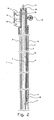
- a conveyor tube 10 which projects from a valve tree 20 down into well 1 via a first receiving unit 12, which is provided with a through hole 16, and down to a second receiving unit 14, in which conveyor tube 10 has its lower end connection point 14'.
- Conveyor tube 10 is connected to the first receiving unit 12 in an upper connection point 12' and a lower connection point 12''.
- the connection between conveyor tube 10 and receiving units 12, 14 can be made, for example, by means of a screw connection or welded joint.
- the second receiving unit is provided with a non-through hole 16', which is in fluid communication with a side hole 16" made in the receiving unit.
- conveyor tube 10 can be connected to any number of receiving units.
- Receiving units 12, 14 are shown in the design examples as integrated with production unit 3. In alternative designs (not shown) the receiving units can be secured to a section of production tube 3.
- conveyor tube 10 When reference is made in the following to conveyor tube 10, this is also interpreted as including receiving units 12, 14, since in the operating situation they constitute a section of conveyor tube 10.
- Production tube 3 is provided with holes which in turn provide fluid connection ducts 3' between production tube 3 and holes 16, 16' in receiving units 12, 14.
- Each receiving element 12, 14 is shown in Figure 1 as being provided with one fluid connection duct 3'.
- production tube 3 may be provided with two or more holes 3', which in turn provide a fluid connection between production tube 3 and each of receiving units 12, 14 of conveyor tube 10.
- Each of receiving units 12, 14 of conveyor tube 10 are provided with a unique locking profile 18, see Fig. 4 , which is designed to receive a well tool 40, see Fig. 2 , which is provided with a locking element 18' complementary to the aforementioned unique locking profile 18, which element can best be seen in Fig. 4 and Fig. 5 .
- Locking element 18' of well tool 40 is arranged, in a preferred design, to be able to pass through a non-complementary locking profile 18 in receiving units 12, and is fed on through the conveyor tube to the next receiving unit 14, as shown in Fig. 2 , where the well tool consists of a sensor 40 which is installed in receiving unit 14 and which communicates with the surface via a sensor cable 42. Fluid connection duct 3' to upper receiving unit 12 is blocked by a well tool comprising a flow corrector 41, which will be described in more detail later.
- Well tool 40 can be lowered down into a well 1 by gravity. In wells with a deviation (not shown) relative to the vertical plane it may be difficult or impossible to feed a well tool 40 along conveyor tube 3 solely on the basis of gravity.
- An intrinsically known method that is difficult to use to convey well tools in tubes involves using a fluid flow which is brought about by a pumping device (not shown).
- Figure 3 shows the upper end section of conveyor tube 10, see Figs. 1 and 2 , connected to a known introducing arrangement 50, where well tool in the form of a sensor 40 is introduced into a sluice chamber 52.
- a sluice chamber In the specialist field such a sluice chamber is often referred to as a "lubricator”.
- Cable 42 of sensor 40 is fed through a sealing arrangement 54 in an upper end section of sluice chamber 52.
- the sealing arrangement consists of a sealing housing 56, which in the specialist field is known as a "stuffing box", and packings and tightening devices of known type, which are shown in the drawings but which will not be described further.
- Fluid for example a liquid
- a valve 58 which fluid will drive sensor 40 into conveyor tube 10 and on down through it by a known method.
- Fig. 3 also shows a valve 60 for isolating conveyor tube 3 and an outlet tube 62, with outlet valve 64 for pressure control and monitoring of conveyor tube 10.
- the device shown in Figure 3 may in principle also be used for pumping in a cable-free flow regulator.
- the sealing housing the so-called “stuffing box”
- a tight end plug of a known type.
- Sensor 40 shown in Fig. 3 , is provided in its free end section with a plurality of circular elastic elements 44 designed to be supported against the inner wall of sluice chamber 52 and conveyor tube 10, so that as much of the fluid as possible which is pumped into sluice chamber 52 and on into conveyor tube 10 drives sensor 40 down into conveyor tube 10 until sensor 40 engages with a predetermined receiving unit 12, 14, see Fig. 1 .
- Fig. 4 shows a section of Fig. 2 on a larger scale, in which sensor 40, shown in outline, has been installed in the second receiving unit 14, and where locking element 18' of sensor 40 engages with the complementary locking profile 18 of receiving unit 14.
- a closing valve 46 of a known type, fitted in receiving unit 14, is rotated by sensor 40 to the open position.
- closing valve 46 is provided with a pre-tensioning device such as an intrinsically known spring device (not shown). The purpose of closing valve 46 is to prevent production fluids from being forced up through conveyor tube 10 when sensor 40 is withdrawn from receiving unit 14, and closing valve 46 of the pre-tensioning device is rotated and blocks fluid flow through hole 16' and on up through conveyor 10, since it will not normally be produced through conveyor tube 10.
- Figure 5 shows a first flow corrector 41 installed in a receiving unit 12, and a second flow corrector 43 installed in a receiving unit 13 at the bottom.
- first flow corrector 41 aforementioned, is provided with an essentially central through hole 41' which, when locking element 18' of flow corrector 41 engages with locking profile 18 of receiving unit 12, conducts fluid flow F past fluid connection duct 3' and on down through conveyor tube 10.
- Second flow corrector 43 is provided with an essentially central blind hole 43', which communicates with a side hole 43''.
- Well tools 40, 41, 43 are disengaged from receiving units 12, 14 by a known method, for example by, but not limited to, carrying out repeated pressure settings and bleeding of the conveyor tube, or by using mechanical devices, e.g. setting/pulling tools (not shown) designed to release locking elements 18' from engagement with locking profiles 18. This is well known to an expert in the field, and will not be described in greater detail.
Landscapes
- Geology (AREA)
- Life Sciences & Earth Sciences (AREA)
- Engineering & Computer Science (AREA)
- Mining & Mineral Resources (AREA)
- Geochemistry & Mineralogy (AREA)
- Fluid Mechanics (AREA)
- Environmental & Geological Engineering (AREA)
- General Life Sciences & Earth Sciences (AREA)
- Physics & Mathematics (AREA)
- Pipeline Systems (AREA)
- Control Of Conveyors (AREA)
- Perforating, Stamping-Out Or Severing By Means Other Than Cutting (AREA)
- Mechanical Pencils And Projecting And Retracting Systems Therefor, And Multi-System Writing Instruments (AREA)
- Hand Tools For Fitting Together And Separating, Or Other Hand Tools (AREA)
- Rotary Presses (AREA)
- Branch Pipes, Bends, And The Like (AREA)
- Structure Of Belt Conveyors (AREA)
Claims (16)
- Tube transporteur (10) destiné à être utilisé pour installer ou remplacer un outil de puits (40) dans un puits de production (1), où le tube transporteur (10) est installé sur l'extérieur d'un tube de production (3) dans le puits (1), et où l'outil de puits (40) est introduit dans le tube transporteur (10), caractérisé en ce que le tube transporteur (10) comprend au moins une unité réceptrice (12, 13, 14) dans le puits (1), cette au moins une unité réceptrice (12, 13, 14) étant configurée de telle sorte qu'un outil de puits (40) pompé dans le tube transporteur (10) puisse être mis en prise dans cette au moins une unité réceptrice (12, 13, 14) et au moins une section du tube transporteur (10) passe entre un arbre de soupape (20) et cette au moins une unité réceptrice (12, 13, 14) dans le puits (1).
- Tube transporteur (10) selon la revendication 1, caractérisé en ce que l'intérieur du tube transporteur (10) est en communication de fluide avec l'intérieur du tube de production (3) au moyen d'au moins un conduit de raccordement de fluide (3') installé de sorte qu'il se raccorde à chaque au moins une unité réceptrice (12, 13, 14).
- Tube transporteur (10) selon la revendication 1 ou la revendication 2, caractérisé en ce que le tube transporteur (10) est conçu pour empêcher l'outil de puits (40) de se déplacer plus avant dans le tube transporteur (10) lorsque l'outil de puits (40) se trouve dans une position prédéterminée.
- Tube transporteur (10) selon la revendication 3, caractérisé en ce que la position prédéterminée mentionnée ci-dessus se trouve dans au moins une des unités réceptrices (12, 13, 14).
- Tube transporteur (10) selon la revendication 3 ou la revendication 4, caractérisé en ce que chaque au moins une unité réceptrice parmi les unités réceptrices (12, 13, 14) est équipée d'un profil de verrouillage unique (18) qui est conçu pour recevoir un outil de puits (40) avec un élément de verrouillage (18') complémentaire au profil de verrouillage unique mentionné ci-dessus (18).
- Tube transporteur (10) selon n'importe laquelle des revendications précédentes, caractérisé en ce que le tube transporteur (10) est conçu pour recevoir un outil de puits comprenant un ou plusieurs capteurs (40) qui sont conçus pour capter un ou plusieurs paramètres de puits.
- Tube transporteur (10) selon la revendication 6, caractérisé en ce qu'au moins un des capteurs (40) est équipé d'un câble (42) conçu pour amener une communication entre au moins un des capteurs (40) et une unité de contrôle en surface.
- Tube transporteur (10) selon n'importe lesquelles des revendications 1 à 4, caractérisé en ce que le tube transporteur (10) est conçu pour transporter et verrouiller un outil de puits comprenant un ou plusieurs correcteurs d'écoulement (41, 43).
- Tube transporteur (10) selon la revendication 8, caractérisé en ce que le correcteur d'écoulement (41) consiste en un élément essentiellement cylindrique pourvu d'un trou débouchant central (41').
- Tube transporteur (10) selon la revendication 8 lorsqu'elle dépend de la revendication 2 ou n'importe quelle revendication de celle-ci, caractérisé en ce que le correcteur d'écoulement (43) consiste en un élément essentiellement cylindrique qui est pourvu d'un trou borgne central (43') qui est en communication de fluide avec un trou latéral (43"), où le trou latéral (43") correspond au conduit de raccordement de fluide (3') lorsqu'un élément de verrouillage (18') du correcteur d'écoulement (43) se met en prise avec un profil de verrouillage (18) de l'unité réceptrice (13), et où les trous (43', 43", 3') sont conçus pour maintenir une communication de fluide entre une section du tube transporteur (10) et le tube de production (3).
- Méthode destinée à installer ou remplacer un outil de puits (40) dans un puits de production (1), où un tube transporteur (10) est installé sur l'extérieur d'un tube de production (3) dans le puits (1), et où l'outil de puits (40) est introduit dans le tube transporteur, caractérisé en ce que le tube transporteur (10) comprend au moins une unité réceptrice (12, 13, 14) dans le puits (1), cette au moins une unité réceptrice (12, 13, 14) étant configurée de telle sorte qu'un outil de puits (40) pompé dans le tube transporteur (10) puisse être mis en prise dans cette au moins une unité réceptrice (12, 13, 14) et au moins une section de tube transporteur passe entre un arbre de soupape (20) et cette au moins une unité réceptrice (12, 13, 14) dans le puits (1).
- Méthode selon la revendication 11, caractérisée en ce que l'outil de puits (40) est descendu par pompage à travers le tube transporteur (10).
- Méthode selon la revendication 11, caractérisée en ce que l'outil de puits (40) est transporté hors du tube transporteur (10) sous l'influence de la pression de fluide.
- Méthode selon la revendication 11, caractérisée en ce que l'outil de puits (40) est abaissé à travers le tube transporteur (10) après un élément de tirage qui a été installé entre l'outil de puits (40) et une extrémité d'entrée du tube transporteur (10).
- Méthode selon la revendication 11, caractérisée en ce que l'outil de puits (40) est transporté hors du tube transporteur (10) en appliquant une force de compression sur l'application d'un élément de tirage installé entre l'outil de puits (40) et une extrémité d'entrée du tube transporteur (10).
- Méthode selon n'importe lesquelles des revendications 11 à 15, caractérisée en ce que l'outil de puits (40) est conçu pour une mise en prise sélective avec une section du tube transporteur (10).
Applications Claiming Priority (2)
| Application Number | Priority Date | Filing Date | Title |
|---|---|---|---|
| NO20044756A NO20044756A (no) | 2004-11-03 | 2004-11-03 | Transportrør til bruk ved installering eller utskrifting av et brønnverktøy i en produserende brønn samt fremgangsmåter for bruk av samme |
| PCT/GB2005/004207 WO2006048623A1 (fr) | 2004-11-03 | 2005-11-02 | Tube transporteur pour une utilisation durant l’installation ou le remplacement d’un outil de forage dans un puits de production et procedures pour son utilisation |
Publications (2)
| Publication Number | Publication Date |
|---|---|
| EP1809856A1 EP1809856A1 (fr) | 2007-07-25 |
| EP1809856B1 true EP1809856B1 (fr) | 2009-12-23 |
Family
ID=35206817
Family Applications (1)
| Application Number | Title | Priority Date | Filing Date |
|---|---|---|---|
| EP05807515A Expired - Lifetime EP1809856B1 (fr) | 2004-11-03 | 2005-11-02 | Tube transporteur pour une utilisation durant l'installation ou le remplacement d'un outil de forage dans un puits de production et procedures pour son utilisation |
Country Status (8)
| Country | Link |
|---|---|
| US (1) | US7950467B2 (fr) |
| EP (1) | EP1809856B1 (fr) |
| AT (1) | ATE453038T1 (fr) |
| CA (1) | CA2586183C (fr) |
| DE (1) | DE602005018527D1 (fr) |
| DK (1) | DK1809856T3 (fr) |
| NO (1) | NO20044756A (fr) |
| WO (1) | WO2006048623A1 (fr) |
Family Cites Families (11)
| Publication number | Priority date | Publication date | Assignee | Title |
|---|---|---|---|---|
| FR1591287A (fr) * | 1968-11-06 | 1970-04-27 | ||
| US4574883A (en) * | 1982-11-24 | 1986-03-11 | Otis Engineering Corporation | Well tool stopping devices, systems and methods |
| FR2621646B1 (fr) * | 1987-08-19 | 1995-08-25 | Inst Francais Du Petrole | Procede pour manoeuvrer au moins un dispositif a l'interieur d'un tubage et ensemble permettant la mise en oeuvre du procede |
| US5058670A (en) * | 1989-05-15 | 1991-10-22 | Crawford Douglas W | Oriented valve and latch for side pocket mandrel |
| US5284208A (en) * | 1992-10-15 | 1994-02-08 | Halliburton Company | Production logging system using through flow line tools |
| EP0861363A4 (fr) * | 1995-11-15 | 2001-10-31 | Retriev Able Information Syste | Porte-outil pour poche laterale |
| US5927405A (en) * | 1997-06-13 | 1999-07-27 | Abb Vetco Gray, Inc. | Casing annulus remediation system |
| AU782553B2 (en) * | 2000-01-05 | 2005-08-11 | Baker Hughes Incorporated | Method of providing hydraulic/fiber conduits adjacent bottom hole assemblies for multi-step completions |
| CA2339715C (fr) | 2001-03-02 | 2008-04-29 | David Cadrin | Reduction a admission radiale |
| CA2509810A1 (fr) | 2003-01-15 | 2004-08-05 | Sabeus Photonics, Inc. | Systeme et procede pour deployer une fibre optique dans un puits |
| US7228912B2 (en) * | 2004-06-18 | 2007-06-12 | Schlumberger Technology Corporation | Method and system to deploy control lines |
-
2004
- 2004-11-03 NO NO20044756A patent/NO20044756A/no not_active IP Right Cessation
-
2005
- 2005-11-02 DE DE602005018527T patent/DE602005018527D1/de not_active Expired - Lifetime
- 2005-11-02 CA CA2586183A patent/CA2586183C/fr not_active Expired - Fee Related
- 2005-11-02 DK DK05807515.1T patent/DK1809856T3/da active
- 2005-11-02 AT AT05807515T patent/ATE453038T1/de not_active IP Right Cessation
- 2005-11-02 WO PCT/GB2005/004207 patent/WO2006048623A1/fr not_active Ceased
- 2005-11-02 EP EP05807515A patent/EP1809856B1/fr not_active Expired - Lifetime
- 2005-11-02 US US11/667,004 patent/US7950467B2/en not_active Expired - Fee Related
Also Published As
| Publication number | Publication date |
|---|---|
| WO2006048623A1 (fr) | 2006-05-11 |
| NO320765B1 (no) | 2006-01-23 |
| DK1809856T3 (da) | 2010-05-03 |
| NO20044756D0 (no) | 2004-11-03 |
| DE602005018527D1 (de) | 2010-02-04 |
| US20080110677A1 (en) | 2008-05-15 |
| EP1809856A1 (fr) | 2007-07-25 |
| CA2586183C (fr) | 2011-08-09 |
| NO20044756A (no) | 2006-01-23 |
| US7950467B2 (en) | 2011-05-31 |
| CA2586183A1 (fr) | 2006-05-11 |
| ATE453038T1 (de) | 2010-01-15 |
Similar Documents
| Publication | Publication Date | Title |
|---|---|---|
| US6257332B1 (en) | Well management system | |
| US6192983B1 (en) | Coiled tubing strings and installation methods | |
| EP3935252B1 (fr) | Système de suspension de colonne de production | |
| US6688392B2 (en) | System and method for flow/pressure boosting in a subsea environment | |
| EP1766180B1 (fr) | Tige d'intervention | |
| US9702212B2 (en) | Horizontal vertical deepwater tree | |
| US7159653B2 (en) | Spacer sub | |
| EP1899572B1 (fr) | Procede et appareil de derivation de tete de puits | |
| US20080223585A1 (en) | Providing a removable electrical pump in a completion system | |
| US20100294492A1 (en) | Function Spool | |
| US20090001304A1 (en) | System to Retrofit an Artificial Lift System in Wells and Methods of Use | |
| CA2415201C (fr) | Deploiement d'un cable dans une conduite de guidage dans un puits | |
| WO2011002602A2 (fr) | Système de replacement d'équipement d'emplacement de forage et procédé d'utilisation associé | |
| CN103717829A (zh) | 用于水下井完成系统的多环空通用监测和卸压组件及其使用方法 | |
| US20110259597A1 (en) | Wellhead having an integrated safety valve and method of making same | |
| US20130168101A1 (en) | Vertical subsea tree assembly control | |
| AU2001270615A1 (en) | Deploying a cable through a guide conduit in a well | |
| GB2337780A (en) | Surface assembled spoolable coiled tubing strings | |
| US20110162839A1 (en) | Retrofit wellbore fluid injection system | |
| RU2538010C2 (ru) | Установка для эксплуатации нефтяной скважины | |
| US9145750B2 (en) | Method and device for extending at least the lifetime of a christmas tree or an umbilical | |
| CA2586183C (fr) | Tube transporteur pour une utilisation durant l'installation ou le remplacement d'un outil de forage dans un puits de production et procedures pour son utilisation | |
| GB2399367A (en) | Inflatable packer with control line | |
| WO2022269410A1 (fr) | Procédé de modernisation de la surveillance de pression dans un espace annulaire b de puits de forage souterrain | |
| GB2468586A (en) | Method and system for subsea intervention using a dynamic seal. |
Legal Events
| Date | Code | Title | Description |
|---|---|---|---|
| PUAI | Public reference made under article 153(3) epc to a published international application that has entered the european phase |
Free format text: ORIGINAL CODE: 0009012 |
|
| 17P | Request for examination filed |
Effective date: 20070601 |
|
| AK | Designated contracting states |
Kind code of ref document: A1 Designated state(s): AT BE BG CH CY CZ DE DK EE ES FI FR GB GR HU IE IS IT LI LT LU LV MC NL PL PT RO SE SI SK TR |
|
| 17Q | First examination report despatched |
Effective date: 20070904 |
|
| RAP1 | Party data changed (applicant data changed or rights of an application transferred) |
Owner name: ICALTECH LIMITED |
|
| DAX | Request for extension of the european patent (deleted) | ||
| RAP1 | Party data changed (applicant data changed or rights of an application transferred) |
Owner name: ZIEBEL GROUP |
|
| GRAP | Despatch of communication of intention to grant a patent |
Free format text: ORIGINAL CODE: EPIDOSNIGR1 |
|
| RAP1 | Party data changed (applicant data changed or rights of an application transferred) |
Owner name: ZIEBEL GROUP |
|
| GRAS | Grant fee paid |
Free format text: ORIGINAL CODE: EPIDOSNIGR3 |
|
| GRAA | (expected) grant |
Free format text: ORIGINAL CODE: 0009210 |
|
| AK | Designated contracting states |
Kind code of ref document: B1 Designated state(s): AT BE BG CH CY CZ DE DK EE ES FI FR GB GR HU IE IS IT LI LT LU LV MC NL PL PT RO SE SI SK TR |
|
| REG | Reference to a national code |
Ref country code: GB Ref legal event code: FG4D |
|
| REG | Reference to a national code |
Ref country code: CH Ref legal event code: EP |
|
| REG | Reference to a national code |
Ref country code: IE Ref legal event code: FG4D |
|
| REF | Corresponds to: |
Ref document number: 602005018527 Country of ref document: DE Date of ref document: 20100204 Kind code of ref document: P |
|
| REG | Reference to a national code |
Ref country code: NL Ref legal event code: T3 |
|
| PG25 | Lapsed in a contracting state [announced via postgrant information from national office to epo] |
Ref country code: LT Free format text: LAPSE BECAUSE OF FAILURE TO SUBMIT A TRANSLATION OF THE DESCRIPTION OR TO PAY THE FEE WITHIN THE PRESCRIBED TIME-LIMIT Effective date: 20091223 Ref country code: SE Free format text: LAPSE BECAUSE OF FAILURE TO SUBMIT A TRANSLATION OF THE DESCRIPTION OR TO PAY THE FEE WITHIN THE PRESCRIBED TIME-LIMIT Effective date: 20091223 Ref country code: FI Free format text: LAPSE BECAUSE OF FAILURE TO SUBMIT A TRANSLATION OF THE DESCRIPTION OR TO PAY THE FEE WITHIN THE PRESCRIBED TIME-LIMIT Effective date: 20091223 |
|
| REG | Reference to a national code |
Ref country code: DK Ref legal event code: T3 |
|
| LTIE | Lt: invalidation of european patent or patent extension |
Effective date: 20091223 |
|
| PG25 | Lapsed in a contracting state [announced via postgrant information from national office to epo] |
Ref country code: LV Free format text: LAPSE BECAUSE OF FAILURE TO SUBMIT A TRANSLATION OF THE DESCRIPTION OR TO PAY THE FEE WITHIN THE PRESCRIBED TIME-LIMIT Effective date: 20091223 Ref country code: PL Free format text: LAPSE BECAUSE OF FAILURE TO SUBMIT A TRANSLATION OF THE DESCRIPTION OR TO PAY THE FEE WITHIN THE PRESCRIBED TIME-LIMIT Effective date: 20091223 Ref country code: SI Free format text: LAPSE BECAUSE OF FAILURE TO SUBMIT A TRANSLATION OF THE DESCRIPTION OR TO PAY THE FEE WITHIN THE PRESCRIBED TIME-LIMIT Effective date: 20091223 |
|
| PG25 | Lapsed in a contracting state [announced via postgrant information from national office to epo] |
Ref country code: AT Free format text: LAPSE BECAUSE OF FAILURE TO SUBMIT A TRANSLATION OF THE DESCRIPTION OR TO PAY THE FEE WITHIN THE PRESCRIBED TIME-LIMIT Effective date: 20091223 |
|
| PG25 | Lapsed in a contracting state [announced via postgrant information from national office to epo] |
Ref country code: BG Free format text: LAPSE BECAUSE OF FAILURE TO SUBMIT A TRANSLATION OF THE DESCRIPTION OR TO PAY THE FEE WITHIN THE PRESCRIBED TIME-LIMIT Effective date: 20100323 Ref country code: RO Free format text: LAPSE BECAUSE OF FAILURE TO SUBMIT A TRANSLATION OF THE DESCRIPTION OR TO PAY THE FEE WITHIN THE PRESCRIBED TIME-LIMIT Effective date: 20091223 Ref country code: IS Free format text: LAPSE BECAUSE OF FAILURE TO SUBMIT A TRANSLATION OF THE DESCRIPTION OR TO PAY THE FEE WITHIN THE PRESCRIBED TIME-LIMIT Effective date: 20100423 Ref country code: ES Free format text: LAPSE BECAUSE OF FAILURE TO SUBMIT A TRANSLATION OF THE DESCRIPTION OR TO PAY THE FEE WITHIN THE PRESCRIBED TIME-LIMIT Effective date: 20100403 Ref country code: EE Free format text: LAPSE BECAUSE OF FAILURE TO SUBMIT A TRANSLATION OF THE DESCRIPTION OR TO PAY THE FEE WITHIN THE PRESCRIBED TIME-LIMIT Effective date: 20091223 |
|
| PG25 | Lapsed in a contracting state [announced via postgrant information from national office to epo] |
Ref country code: CZ Free format text: LAPSE BECAUSE OF FAILURE TO SUBMIT A TRANSLATION OF THE DESCRIPTION OR TO PAY THE FEE WITHIN THE PRESCRIBED TIME-LIMIT Effective date: 20091223 Ref country code: BE Free format text: LAPSE BECAUSE OF FAILURE TO SUBMIT A TRANSLATION OF THE DESCRIPTION OR TO PAY THE FEE WITHIN THE PRESCRIBED TIME-LIMIT Effective date: 20091223 Ref country code: SK Free format text: LAPSE BECAUSE OF FAILURE TO SUBMIT A TRANSLATION OF THE DESCRIPTION OR TO PAY THE FEE WITHIN THE PRESCRIBED TIME-LIMIT Effective date: 20091223 |
|
| PG25 | Lapsed in a contracting state [announced via postgrant information from national office to epo] |
Ref country code: CY Free format text: LAPSE BECAUSE OF FAILURE TO SUBMIT A TRANSLATION OF THE DESCRIPTION OR TO PAY THE FEE WITHIN THE PRESCRIBED TIME-LIMIT Effective date: 20091223 Ref country code: GR Free format text: LAPSE BECAUSE OF FAILURE TO SUBMIT A TRANSLATION OF THE DESCRIPTION OR TO PAY THE FEE WITHIN THE PRESCRIBED TIME-LIMIT Effective date: 20100324 |
|
| PLBE | No opposition filed within time limit |
Free format text: ORIGINAL CODE: 0009261 |
|
| STAA | Information on the status of an ep patent application or granted ep patent |
Free format text: STATUS: NO OPPOSITION FILED WITHIN TIME LIMIT |
|
| 26N | No opposition filed |
Effective date: 20100924 |
|
| PG25 | Lapsed in a contracting state [announced via postgrant information from national office to epo] |
Ref country code: IT Free format text: LAPSE BECAUSE OF FAILURE TO SUBMIT A TRANSLATION OF THE DESCRIPTION OR TO PAY THE FEE WITHIN THE PRESCRIBED TIME-LIMIT Effective date: 20091223 |
|
| PG25 | Lapsed in a contracting state [announced via postgrant information from national office to epo] |
Ref country code: MC Free format text: LAPSE BECAUSE OF NON-PAYMENT OF DUE FEES Effective date: 20101130 |
|
| REG | Reference to a national code |
Ref country code: CH Ref legal event code: PL |
|
| PG25 | Lapsed in a contracting state [announced via postgrant information from national office to epo] |
Ref country code: CH Free format text: LAPSE BECAUSE OF NON-PAYMENT OF DUE FEES Effective date: 20101130 Ref country code: LI Free format text: LAPSE BECAUSE OF NON-PAYMENT OF DUE FEES Effective date: 20101130 |
|
| REG | Reference to a national code |
Ref country code: FR Ref legal event code: ST Effective date: 20110801 |
|
| REG | Reference to a national code |
Ref country code: DE Ref legal event code: R119 Ref document number: 602005018527 Country of ref document: DE Effective date: 20110601 Ref country code: DE Ref legal event code: R119 Ref document number: 602005018527 Country of ref document: DE Effective date: 20110531 |
|
| PG25 | Lapsed in a contracting state [announced via postgrant information from national office to epo] |
Ref country code: IE Free format text: LAPSE BECAUSE OF NON-PAYMENT OF DUE FEES Effective date: 20101102 Ref country code: FR Free format text: LAPSE BECAUSE OF NON-PAYMENT OF DUE FEES Effective date: 20101130 |
|
| REG | Reference to a national code |
Ref country code: NL Ref legal event code: SD Effective date: 20120417 |
|
| REG | Reference to a national code |
Ref country code: GB Ref legal event code: 732E Free format text: REGISTERED BETWEEN 20120607 AND 20120613 |
|
| PG25 | Lapsed in a contracting state [announced via postgrant information from national office to epo] |
Ref country code: LU Free format text: LAPSE BECAUSE OF NON-PAYMENT OF DUE FEES Effective date: 20101102 Ref country code: HU Free format text: LAPSE BECAUSE OF FAILURE TO SUBMIT A TRANSLATION OF THE DESCRIPTION OR TO PAY THE FEE WITHIN THE PRESCRIBED TIME-LIMIT Effective date: 20100624 |
|
| PG25 | Lapsed in a contracting state [announced via postgrant information from national office to epo] |
Ref country code: TR Free format text: LAPSE BECAUSE OF FAILURE TO SUBMIT A TRANSLATION OF THE DESCRIPTION OR TO PAY THE FEE WITHIN THE PRESCRIBED TIME-LIMIT Effective date: 20091223 |
|
| PG25 | Lapsed in a contracting state [announced via postgrant information from national office to epo] |
Ref country code: DE Free format text: LAPSE BECAUSE OF NON-PAYMENT OF DUE FEES Effective date: 20110531 |
|
| PG25 | Lapsed in a contracting state [announced via postgrant information from national office to epo] |
Ref country code: PT Free format text: LAPSE BECAUSE OF NON-PAYMENT OF DUE FEES Effective date: 20091223 |
|
| PGFP | Annual fee paid to national office [announced via postgrant information from national office to epo] |
Ref country code: NL Payment date: 20181114 Year of fee payment: 14 |
|
| PGFP | Annual fee paid to national office [announced via postgrant information from national office to epo] |
Ref country code: DK Payment date: 20181121 Year of fee payment: 14 |
|
| PGFP | Annual fee paid to national office [announced via postgrant information from national office to epo] |
Ref country code: GB Payment date: 20181121 Year of fee payment: 14 |
|
| REG | Reference to a national code |
Ref country code: DK Ref legal event code: EBP Effective date: 20191130 |
|
| REG | Reference to a national code |
Ref country code: NL Ref legal event code: MM Effective date: 20191201 |
|
| GBPC | Gb: european patent ceased through non-payment of renewal fee |
Effective date: 20191102 |
|
| PG25 | Lapsed in a contracting state [announced via postgrant information from national office to epo] |
Ref country code: NL Free format text: LAPSE BECAUSE OF NON-PAYMENT OF DUE FEES Effective date: 20191201 |
|
| PG25 | Lapsed in a contracting state [announced via postgrant information from national office to epo] |
Ref country code: GB Free format text: LAPSE BECAUSE OF NON-PAYMENT OF DUE FEES Effective date: 20191102 Ref country code: DK Free format text: LAPSE BECAUSE OF NON-PAYMENT OF DUE FEES Effective date: 20191130 |