EP1810058B1 - Mehrfachsende- und empfangs-bohrlochmessungsgerät mit fehlerkalibrierungssystem - Google Patents
Mehrfachsende- und empfangs-bohrlochmessungsgerät mit fehlerkalibrierungssystem Download PDFInfo
- Publication number
- EP1810058B1 EP1810058B1 EP05823165.5A EP05823165A EP1810058B1 EP 1810058 B1 EP1810058 B1 EP 1810058B1 EP 05823165 A EP05823165 A EP 05823165A EP 1810058 B1 EP1810058 B1 EP 1810058B1
- Authority
- EP
- European Patent Office
- Prior art keywords
- receiver
- signal
- calibration
- calibration signal
- transmitter
- Prior art date
- Legal status (The legal status is an assumption and is not a legal conclusion. Google has not performed a legal analysis and makes no representation as to the accuracy of the status listed.)
- Expired - Lifetime
Links
Images



Classifications
-
- G—PHYSICS
- G01—MEASURING; TESTING
- G01V—GEOPHYSICS; GRAVITATIONAL MEASUREMENTS; DETECTING MASSES OR OBJECTS; TAGS
- G01V13/00—Manufacturing, calibrating, cleaning, or repairing instruments or devices covered by groups G01V1/00 – G01V11/00
-
- G—PHYSICS
- G01—MEASURING; TESTING
- G01V—GEOPHYSICS; GRAVITATIONAL MEASUREMENTS; DETECTING MASSES OR OBJECTS; TAGS
- G01V3/00—Electric or magnetic prospecting or detecting; Measuring magnetic field characteristics of the earth, e.g. declination, deviation
- G01V3/18—Electric or magnetic prospecting or detecting; Measuring magnetic field characteristics of the earth, e.g. declination, deviation specially adapted for well-logging
- G01V3/30—Electric or magnetic prospecting or detecting; Measuring magnetic field characteristics of the earth, e.g. declination, deviation specially adapted for well-logging operating with electromagnetic waves
Definitions
- This invention relates to the field of well logging. More specifically, the invention relates to a novel apparatus and techniques for eliminating data acquisition errors inherent in electromagnetic propagation wave devices. The invention also relates to an apparatus and method for measuring the resistivity of geologic formations surrounding a borehole during well logging and logging while drilling operations.
- Formation resistivity is commonly used to evaluate geologic formations surrounding a borehole. Formation resistivity indicates the presence of hydrocarbons in the geologic formations. Porous formations having high resistivity generally indicate that they are predominantly saturated with hydrocarbons, while porous formations with low resistivity indicate that such formations are predominantly saturated with water.
- Figure 1 shows an early generation, uncompensated propagation wave resistivity tool comprising one transmitter and two receivers for measuring the properties of an electromagnetic wave over two propagation paths.
- Property P11 represents an electromagnetic propagation property for the propagation path from transmitter (Tx) to a first receiver (Rx1)
- P12 represents the same electromagnetic propagation property as used for P11 but for the propagation path from the transmitter to a second receiver (Rx2).
- the propagation properties measured are attenuation and phase.
- a differential measurement (M) is formed by taking the difference between P12 and P11. This difference allows any errors related to the transmitter elements of the system to be removed from the final measurement (M).
- the measurement (M) is then converted to formation resistivity (R) via function (f) which provides the relationship between the differential propagation property (M) and the resistivity of the surrounding formation.
- US 5,001,675 A discloses phase and amplitude logs of a borehole section by an automatic calibration system which compensates for errors caused by temperature and pressure variations in the borehole. This is accomplished by applying in-phase, equal-amplitude reference signals to both measurement channels of a two channel system to thereby characterize system errors for correction of data used for logging.
- the reference signals are applied by tightly coupling a calibration signal to each receiving antenna. In a first embodiment, this is accomplished by adding a second antenna (a calibration antenna) to each of the two spaced receiving antennas.
- Each of the calibration antennas communicates with an attenuator which acts to make the calibration antenna transparent or invisible to the receiving antenna when the receiving antenna is in the measurement mode.
- the attenuator also sets the signal level delivered to the calibration antenna to a value that the receiving antenna would normally see in a measurement mode.
- the electrostatic shield surrounding each receiving antenna is used as a calibration antenna. The attenuator is then connected across the gap of the shield.
- US 2003/004647 A1 relates to an apparatus and method for induction logging of electrical properties of earth formations that operates at low frequencies while remaining resistant to skin effect and maintaining mutual balancing.
- the apparatus includes a plurality of transmitter coils that are at a plurality of distances from a measure point located at an end of the apparatus, and a receiver coil array coupled to receive induced voltages resulting from currents induced in the earth formations by one or more transmitters of the plurality of transmitter coils, wherein the common measure point is located within the receiver coil array, and wherein one or more of the plurality of distances from the measure point are determined according to a function of one or more frequencies associated with one or more transmitters of the plurality of transmitters.
- US 2004/046559 A1 provides a system for determining geologic formation resistivity while drilling and a new method providing compensation for the vertical asymmetries of the tool response and the effects of borehole rugosity.
- the apparatus and method allows the construction of a tool body considerably shorter in length than previous devices and provides more radial depths of investigation for a given number of transmitter and receiver antennas when compared to previous devices.
- a method for calibrating data acquisition errors of the system is also described.
- US 6,218,842 B1 deals with a resistivity tool for use in an LWD system including an asymmetric transmitter design with multiple transmitters capable of generating EM signals at multiple frequencies.
- a pair of receivers are positioned at one end of the transmitter array to detect the EM signals after they have traversed the region in the vicinity of the borehole.
- a calibrating transmitter is positioned between the receivers, which can be used in two different modes of operation. In a first mode, the calibrating transmitter is used to calibrate the receivers for thermal drift. In this calibration mode, an attenuation correction and phase shift correction can be calculated to correct for thermal drift of the receivers while the resistivity tool is in the borehole. Thus, the thermal drift of the receivers can be re-calibrated as often as desired while the tool is in the well. In a second mode of operation, the calibrating receiver may be used to measure the resistivity of the drilling mud in the borehole.
- Figure 2 illustrates another propagation wave resistivity tool described in United States Patent No. 4,949,045 to Clark et al. (1990 ) and in United States Patent No. 4,968,940 to Clark et al. (1990 ).
- This tool provided improved measurement accuracy and reduced sensitivity to the effects of borehole irregularities when compared to the "uncompensated" tool shown in Figure 1 .
- Such tool comprised two transmitters and a receiver pair located between the two transmitters and is known as a borehole compensated tool.
- Mu represents the differential measurement for the upward propagating electromagnetic wave from transmitter (Tx1)
- M D represents the differential measurement for the downward propagating electromagnetic wave from transmitter (Tx2).
- a borehole compensated measurement M BHC can be calculated by averaging the upward propagating measurement, Mu, and the downward propagating measurement, M 0 .
- the formation resistivity is determined in a fashion similar to the uncompensated tool by converting propagation property (M BHC ) to resistivity with function (r).
- M BHC propagation property
- r resistivity with function
- the borehole compensated device also eliminates the errors related to the transmitting elements of the system by using differential receiver measurements, Mu and M D .
- borehole compensated tools provide a more accurate measurement of formation resistivity than conventional uncompensated tools, such technique requires a tool approximately twice as long as an uncompensated tool.
- Tool length for an uncompensated tool with a single radial depth of investigation is directly related to the spacings between the transmitter and receiver pair. Longer spacings between the transmitter and receiver pair provide greater depth of investigation than shorter spacing and require a longer tool body accordingly.
- the tool length for a borehole compensated tool as described in patents '045 and '940 with an equivalent radial depth of investigation as an uncompensated tool will be approximately twice as long because of the requirement of both upper and lower transmitter elements.
- the compensated tools described above require a long tool body in the borehole to correctly position the transmitters and receivers.
- Long well tools not only require additional material and cost more to manufacture but they are more likely to bind or stick in narrow or deviated boreholes. This problem is particularly acute in multilateral wellbores having a reduced entry radius and in highly deviated wellbores. Accordingly, a need exists for an improved system with reduced cost that is also capable of facilitating tool movement within a wellbore while gathering useful information regarding geologic formation characteristics such as resistivity and other geologic formation indicators.
- the calibration signal in one embodiment, is at a first frequency and the receiver signal is at the first frequency and the method further comprises time multiplexing the uncalibrated receiver signal with the calibration signal.
- the step of time multiplexing may be accomplished by sequentially activating the transmitter and then the calibration circuits.
- a second embodiment comprises a frequency domain multiplexing scheme and the method may further comprise separating the calibration signal from the received signal by providing a difference in frequency with a frequency domain multiplexing circuit operatively associated with the processor means.
- the calibration signals may be injected into the front end of the receiver elements thereby adding the calibration signal in series with the receiving elements.
- the calibration signal is injected into the receiver front ends using a current loop, and wherein the current loop has a current transformer placed therein and the method further includes sampling the current in the loop with a current sampling resistor.
- the device may be provided with a third receiver and the method further comprises injecting the calibration signal into the third receiver.
- the method may further comprise computing a differential calibration quantity for the first receiver and the second receiver, computing the differential calibration quantity for the second receiver and the third receiver, and, computing the differential calibration quantity for the first receiver and the third receiver.
- a device for obtaining a resistivity measurement of a subterranean geologic formation is also disclosed.
- the subterranean geologic formation is intersected by a borehole.
- the device includes a transmitter for transmitting a signal into the geologic formation, a first and second receiver for receiving the transmitted signal, and means for injecting a calibration signal into the first receiver and the second receiver.
- the device may further comprise means for processing the uncalibrated receiver signal and the calibration signal to obtain the resistivity measurement.
- the processor means may include a receiver data acquisition circuit for correcting data acquisition errors related to the first and second receivers.
- the signal injecting means includes applying the calibrated signal in series with the first receiver and the second receiver.
- the device may be provided with a third receiver and the device further comprises means for injecting the calibration signal into the third receiver.
- the device may further comprise means for computing a differential calibration quantity for the first receiver and the second receiver; means for computing a differential calibration quantity for the second receiver and the third receiver; and, means for computing a differential calibration quantity for the first receiver and the third receiver.
- the calibration signal is at a first frequency and the receiver signal is at the first frequency and the device further comprises means, operatively associated with the processing means, for time multiplexing the uncalibrated receiver signal with the calibration signal.
- the time multiplexing means includes means for sequentially activating the transmitter and a calibration signal injecting circuit operatively associated with the processing means.
- the device may further comprise a frequency domain multiplexing means for separating the calibration signal from the received formation signal by a difference in frequency.
- the frequency domain multiplexing means cancels out the received formation signal while processing the calibration signal, and cancels out the calibration signal while processing the received formation signal.
- the calibration signals may be injected into the first receiver and the second receiver front ends using a current loop.
- the current loop may contain a current transformer placed therein and the device further includes means for sampling the current in the loop with a current sampling resistor.
- An advantage of the present invention includes that the device and method provides a means to correct, in real time, data acquisition errors of propagation wave devices that use multiple receivers to measure propagation parameters such as attenuation and phase difference.
- Another advantage of the present invention is that the disclosed calibration method is less complex as compared to other methods that use depth alignment of similar propagation measurements to determine errors introduced by the receiver data acquisition electronics.
- Yet another advantage is a simpler calibration method that requires no borehole depth information. Another advantage is the elimination of errors related to the time drift of electronic parameters. Still yet, another advantage is the downhole computation in real time of calibrated dual-receiver propagation measurements.
- Tool 10 comprises tool body 12 carrying two transmitters identified as transmitter pair 14 and two receivers identified as receiver pair 16.
- First transmitter Tx1 is located proximate to second transmitter Tx2.
- Located at a selected distance from transmitter pair 14 are first receiver Rx1 and second receiver Rx2.
- Property P11 illustrates the electromagnetic property of the propagation path from first transmitter Tx1 to first receiver Rx1.
- Property P12 illustrates the electromagnetic property of the propagation path from first transmitter Tx1 to second receiver Rx2. Similar properties are illustrated for second transmitter Tx2, wherein property P21 illustrates the propagation path from second transmitter Tx2 to first receiver Rx1 , and P22 illustrates the propagation path from second transmitter Tx2 to second receiver Rx2.
- Tool 10 provides two differential measurements (M RS and M RL ) from receiver pair 16.
- M R S is derived from receiver pair 16 using short-spaced transmitter Tx2
- M RL is derived from receiver pair 16 using long-spaced transmitter Tx1. Both of these measurements can be converted to resistivity with functions f and g.
- M T s is derived from transmitter pair 14 using short-spaced receiver Tx2
- M TL is derived from transmitter pair 14 using long spaced transmitter Tx1. If the spacing between transmitter pair 14 is equal to the spacing of receiver pair 16, the functions to convert the dual-transmitter measurements, Mrs and M TL , into resistivity can be the same functions (f and g) for the dual-receiver measurements from receiver pair 16.
- an average of receiver pair 16 measurements can be made with transmitter pair 14 measurements to obtain two compensated resistivity measurements.
- This compensated measurement will have reduced borehole rugosity effects similar to conventional borehole compensated devices.
- the invention accomplishes borehole compensation in an apparatus having a tool body significantly shorter than a standard borehole compensated device.
- two measurements with different depths of investigation are provided instead of the single depth of investigation provided with the conventional borehole compensated device shown in Figure 2 .
- the term "depth-offset compensation" is used to describe a compensation method using depth aligned receiver pair 16 and transmitter pair 14 data.
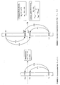
- Figure 4 illustrates how the measurements from receiver pair 16 and transmitter pair 14 can be averaged to produce a compensated resistivity. This process can be accomplished by averaging the dual-transmitter propagation measurements with the dual-receiver propagation measurements and then transforming the average measurements into resistivity, or alternatively, by averaging the resistivities computed from the dual-transmitter measurements with the resistivities computed from the dual-receiver measurements.
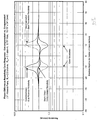
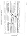
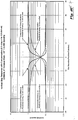
- the compensated apparatus illustrated in Figure 4 also removes vertical response asymmetries typically associated with an uncompensated device. This asymmetry shows up at formation bed boundaries wherein the log of measured resistivity as a function of depth from an uncompensated tool will have a different character as the tool enters a conductive bed, when compared to a log as the tool exits a conductive bed. This effect is illustrated in Figure 6 .
- Receiver and transmitter errors are still present.
- the dual-receiver measurements from receiver pair 16 contain receiver errors and the dual-transmitter measurements from transmitter pair 14 contains transmitter errors, however such errors can be compensated with electronic features incorporated in the design of the apparatus as described later in this document.
- FIG 8 One embodiment of a depth-offset compensated propagation wave resistivity tool 20 is shown in Figure 8 .
- Four parameters can describe the location and layout of the tool 20 antennas. These four parameters are the total number of transmitters (J), the total number of receivers (K), the spacings between upper transmitter TxJ and the lower receiver Rx1 (Z m , n ), and the spacings between adjacent transmitter and receiver antennas.
- Four different tool layout examples are illustrated in Figures 9 through 12 , wherein different combinations of receivers and transmitters are illustrated.
- the transmitters are located below the receivers.
- configurations placing the receivers below the transmitters can be used and will have the same response as a device positioning the transmitters below the receivers. Placement of the transmitters and receivers above or below the other depends on the desired implementation.
- Tool 30 contains a single transmitter circuit 32 that drives one of three different transmitter antennas Tx1 , Tx2, and Tx3 via an electronic switch 34.
- the transmitters are typically selected in sequence under the control of an acquisition routine programmed in acquisition controller and processor 36.
- Three sets of similar receiver electronics 38 acquire the data from the three receiver antennas Rx1 , Rx2, and Rx3 simultaneously.
- a local oscillator provides the frequency references for both the transmitter and receiver mixer circuits 40.
- the receiver signals are passed through low pass filters 42 and then on to a multichannel analog-to-digital converter 44.
- Acquisition controller and processor block 36 directs the sequencing and timing of the acquisition electronics and also acquires and processes the measurement data.
- An interface to accept commands from and pass data to the user is also provided by block 36.
- Such an interface can connect to a telemetry system (not shown) to provide a means to acquire and transmit data in real time such as in the determination of formation resistivity while drilling.
- the electronic errors associated with the transmitters and receivers preferably use an additional compensation method.
- This electronic compensation method involves measuring the transmitter errors directly with an electronic circuit and calculating the receiver errors by depth aligning and comparing equivalent propagation measurements from different transmitter-receiver pairs. This process is illustrated in Figure 14 for a three-transmitter and three-receiver tool.
- the electronic calibration only needs four quantities - the differential propagation measurement error of the two close spaced receiver pairs and the differential propagation measurement error of the two close spaced transmitter pairs.
- these differential propagation measurements are attenuation and phase difference, but this calibration process can also be applied to other measurements.
- a 21 E Tx 2 + P 21 A + E Rx 1 .
- E Tx1 and E Tx2 are the errors associated with transmitters Tx1 and Tx2 respectively and E Rx1 is the error associated with receiver Rx1.
- the dual transmitter propagation measurement for Tx1 and Tx2 using Rx1 can be written as
- the quantity (P21 A - P11 A ) is the differential propagation property to be measured without error. Error associated with receiver Rx1 cancels and the error remaining, (E TX2 - E Tx1 ), is due to transmitters Tx1 and Tx2.
- M TM is the medium-spaced differential propagation measurement. Similar derivations of the short-spaced, M T s and long-spaced, MTL, dual-transmitter propagation measurements can be made.
- the errors in M TS , M TM and M T are all differential transmitter errors.
- differential transmitter errors are directly measured in the tool by sampling the transmitter current 46 and the transmitter voltage 48 and by deriving correction factors for data acquired with each transmitter pair 14.
- Outputs from transmitter sense circuit 50 are treated in a similar fashion to the receiver signals and passed to analog-to-digital converter 44.
- the differential transmitter errors are then calculated by forming the difference of certain characteristics of the sampled transmitter signals. For instance, the differential transmitter phase errors can be calculated from the phase difference of the sampled signals and the differential transmitter attenuation errors can be calculated from the difference of the amplitudes of the sampled transmitter signals. Since these transmitter sense outputs are processed with the same circuits, any systematic errors associated with the acquisition circuits are removed when these differential corrections are calculated. After the differential transmitters errors have been calculated from the sampled transmitter signals such errors can be subtracted from M T s. M TM and M T L to remove errors associated with the transmitter elements of the system.
- the errors in M RS , M RM and M RL are all differential receiver errors.
- the differential receiver errors can be determined with the use of the transmitter error measurements described above and with a process that involves depth aligning and comparing equivalent propagation measurements from different transmitter-receiver pairs.
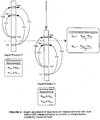
- the tool body has been moved by amount ⁇ Z from depth position A to depth position B.
- a number of propagation paths at position A are equivalent to other propagation paths at position B.
- P11 A is equivalent to P22 B
- P12 A is equivalent to P23 B
- the invention permits determination of all four of the required differential measurement errors, including the two differential-transmitter measurement errors and the two differential-receiver measurement errors.
- the differential-transmitter errors can be subtracted from the appropriate dual-transmitter measurements, M T s, M TM and M IL and the differential-receiver errors from the appropriate dual-receiver measurements, M RS , M R M and M RL , thereby providing propagation measurements free of the errors associated with the transmitter and receiver elements of the system.
- differential errors can be identified, such as the differential receiver error (E RX1 - E RX2 ) derived from the measurements A11 and B22.
- E RX1 - E RX2 differential receiver error
- the controller is capable of producing a compensated resistivity measurement of the geologic formation by averaging uncompensated dual-receiver resistivity measurements with uncompensated dual-transmitter resistivity measurements of the geologic formation taken from two selected locations within the borehole. This averaging provides a compensated resistivity measurement with symmetrical vertical response and reduced effects from borehole rugosity.
- the controller can also be capable of producing a compensated resistivity measurement of the geologic formation by averaging dual-receiver propagation measurements (such as attenuation and phase difference) with dual-transmitter propagation measurements of the geologic formation taken from two selected locations within the borehole. This averaging results in a compensated resistivity measurement with a symmetrical vertical response and reduced effects from borehole rugosity.
- Compensation of errors from the transmitting and receiving elements of the system can be made by measuring currents and voltages generated by first and second transmitters, by measuring currents and voltages of the electrical signals generated by the first and second receivers, and by operating the controller to derive corrections for the transmitter propagation errors from the differences between such current and voltage measurements.
- the controller can be operated to derive receiver propagation errors from the corrections for the transmitter propagation errors and from depth aligned receiver propagation measurements.
- the invention has significant advantages over prior art tools. Such advantages include a shorter tool length, multiple depths of investigation with fewer antennas, compensation for the asymmetrical vertical response of electromagnetic wave tools, compensation for borehole rugosity effects, and compensation for the errors caused by the transmitter and receiver elements of the apparatus.
- compensation of the data acquisition errors associated with the dual-transmitter measurements are removed with electronic circuits that measure the transmitter current and voltage.
- the data acquisition errors associated with the dual-receiver measurements are removed by making use of the electronic transmitter error compensation and by deriving correction factors from the data acquired with each receiver.
- This receiver error compensation process requires, as previously described, a technique of depth alignment of similar propagation measurements to determine errors introduced by the receiver data acquisition electronics.
- a second embodiment which is the preferred embodiment of this application, an apparatus and method to correct, in real time, data acquisition errors of propagation wave devices that use multiple receivers to measure propagation parameters such as attenuation and phase difference, will be described with reference to Figures 15 and 16 .
- This second preferred embodiment does not require the use of depth aligned propagation measurements to remove errors in the dual-receiver measurements introduced by the receiver data acquisition system. This simplifies the correction of receiver element errors and allows these corrections to be performed in real time in a processor downhole.
- FIG. 15 a block diagram of a second preferred propagation wave resistivity device 60 incorporating features that provide for automatic calibration of receiver data acquisition errors will now be described.
- Figure 15 outlines the basic concept of the new receiver calibration scheme.
- a calibration signal is injected via calibration signal injection circuits 62, 64 into the front end of each receiver (Rx1 and Rx2).
- This calibration signal is applied in series with the receiver antennas Rx1 and Rx2 and as a result is electrically added to the received signal.
- Both the received signal and the injected calibration signal are processed with the receiver data acquisition electronics and amplifier 66, 68 respectively. By measuring both the received signal and the calibration signal with the same acquisition electronics, the errors of the acquisition electronics can be eliminated.
- the operation of the resistivity device 60 is similar to the operation of the resistivity tool 30 discussed in relation to Figure 13 .
- the preferred embodiment of Figure 15 depicts a pair of receivers, Rx1 , Rx2, and the calibration signal injection circuits 62, 64.
- the transmitter electronics 70 generates a signal that causes transmitter antenna Tx to generate an electromagnetic propagation wave.
- the transmitter electronics 70 is controlled from the transmitter and calibration signal source means 74. which in turn is controlled by the acquisition controller and processor 76.
- the receivers Rx1 , Rx2 receive the signal that has propagated from the transmitter, Tx. This signal is then communicated to the amplifier and data acquisition electronic means 66, 68, respectively. As noted earlier, the calibration signal injection circuits 62, 64 has injected the calibration signal into the front-ends of receivers Rx1 , Rx2. The data acquisition electronics 66, 68 will measure both the received signal and the calibration signal, which in turn will be communicated to the acquisition controller and processor 76. The acquisition controller and processor 76 will compute the phase difference, and in turn compute resistivity.
- ⁇ Rx1 and ⁇ Rx2 represent the true phase of the received signals from antennas Rx1 and Rx2.
- ⁇ E1 represents the phase errors introduced by the acquisition electronics of Rx1
- ⁇ E2 represent the phase errors introduced by the acquisition electronics of Rx2.
- the measured phase difference, PDuc contains an error term associated with the phase errors introduced by the acquisition electronics of Rx1 and Rx2.
- PDuc is the un-calibrated phase-difference measurement.
- PD is free of the errors associated with the acquisition electronics. Also, the above equation shows how the quantity, ⁇ Ca , cancels out indicating the value of 6> Ca , does not need to be known in order to remove the acquisition electronic errors from the phase difference measurement.
- the same technique can be applied to other propagation measurements.
- the dual-receiver attenuation measurement can be calibrated using the same process.
- the method is identical to the phase-difference calibration method except for the substitution of the signal phases with the corresponding signal amplitude levels expressed in decibels.
- AT A M 1 ⁇ A M 2 ⁇ A M ci ⁇ A MC 2
- AT A Rx 1 ⁇ A Rx 2 + A E 1 ⁇ A E 2 ⁇ A MC 1 ⁇ A MC 2
- the calibration signal can be injected and measured.
- the first is time-multiplexing. If the frequency of the calibration signal is selected to be exactly the same as the frequency of the received signal, the two signals will interfere with each other if the calibration signal is injected when the received signal is present.
- the acquisition controller can overcome signal interference by time-multiplexing the received signal with the calibration signal. This is accomplished by having the acquisition controller sequentially activate the transmitter and then the calibration signal circuits. This provides a time-multiplexed series of received data with calibration data.
- a second method that could be used is frequency domain multiplexing.
- the method separates the calibration signal from the received signal by a small difference in frequency.
- Forcing ⁇ F by the above constraint insures that the received signal can be exactly canceled out while processing the calibration signal and the calibration signal can be exactly canceled out while processing the received signal.
- Making ⁇ F small insures that the acquisition electronic errors that affect the received signal can be accurately measured by the calibration signal.
- ⁇ F can be equal to 10 Hz. This would place the calibration signal at 2.000010 MHz and the received signal at 2.000000 MHz. At this relatively small frequency separation, the electronic errors measured with the calibration signal would accurately reflect the errors introduced into the received signal.
- One important aspect of the apparatus used for the calibration is the differential accuracy of the injected calibration signals. That is, there needs to be very small differences or known and stable differences in the calibration signals injected into each receiver. Any unaccounted differences between the two calibration signals will result in errors in the final propagation measurement. For example, in the case of the phase-difference measurement, the phase of the injected calibration signal into Rx1 has to be equal to the phase of the injected calibration signal into Rx2. If there are any phase differences in the two calibrations signals, these differences must be known and unchanging. As a result, the implementation of the calibration apparatus is important.
- the calibration signals are injected into the receiver front ends of Rx1 , Rx2 using a current loop 78, 80.
- a calibration current source means 86 which is electrically communicated with the transmitter and calibration signal source 74, generates a current, I, that is communicated to current loop 78, 80.
- Current transformers 82, 84 placed in the current loop 78, 80 and located near the front end of the receiver, sample the current in the loop of the respective receivers Rx1/Rx2.
- the sampled current is converted to a small voltage that is added in series with the received signal. Since the amplitude and phase of the current flowing in the current loop is essentially equal at any point in the loop, the calibration signals produced at each receiver will track and minimize any potential differential calibration signal errors.
- the current transformers also provide voltage isolation between receivers and prevent any cross coupling of the receiver signals.
- the invention can be applied to a device with three receivers (as seen in Figure 11 ) by injecting calibration signals into the third receiver in a manner similar to the first two receivers.
- the method could then compute three differential calibration quantities: one for the Rx1/Rx2 pair, one for the Rx2/Rx3 pair and one for the Rx1/Rx3 pair.
- the method could compute calibration quantities for six different pairs, Rx1/Rx2, Rx2/Rx3, Rx3/Rx4, Rx1/Rx3, Rx2/Rx4, and Rx1/Rx4.
Landscapes
- Physics & Mathematics (AREA)
- Life Sciences & Earth Sciences (AREA)
- Engineering & Computer Science (AREA)
- General Life Sciences & Earth Sciences (AREA)
- General Physics & Mathematics (AREA)
- Geophysics (AREA)
- Manufacturing & Machinery (AREA)
- Electromagnetism (AREA)
- Environmental & Geological Engineering (AREA)
- Geology (AREA)
- Remote Sensing (AREA)
- Geophysics And Detection Of Objects (AREA)
Claims (20)
- Verfahren zum Erhalten einer elektromagnetischen Ausbreitungsmessung einer unterirdischen geologischen Formation, wobei die geologische Formation von einem Bohrloch durchschnitten wird, wobei das Verfahren umfasst:- Bereitstellen einer Vorrichtung (60) innerhalb des Bohrlochs, wobei die Vorrichtung (60) umfasst:einen Sender (Tx), der an der Vorrichtung (60) angebracht ist, um ein Signal zu senden;einen ersten Empfänger (Rx1) und einen zweiten Empfänger (Rx2), die an der Vorrichtung (60) angebracht sind, um das gesendete Signal zu empfangen; undein Verarbeitungsmittel (76) zum Verarbeiten der empfangenen Signale;- Erzeugen des Signals von dem Sender (Tx);- Empfangen des gesendeten Signals an dem ersten und zweiten Empfänger (Rx1, Rx2);- Injizieren eines Kalibrierungssignals mit einer Kalibrierungsschaltung (62, 64) in den ersten Empfänger (Rx1) und den zweiten Empfänger (Rx2);- Verarbeiten des Empfängersignals und des Kalibrierungssignals innerhalb des Verarbeitungsmittels (76), wobei der Schritt des Verarbeitens des Empfängersignals und des Kalibrierungssignals ein Berechnen einer datenerfassungsfehlerfreien Phasendifferenz durch Errechnen der Phasendifferenz wie folgt beinhaltet:
 - wobei PD die erfassungsfehlerfreie Phasendifferenz ist;- θM1 die gemessene Phase des nicht kalibrierten Empfängersignals von dem ersten Empfänger (Rx1) ist;- θM2 die gemessene Phase des nicht kalibrierten Empfängersignals von dem zweiten Empfänger (Rx2) ist;- θMC1 die gemessene Phase des Kalibrierungssignals von dem ersten Empfänger (Rx1) ist; und- θMC2 die gemessene Phase des Kalibrierungssignals von dem zweiten Empfänger (Rx2) ist;- Korrigieren von Datenerfassungsfehlern in Bezug auf den ersten Empfänger (Rx1) und den zweiten Empfänger (Rx2);- Bestimmen der elektromagnetischen Ausbreitungsmessung, dadurch gekennzeichnet, dass das Kalibrierungssignal unter Verwendung einer Stromschleife (78, 80) in die Empfänger-Front-Ends injiziert wird, wobei die Stromschleife (78, 80) einen Stromwandler (82, 84) aufweist, der sich darin befindet, und wobei das Verfahren ferner ein Abtasten des Stroms in der Schleife (78, 80) mit einem Stromabtastwiderstand (88, 90) auf dem Stromwandler (82, 84) beinhaltet.
 - Verfahren nach Anspruch 1, wobei der Schritt des Verarbeitens des Empfängersignals und des Kalibrierungssignals ferner ein Berechnen einer datenerfassungsfehlerfreien Dämpfung durch Errechnen der Dämpfung wie folgt beinhaltet:
 - wobei AT die erfassungsfehlerfreie Dämpfung ist, ausgedrückt in Dezibel;- AM1 die gemessene Amplitude, ausgedrückt in Dezibel, des nicht kalibrierten Empfängersignals von dem ersten Empfänger (Rx1) ist;- AM2 die gemessene Amplitude, ausgedrückt in Dezibel, des nicht kalibrierten Empfängersignals von dem zweiten Empfänger (Rx2) ist;- AMC1 die gemessene Amplitude, ausgedrückt in Dezibel, des Kalibrierungssignals von dem ersten Empfänger (Rx1) ist;- AMC2 die gemessene Amplitude, ausgedrückt in Dezibel, des Kalibrierungssignals von dem zweiten Empfänger (Rx2) ist.
 - Verfahren nach Anspruch 1, wobei das Kalibrierungssignal auf einer ersten Frequenz liegt und das empfangene Signal auf der ersten Frequenz liegt und das Verfahren ferner umfasst:- Zeitmultiplexen des Empfängersignals mit dem Kalibrierungssignal.
- Verfahren nach Anspruch 3, wobei der Schritt des Zeitmultiplexens ein fortlaufendes Aktivieren des Senders (Tx) und dann der Kalibrierungsschaltung (62, 64) beinhaltet.
- Verfahren nach Anspruch 1, wobei der Schritt des Injizierens des Kalibrierungssignals ein Trennen des Kalibrierungssignals von dem Empfängersignal durch Bereitstellen einer Differenz der Frequenz mit einer Frequenzbereichsmultiplexschaltung, die betriebsfähig mit dem Verarbeitungsmittel (76) verknüpft ist, beinhaltet.
- Verfahren nach Anspruch 5, wobei die Frequenzdifferenz wie folgt ausgewählt wird:
 wobei ΔF die Frequenzdifferenz ist;N eine ganze Zahl ist;ta das Erfassungszeitintervall ist.
 - Verfahren nach Anspruch 1, wobei der Schritt des Injizierens des Kalibrierungssignals Folgendes beinhaltet:- Hinzufügen des Kalibrierungssignals in Reihe mit dem ersten Empfänger (Rx1) und dem zweiten Empfänger (Rx2).
- Verfahren nach Anspruch 1, wobei die Vorrichtung mit einem dritten Empfänger (Rx3) bereitgestellt wird und wobei das Verfahren ferner das Injizieren des Kalibrierungssignals in den dritten Empfänger (Rx3) umfasst.
- Verfahren nach Anspruch 8, ferner Folgendes umfassend:- Errechnen einer Differentialkalibrierungsmenge für den ersten Empfänger (Rx1) und den zweiten Empfänger (Rx2);- Errechnen der Differentialkalibrierungsmenge für den zweiten Empfänger (Rx2) und den dritten Empfänger (Rx3); und- Errechnen der Differentialkalibrierungsmenge für den ersten Empfänger (Rx1) und den dritten Empfänger (Rx3).
- Vorrichtung (60) zum Erhalten einer elektromagnetischen Ausbreitungsmessung einer unterirdischen geologischen Formation, wobei die unterirdische Formation von einem Bohrloch durchschnitten wird, wobei die Vorrichtung (60) umfasst:- einen Sender (Tx), der an der Vorrichtung gelegen ist, um ein elektromagnetisches Signal zu senden;- einen ersten Empfänger (Rx1) und einen zweiten Empfänger (Rx2), die an der Vorrichtung (60) gelegen sind, um das gesendete elektromagnetische Signal zu empfangen;- Mittel zum Messen und Korrigieren von Fehlern in Bezug auf den Sender (Tx);- Mittel (62, 64) zum Injizieren eines Kalibrierungssignals in den ersten Empfänger (Rx1) und den zweiten Empfänger (Rx2);- Mittel (76) zum Verarbeiten des Empfängersignals und des Kalibrierungssignals, um die elektromagnetische Ausbreitungsmessung zu erhalten, wobei das Verarbeitungsmittel (76) eine Empfängerdatenerfassungsschaltung (66, 68) zum Korrigieren von Datenerfassungsfehlern in Bezug auf den ersten Empfänger (Rx1) und den zweiten Empfänger (Rx2) beinhaltet;- und wobei das Verarbeitungsmittel (76) ferner Mittel zum Errechnen einer fehlerfreien Phasendifferenz wie folgt umfasst:
 - wobei PD die erfassungsfehlerfreie Phasendifferenz ist;- θM1 die gemessene Phase des nicht kalibrierten Empfängersignals von dem ersten Empfänger ist;- θM2 die gemessene Phase des nicht kalibrierten Empfängersignals von dem zweiten Empfänger ist;- θMC1 die gemessene Phase des Kalibrierungssignals von dem ersten Empfänger ist;- θMC2 die gemessene Phase des Kalibrierungssignals von dem zweiten Empfänger ist, dadurch gekennzeichnet, dass das Kalibrierungssignal unter Verwendung einer Stromschleife (78, 80) in die Front-Ends des ersten Empfängers und des zweiten Empfängers injiziert wird, wobei die Stromschleife (78, 80) einen Stromwandler (82, 84) aufweist, der sich darin befindet, und wobei die Vorrichtung (60) ferner Mittel zum Abtasten des Stroms in der Schleife mit einem Stromabtastwiderstand (88, 90) beinhaltet.
 - Vorrichtung (60) nach Anspruch 10, wobei das Signalinjizierungsmittel (62, 64) ein Mittel zum Anwenden des Kalibrierungssignals in Reihe mit dem ersten Empfänger (Rx1) und dem zweiten Empfänger (Rx2) beinhaltet.
- Vorrichtung (60) nach Anspruch 11, wobei die Vorrichtung mit einem dritten Empfänger (Rx3) bereitgestellt wird und wobei die Vorrichtung (60) ferner ein Mittel zum Injizieren des Kalibrierungssignals in den dritten Empfänger (Rx3) umfasst.
- Vorrichtung (60) nach Anspruch 12, ferner umfassend:- Mittel zum Errechnen einer Differentialkalibrierungsmenge für den ersten Empfänger (Rx1) und den zweiten Empfänger (Rx2);- Mittel zum Errechnen der Differentialkalibrierungsmenge für den zweiten Empfänger (Rx2) und den dritten Empfänger (Rx3); und- Mittel zum Errechnen der Differentialkalibrierungsmenge für den ersten Empfänger (Rx1) und den dritten Empfänger (Rx3).
- Vorrichtung (60) nach Anspruch 13, wobei das Verarbeitungsmittel (76) ferner ein Mittel zum Errechnen einer fehlerfreien Dämpfung wie folgt umfasst:
 - wobei AT die erfassungsfehlerfreie Dämpfung ist, ausgedrückt in Dezibel;- AM1 die gemessene Amplitude, ausgedrückt in Dezibel, des nicht kalibrierten Empfängersignals von dem ersten Empfänger ist;- AM2 die gemessene Amplitude, ausgedrückt in Dezibel, des nicht kalibrierten Empfängersignals von dem zweiten Empfänger ist;- AMC1 die gemessene Amplitude, ausgedrückt in Dezibel, des Kalibrierungssignals von dem ersten Empfänger ist;- AMC2 die gemessene Amplitude, ausgedrückt in Dezibel, des Kalibrierungssignals von dem zweiten Empfänger ist.
 - Vorrichtung (60) nach Anspruch 10, wobei das Kalibrierungssignal auf einer ersten Frequenz liegt und das Empfängersignal auf der ersten Frequenz liegt und die Vorrichtung ferner Folgendes umfasst:- Mittel, das betriebsfähig mit dem Verarbeitungsmittel verbunden ist, zum Zeitmultiplexen des nicht kalibrierten Empfängersignal mit dem kalibrierten Signal.
- Vorrichtung (60) nach Anspruch 15, wobei das Zeitmultiplexmittel ein Mittel zum sequentiellen Aktivieren des Senders und des Kalibrierungsinjektionsmittels beinhaltet.
- Vorrichtung (60) nach Anspruch 10, ferner umfassend ein Frequenzbereichsmultiplexmittel, das betriebsfähig mit dem Verarbeitungsmittel verknüpft ist, zum Trennen des Kalibrierungssignals von dem Empfängersignal durch eine Differenz in der Frequenz.
- Vorrichtung (60) nach Anspruch 17, wobei die Frequenzdifferenz des Frequenzbereichsmultiplexmittels wie folgt ausgewählt ist:
 wobei ΔF die Frequenzdifferenz ist;N eine ganze Zahl ist;ta das Erfassungszeitintervall ist.
 - Vorrichtung nach Anspruch 18, wobei das Frequenzbereichsmultiplexmittel das Empfängersignal während der Verarbeitung des Kalibrierungssignals aufhebt und das Kalibrierungssignal während der Verarbeitung des Empfängersignals aufhebt.
- Vorrichtung nach Anspruch 10, wobei das Kalibrierungssignal in Reihe mit dem ersten Empfänger (Rx1) und dem zweiten Empfänger (Rx2) hinzugefügt wird.
Applications Claiming Priority (2)
| Application Number | Priority Date | Filing Date | Title |
|---|---|---|---|
| US10/980,690 US7183771B2 (en) | 2002-09-09 | 2004-11-03 | Multiple transmitter and receiver well logging device with error calibration system including calibration injection system |
| PCT/US2005/038624 WO2006052458A2 (en) | 2004-11-03 | 2005-10-27 | Multiple transmitter and receiver well logging device with error calibration system |
Publications (3)
| Publication Number | Publication Date |
|---|---|
| EP1810058A2 EP1810058A2 (de) | 2007-07-25 |
| EP1810058A4 EP1810058A4 (de) | 2017-03-08 |
| EP1810058B1 true EP1810058B1 (de) | 2019-12-25 |
Family
ID=36336946
Family Applications (1)
| Application Number | Title | Priority Date | Filing Date |
|---|---|---|---|
| EP05823165.5A Expired - Lifetime EP1810058B1 (de) | 2004-11-03 | 2005-10-27 | Mehrfachsende- und empfangs-bohrlochmessungsgerät mit fehlerkalibrierungssystem |
Country Status (5)
| Country | Link |
|---|---|
| US (1) | US7183771B2 (de) |
| EP (1) | EP1810058B1 (de) |
| CN (1) | CN101069105B (de) |
| CA (1) | CA2584585C (de) |
| WO (1) | WO2006052458A2 (de) |
Cited By (1)
| Publication number | Priority date | Publication date | Assignee | Title |
|---|---|---|---|---|
| WO2021258047A1 (en) | 2020-06-19 | 2021-12-23 | Schlumberger Technology Corporation | Antenna calibration in an em logging tool |
Families Citing this family (33)
| Publication number | Priority date | Publication date | Assignee | Title |
|---|---|---|---|---|
| US7408355B1 (en) * | 2004-05-07 | 2008-08-05 | Baker Hughes Incorporated | Borehole conductivity simulator verification and transverse coil balancing |
| US7205770B2 (en) * | 2004-05-07 | 2007-04-17 | Baker Hughes Incorporated | Borehole conductivity simulator verification and transverse coil balancing |
| US7652478B2 (en) * | 2004-05-07 | 2010-01-26 | Baker Hughes Incorporated | Cross-component alignment measurement and calibration |
| US7932723B2 (en) * | 2004-05-07 | 2011-04-26 | Baker Hughes Incorporated | Borehole conductivity simulator verification and transverse coil balancing |
| US7319331B2 (en) * | 2004-05-07 | 2008-01-15 | Baker Hughes Incorporated | Two loop calibrator |
| US7969153B2 (en) * | 2004-05-07 | 2011-06-28 | Baker Hughes Incorporated | Borehole conductivity simulator verification and transverse antenna balancing |
| US7141981B2 (en) * | 2004-07-23 | 2006-11-28 | Baker Hughes Incorporated | Error correction and calibration of a deep reading propagation resistivity tool |
| US7839148B2 (en) * | 2006-04-03 | 2010-11-23 | Halliburton Energy Services, Inc. | Method and system for calibrating downhole tools for drift |
| US7915895B2 (en) * | 2007-06-22 | 2011-03-29 | Baker Hughes Incorporated | Method of calibrating an azimuthal inductive cross-coil or tilted coil instrument |
| US8301384B2 (en) * | 2007-11-29 | 2012-10-30 | Baker Hughes Incorporated | Wellbore logging performance verification method and apparatus |
| EP2154553A1 (de) | 2008-08-12 | 2010-02-17 | Schlumberger Holdings Limited | Verfahren und Vorrichtung zur Messung des Widerstands von Formationen |
| US8497673B2 (en) * | 2009-09-28 | 2013-07-30 | Schlumberger Technology Corporation | Directional resistivity antenna shield |
| US8466682B2 (en) * | 2009-09-29 | 2013-06-18 | Schlumberger Technology Corporation | Apparatus and method for downhole electromagnetic measurement while drilling |
| BR112013003634A2 (pt) * | 2010-08-16 | 2016-09-06 | Halliburton Energy Services Inc | aparelhos para medir sinais indicativos de propriedades no furo descendente e propriedades no furo descendente, método de medir propriedades no furo descendente, e, mídia de armazenamento legível por máquina |
| CN102176062B (zh) * | 2011-02-23 | 2013-05-15 | 北京南风科创应用技术有限公司 | 多功能发射机 |
| US8854045B2 (en) * | 2012-07-11 | 2014-10-07 | Pico Technologies Llc | Electronics for a thin bed array induction logging system |
| BR122015032411A2 (pt) * | 2012-12-31 | 2019-08-27 | Halliburton Energy Services Inc | método para efetuar medições relacionadas à exploração de petróleo e gás, dispositivo de armazenamento legível por máquina tendo instruções nele armazenadas, e, sistema para efetuar medições relacionadas à exploração de petróleo e gás |
| US10139516B2 (en) | 2012-12-31 | 2018-11-27 | Halliburton Energy Services, Inc. | Apparatus and methods to find a position in an underground formation |
| US10203193B2 (en) * | 2012-12-31 | 2019-02-12 | Halliburton Energy Services, Inc. | Apparatus and methods to find a position in an underground formation |
| CA2900806C (en) | 2013-03-11 | 2018-01-02 | Halliburton Energy Services, Inc. | Downhole ranging from multiple wellbores |
| CN103293555A (zh) * | 2013-05-22 | 2013-09-11 | 中国石油集团长城钻探工程有限公司 | 一种地层介电常数和电阻率测量仪器及其使用方法 |
| CA2913964A1 (en) | 2013-07-11 | 2015-01-15 | Halliburton Energy Services, Inc. | Rotationally-independent wellbore ranging |
| US10359536B2 (en) | 2013-09-10 | 2019-07-23 | Halliburton Energy Services Inc. | Surface calibration of a wellbore resistivity logging tool |
| US20150212226A1 (en) * | 2014-01-27 | 2015-07-30 | CNPC USA Corp. | System and method for a downhole logging tool with an array of paired receiver antennas |
| MX2016017265A (es) * | 2014-07-11 | 2017-04-25 | Halliburton Energy Services Inc | Herramientas de inspeccion de tuberias simetricas enfocadas. |
| CN105988045B (zh) * | 2014-11-24 | 2023-04-07 | 中国石油集团长城钻探工程有限公司 | 侧向测井仪中的校准电路 |
| US10082593B2 (en) * | 2016-03-01 | 2018-09-25 | Gowell International, Llc | Method and apparatus for synthetic magnetic sensor aperture using eddy current time transient measurement for downhole applications |
| WO2018044337A1 (en) * | 2016-09-02 | 2018-03-08 | Halliburton Energy Services, Inc. | In-situ gain/phase calibration and characterization of downhole receiver electronics |
| US11306577B2 (en) * | 2017-06-08 | 2022-04-19 | Halliburton Energy Services, Inc. | Calibrating electromagnetic corrosion detection tools via core saturation |
| US11774633B2 (en) * | 2018-06-05 | 2023-10-03 | Schlumberger Technology Corporation | Method to automatically calibrate a downhole tool in an oil-based mud environment |
| WO2020154629A1 (en) * | 2019-01-24 | 2020-07-30 | Baker Hughes Oilfield Operations Llc | Two-way dual-tone methods and systems for synchronizing remote modules |
| US12345847B2 (en) | 2022-05-23 | 2025-07-01 | Baker Hughes Oilfield Operations Llc | Downhole logging using symmetric and asymmetric compensated resistivity measurements |
| CN116856920B (zh) * | 2023-07-06 | 2024-04-02 | 中国科学院地质与地球物理研究所 | 一种随钻方位电磁波电阻率仪器使用方法及仪器 |
Family Cites Families (20)
| Publication number | Priority date | Publication date | Assignee | Title |
|---|---|---|---|---|
| US4609873A (en) | 1980-01-04 | 1986-09-02 | Texaco Inc. | Dielectric well logging system with at least three transmitter coils and at least two receiver coils for determining resistivity and dielectric constant of a subsurface formation adjacent a fluid invaded zone of the formation |
| US4451789A (en) | 1981-09-28 | 1984-05-29 | Nl Industries, Inc. | Logging tool and method for measuring resistivity of different radial zones at a common depth of measurement |
| US4613821A (en) * | 1983-01-10 | 1986-09-23 | Conoco Inc. | Method and apparatus for obtaining high accuracy simultaneous calibration of signal measuring systems |
| AU580077B2 (en) * | 1985-04-03 | 1988-12-22 | Stolar, Inc. | Electromagnetic instruments and survey procedures for imaging structure in coal seams |
| US4968940A (en) | 1987-10-30 | 1990-11-06 | Schlumberger Technology Corporation | Well logging apparatus and method using two spaced apart transmitters with two receivers located between the transmitters |
| US4949045A (en) | 1987-10-30 | 1990-08-14 | Schlumberger Technology Corporation | Well logging apparatus having a cylindrical housing with antennas formed in recesses and covered with a waterproof rubber layer |
| US5001675A (en) | 1989-09-13 | 1991-03-19 | Teleco Oilfield Services Inc. | Phase and amplitude calibration system for electromagnetic propagation based earth formation evaluation instruments |
| US5260660A (en) * | 1990-01-17 | 1993-11-09 | Stolar, Inc. | Method for calibrating a downhole receiver used in electromagnetic instrumentation for detecting an underground conductor |
| US5811972A (en) * | 1991-04-29 | 1998-09-22 | Baker Hughes Incorporated | Method and apparatus for determining influence of mutual magnetic coupling in electromagnetic propagation tools |
| US5594343A (en) | 1994-12-02 | 1997-01-14 | Schlumberger Technology Corporation | Well logging apparatus and method with borehole compensation including multiple transmitting antennas asymmetrically disposed about a pair of receiving antennas |
| US6476609B1 (en) | 1999-01-28 | 2002-11-05 | Dresser Industries, Inc. | Electromagnetic wave resistivity tool having a tilted antenna for geosteering within a desired payzone |
| US6184685B1 (en) | 1999-02-22 | 2001-02-06 | Halliburton Energy Services, Inc. | Mulitiple spacing resistivity measurements with receiver arrays |
| US6218842B1 (en) * | 1999-08-04 | 2001-04-17 | Halliburton Energy Services, Inc. | Multi-frequency electromagnetic wave resistivity tool with improved calibration measurement |
| US6304086B1 (en) | 1999-09-07 | 2001-10-16 | Schlumberger Technology Corporation | Method and apparatus for evaluating the resistivity of formations with high dip angles or high-contrast thin layers |
| US6353321B1 (en) | 2000-01-27 | 2002-03-05 | Halliburton Energy Services, Inc. | Uncompensated electromagnetic wave resistivity tool for bed boundary detection and invasion profiling |
| US6603312B2 (en) * | 2000-12-11 | 2003-08-05 | Cbg Corporation | Multi-frequency array induction tool |
| US6538447B2 (en) | 2000-12-13 | 2003-03-25 | Halliburton Energy Services, Inc. | Compensated multi-mode elctromagnetic wave resistivity tool |
| US6541979B2 (en) | 2000-12-19 | 2003-04-01 | Schlumberger Technology Corporation | Multi-coil electromagnetic focusing methods and apparatus to reduce borehole eccentricity effects |
| US6822455B2 (en) * | 2002-09-09 | 2004-11-23 | Ultima Labs, Inc. | Multiple transmitter and receiver well logging system and method to compensate for response symmetry and borehole rugosity effects |
| US7141981B2 (en) * | 2004-07-23 | 2006-11-28 | Baker Hughes Incorporated | Error correction and calibration of a deep reading propagation resistivity tool |
-
2004
- 2004-11-03 US US10/980,690 patent/US7183771B2/en not_active Expired - Lifetime
-
2005
- 2005-10-27 CN CN2005800378368A patent/CN101069105B/zh not_active Expired - Fee Related
- 2005-10-27 CA CA2584585A patent/CA2584585C/en not_active Expired - Fee Related
- 2005-10-27 WO PCT/US2005/038624 patent/WO2006052458A2/en not_active Ceased
- 2005-10-27 EP EP05823165.5A patent/EP1810058B1/de not_active Expired - Lifetime
Non-Patent Citations (1)
| Title |
|---|
| None * |
Cited By (3)
| Publication number | Priority date | Publication date | Assignee | Title |
|---|---|---|---|---|
| WO2021258047A1 (en) | 2020-06-19 | 2021-12-23 | Schlumberger Technology Corporation | Antenna calibration in an em logging tool |
| EP4168830A4 (de) * | 2020-06-19 | 2024-07-17 | Services Pétroliers Schlumberger | Antennenkalibrierung in einem em-protokollierungswerkzeug |
| US12222461B2 (en) | 2020-06-19 | 2025-02-11 | Schlumberger Technology Corporation | Antenna calibration in an EM logging tool |
Also Published As
| Publication number | Publication date |
|---|---|
| WO2006052458A2 (en) | 2006-05-18 |
| EP1810058A4 (de) | 2017-03-08 |
| US20050088180A1 (en) | 2005-04-28 |
| US7183771B2 (en) | 2007-02-27 |
| CN101069105B (zh) | 2011-04-06 |
| CA2584585A1 (en) | 2006-05-18 |
| EP1810058A2 (de) | 2007-07-25 |
| CA2584585C (en) | 2015-01-06 |
| HK1108489A1 (en) | 2008-05-09 |
| CN101069105A (zh) | 2007-11-07 |
| WO2006052458A3 (en) | 2006-07-06 |
Similar Documents
| Publication | Publication Date | Title |
|---|---|---|
| EP1810058B1 (de) | Mehrfachsende- und empfangs-bohrlochmessungsgerät mit fehlerkalibrierungssystem | |
| CA2357340C (en) | Wellbore resistivity tool with simultaneous multiple frequencies | |
| US7095232B2 (en) | Determination of borehole geometry inside cased wells with crosswell electromagnetics | |
| EP2015109A1 (de) | Werkzeug zur Bewertung einer Bohrlochformierung | |
| EP1155343B1 (de) | Gerät zur widerstandsmessung unter verwendung elektromagnetischer wellen und einer geneigten antenne | |
| US6574562B2 (en) | Determination of formation anisotropy using multi-frequency processing of induction measurements with transverse induction coils | |
| EP2220518B1 (de) | Verfahren und vorrichtung zur elektromagnetischen erfassung einer formation | |
| US6308136B1 (en) | Method of interpreting induction logs in horizontal wells | |
| US20100305862A1 (en) | Borehole compensated resistivity logging tool having an asymmetric antenna spacing | |
| EP1373937A1 (de) | 2d-inversion von mehrkomponenten-induktionsprotokollierungsdaten zur auflösung einer anisotropen spezifischen widerstandsstruktur | |
| US10711598B2 (en) | Methods to synchronize signals among antennas with different clock systems | |
| EP1242963B1 (de) | Interferometrisches verarbeitungsverfahren zur erkennung von schichtgrenzen | |
| US7973532B2 (en) | Downhole spread spectrum induction instruments | |
| US6822455B2 (en) | Multiple transmitter and receiver well logging system and method to compensate for response symmetry and borehole rugosity effects | |
| EP0665447B1 (de) | Eliminierungsverfahren von elektromagnetischen Kopplungseffekte in einem Empfängerpaar | |
| US20140132420A1 (en) | Apparatus and Method for Multi-Mode and Multi-Depth Resistivity Measurements | |
| US9354347B2 (en) | Method and apparatus for deep transient resistivity measurement while drilling | |
| US20140136114A1 (en) | Apparatus and Method for Formation Resistivity Measurements | |
| HK1108489B (en) | Multiple transmitter and receiver well logging device with error calibration system | |
| EP0872744A2 (de) | Leitfähigkeitsbestimmung von unterirdischen Lagerstätten |
Legal Events
| Date | Code | Title | Description |
|---|---|---|---|
| PUAI | Public reference made under article 153(3) epc to a published international application that has entered the european phase |
Free format text: ORIGINAL CODE: 0009012 |
|
| 17P | Request for examination filed |
Effective date: 20070601 |
|
| AK | Designated contracting states |
Kind code of ref document: A2 Designated state(s): AT BE BG CH CY CZ DE DK EE ES FI FR GB GR HU IE IS IT LI LT LU LV MC NL PL PT RO SE SI SK TR |
|
| DAX | Request for extension of the european patent (deleted) | ||
| RAP1 | Party data changed (applicant data changed or rights of an application transferred) |
Owner name: SONDEX LIMITED |
|
| RIN1 | Information on inventor provided before grant (corrected) |
Inventor name: SONDEX LIMITED |
|
| REG | Reference to a national code |
Ref country code: DE Ref legal event code: R079 Ref document number: 602005056508 Country of ref document: DE Free format text: PREVIOUS MAIN CLASS: G01V0003080000 Ipc: G01V0003300000 |
|
| A4 | Supplementary search report drawn up and despatched |
Effective date: 20170203 |
|
| RIC1 | Information provided on ipc code assigned before grant |
Ipc: G01V 13/00 20060101ALI20170130BHEP Ipc: G01V 3/30 20060101AFI20170130BHEP |
|
| STAA | Information on the status of an ep patent application or granted ep patent |
Free format text: STATUS: EXAMINATION IS IN PROGRESS |
|
| 17Q | First examination report despatched |
Effective date: 20180326 |
|
| GRAP | Despatch of communication of intention to grant a patent |
Free format text: ORIGINAL CODE: EPIDOSNIGR1 |
|
| STAA | Information on the status of an ep patent application or granted ep patent |
Free format text: STATUS: GRANT OF PATENT IS INTENDED |
|
| INTG | Intention to grant announced |
Effective date: 20190617 |
|
| RIN1 | Information on inventor provided before grant (corrected) |
Inventor name: FLANAGAN, WILLIAM D. |
|
| GRAS | Grant fee paid |
Free format text: ORIGINAL CODE: EPIDOSNIGR3 |
|
| GRAJ | Information related to disapproval of communication of intention to grant by the applicant or resumption of examination proceedings by the epo deleted |
Free format text: ORIGINAL CODE: EPIDOSDIGR1 |
|
| GRAL | Information related to payment of fee for publishing/printing deleted |
Free format text: ORIGINAL CODE: EPIDOSDIGR3 |
|
| STAA | Information on the status of an ep patent application or granted ep patent |
Free format text: STATUS: EXAMINATION IS IN PROGRESS |
|
| GRAR | Information related to intention to grant a patent recorded |
Free format text: ORIGINAL CODE: EPIDOSNIGR71 |
|
| STAA | Information on the status of an ep patent application or granted ep patent |
Free format text: STATUS: GRANT OF PATENT IS INTENDED |
|
| RAP1 | Party data changed (applicant data changed or rights of an application transferred) |
Owner name: PRIME DOWNHOLE MANUFACTURING LLC |
|
| GRAA | (expected) grant |
Free format text: ORIGINAL CODE: 0009210 |
|
| STAA | Information on the status of an ep patent application or granted ep patent |
Free format text: STATUS: THE PATENT HAS BEEN GRANTED |
|
| INTC | Intention to grant announced (deleted) | ||
| AK | Designated contracting states |
Kind code of ref document: B1 Designated state(s): AT BE BG CH CY CZ DE DK EE ES FI FR GB GR HU IE IS IT LI LT LU LV MC NL PL PT RO SE SI SK TR |
|
| INTG | Intention to grant announced |
Effective date: 20191119 |
|
| REG | Reference to a national code |
Ref country code: GB Ref legal event code: FG4D |
|
| REG | Reference to a national code |
Ref country code: CH Ref legal event code: EP |
|
| REG | Reference to a national code |
Ref country code: DE Ref legal event code: R096 Ref document number: 602005056508 Country of ref document: DE |
|
| REG | Reference to a national code |
Ref country code: AT Ref legal event code: REF Ref document number: 1217744 Country of ref document: AT Kind code of ref document: T Effective date: 20200115 |
|
| REG | Reference to a national code |
Ref country code: IE Ref legal event code: FG4D |
|
| REG | Reference to a national code |
Ref country code: NL Ref legal event code: MP Effective date: 20191225 |
|
| PG25 | Lapsed in a contracting state [announced via postgrant information from national office to epo] |
Ref country code: LV Free format text: LAPSE BECAUSE OF FAILURE TO SUBMIT A TRANSLATION OF THE DESCRIPTION OR TO PAY THE FEE WITHIN THE PRESCRIBED TIME-LIMIT Effective date: 20191225 Ref country code: SE Free format text: LAPSE BECAUSE OF FAILURE TO SUBMIT A TRANSLATION OF THE DESCRIPTION OR TO PAY THE FEE WITHIN THE PRESCRIBED TIME-LIMIT Effective date: 20191225 Ref country code: LT Free format text: LAPSE BECAUSE OF FAILURE TO SUBMIT A TRANSLATION OF THE DESCRIPTION OR TO PAY THE FEE WITHIN THE PRESCRIBED TIME-LIMIT Effective date: 20191225 Ref country code: GR Free format text: LAPSE BECAUSE OF FAILURE TO SUBMIT A TRANSLATION OF THE DESCRIPTION OR TO PAY THE FEE WITHIN THE PRESCRIBED TIME-LIMIT Effective date: 20200326 Ref country code: BG Free format text: LAPSE BECAUSE OF FAILURE TO SUBMIT A TRANSLATION OF THE DESCRIPTION OR TO PAY THE FEE WITHIN THE PRESCRIBED TIME-LIMIT Effective date: 20200325 Ref country code: FI Free format text: LAPSE BECAUSE OF FAILURE TO SUBMIT A TRANSLATION OF THE DESCRIPTION OR TO PAY THE FEE WITHIN THE PRESCRIBED TIME-LIMIT Effective date: 20191225 |
|
| REG | Reference to a national code |
Ref country code: LT Ref legal event code: MG4D |
|
| PG25 | Lapsed in a contracting state [announced via postgrant information from national office to epo] |
Ref country code: NL Free format text: LAPSE BECAUSE OF FAILURE TO SUBMIT A TRANSLATION OF THE DESCRIPTION OR TO PAY THE FEE WITHIN THE PRESCRIBED TIME-LIMIT Effective date: 20191225 Ref country code: RO Free format text: LAPSE BECAUSE OF FAILURE TO SUBMIT A TRANSLATION OF THE DESCRIPTION OR TO PAY THE FEE WITHIN THE PRESCRIBED TIME-LIMIT Effective date: 20191225 Ref country code: EE Free format text: LAPSE BECAUSE OF FAILURE TO SUBMIT A TRANSLATION OF THE DESCRIPTION OR TO PAY THE FEE WITHIN THE PRESCRIBED TIME-LIMIT Effective date: 20191225 Ref country code: CZ Free format text: LAPSE BECAUSE OF FAILURE TO SUBMIT A TRANSLATION OF THE DESCRIPTION OR TO PAY THE FEE WITHIN THE PRESCRIBED TIME-LIMIT Effective date: 20191225 Ref country code: PT Free format text: LAPSE BECAUSE OF FAILURE TO SUBMIT A TRANSLATION OF THE DESCRIPTION OR TO PAY THE FEE WITHIN THE PRESCRIBED TIME-LIMIT Effective date: 20200520 |
|
| PG25 | Lapsed in a contracting state [announced via postgrant information from national office to epo] |
Ref country code: SK Free format text: LAPSE BECAUSE OF FAILURE TO SUBMIT A TRANSLATION OF THE DESCRIPTION OR TO PAY THE FEE WITHIN THE PRESCRIBED TIME-LIMIT Effective date: 20191225 Ref country code: IS Free format text: LAPSE BECAUSE OF FAILURE TO SUBMIT A TRANSLATION OF THE DESCRIPTION OR TO PAY THE FEE WITHIN THE PRESCRIBED TIME-LIMIT Effective date: 20200425 |
|
| REG | Reference to a national code |
Ref country code: DE Ref legal event code: R097 Ref document number: 602005056508 Country of ref document: DE |
|
| PG25 | Lapsed in a contracting state [announced via postgrant information from national office to epo] |
Ref country code: DK Free format text: LAPSE BECAUSE OF FAILURE TO SUBMIT A TRANSLATION OF THE DESCRIPTION OR TO PAY THE FEE WITHIN THE PRESCRIBED TIME-LIMIT Effective date: 20191225 Ref country code: ES Free format text: LAPSE BECAUSE OF FAILURE TO SUBMIT A TRANSLATION OF THE DESCRIPTION OR TO PAY THE FEE WITHIN THE PRESCRIBED TIME-LIMIT Effective date: 20191225 |
|
| PLBE | No opposition filed within time limit |
Free format text: ORIGINAL CODE: 0009261 |
|
| STAA | Information on the status of an ep patent application or granted ep patent |
Free format text: STATUS: NO OPPOSITION FILED WITHIN TIME LIMIT |
|
| REG | Reference to a national code |
Ref country code: AT Ref legal event code: MK05 Ref document number: 1217744 Country of ref document: AT Kind code of ref document: T Effective date: 20191225 |
|
| PG25 | Lapsed in a contracting state [announced via postgrant information from national office to epo] |
Ref country code: SI Free format text: LAPSE BECAUSE OF FAILURE TO SUBMIT A TRANSLATION OF THE DESCRIPTION OR TO PAY THE FEE WITHIN THE PRESCRIBED TIME-LIMIT Effective date: 20191225 |
|
| 26N | No opposition filed |
Effective date: 20200928 |
|
| PG25 | Lapsed in a contracting state [announced via postgrant information from national office to epo] |
Ref country code: AT Free format text: LAPSE BECAUSE OF FAILURE TO SUBMIT A TRANSLATION OF THE DESCRIPTION OR TO PAY THE FEE WITHIN THE PRESCRIBED TIME-LIMIT Effective date: 20191225 Ref country code: IT Free format text: LAPSE BECAUSE OF FAILURE TO SUBMIT A TRANSLATION OF THE DESCRIPTION OR TO PAY THE FEE WITHIN THE PRESCRIBED TIME-LIMIT Effective date: 20191225 |
|
| PG25 | Lapsed in a contracting state [announced via postgrant information from national office to epo] |
Ref country code: PL Free format text: LAPSE BECAUSE OF FAILURE TO SUBMIT A TRANSLATION OF THE DESCRIPTION OR TO PAY THE FEE WITHIN THE PRESCRIBED TIME-LIMIT Effective date: 20191225 |
|
| REG | Reference to a national code |
Ref country code: CH Ref legal event code: PL |
|
| PG25 | Lapsed in a contracting state [announced via postgrant information from national office to epo] |
Ref country code: MC Free format text: LAPSE BECAUSE OF FAILURE TO SUBMIT A TRANSLATION OF THE DESCRIPTION OR TO PAY THE FEE WITHIN THE PRESCRIBED TIME-LIMIT Effective date: 20191225 Ref country code: LU Free format text: LAPSE BECAUSE OF NON-PAYMENT OF DUE FEES Effective date: 20201027 |
|
| REG | Reference to a national code |
Ref country code: BE Ref legal event code: MM Effective date: 20201031 |
|
| PG25 | Lapsed in a contracting state [announced via postgrant information from national office to epo] |
Ref country code: FR Free format text: LAPSE BECAUSE OF NON-PAYMENT OF DUE FEES Effective date: 20201031 |
|
| PG25 | Lapsed in a contracting state [announced via postgrant information from national office to epo] |
Ref country code: LI Free format text: LAPSE BECAUSE OF NON-PAYMENT OF DUE FEES Effective date: 20201031 Ref country code: CH Free format text: LAPSE BECAUSE OF NON-PAYMENT OF DUE FEES Effective date: 20201031 Ref country code: BE Free format text: LAPSE BECAUSE OF NON-PAYMENT OF DUE FEES Effective date: 20201031 |
|
| PG25 | Lapsed in a contracting state [announced via postgrant information from national office to epo] |
Ref country code: IE Free format text: LAPSE BECAUSE OF NON-PAYMENT OF DUE FEES Effective date: 20201027 |
|
| PGFP | Annual fee paid to national office [announced via postgrant information from national office to epo] |
Ref country code: GB Payment date: 20211007 Year of fee payment: 17 Ref country code: DE Payment date: 20211005 Year of fee payment: 17 |
|
| PG25 | Lapsed in a contracting state [announced via postgrant information from national office to epo] |
Ref country code: CY Free format text: LAPSE BECAUSE OF FAILURE TO SUBMIT A TRANSLATION OF THE DESCRIPTION OR TO PAY THE FEE WITHIN THE PRESCRIBED TIME-LIMIT Effective date: 20191225 |
|
| REG | Reference to a national code |
Ref country code: DE Ref legal event code: R119 Ref document number: 602005056508 Country of ref document: DE |
|
| GBPC | Gb: european patent ceased through non-payment of renewal fee |
Effective date: 20221027 |
|
| PG25 | Lapsed in a contracting state [announced via postgrant information from national office to epo] |
Ref country code: DE Free format text: LAPSE BECAUSE OF NON-PAYMENT OF DUE FEES Effective date: 20230503 |
|
| PG25 | Lapsed in a contracting state [announced via postgrant information from national office to epo] |
Ref country code: GB Free format text: LAPSE BECAUSE OF NON-PAYMENT OF DUE FEES Effective date: 20221027 |
|
| PG25 | Lapsed in a contracting state [announced via postgrant information from national office to epo] |
Ref country code: TR Free format text: LAPSE BECAUSE OF NON-PAYMENT OF DUE FEES Effective date: 20201027 |