EP1810096B1 - Verfahren zum austauschen von daten zwischen teilnehmern aus verschiedenen netzwerken - Google Patents
Verfahren zum austauschen von daten zwischen teilnehmern aus verschiedenen netzwerken Download PDFInfo
- Publication number
- EP1810096B1 EP1810096B1 EP05797789A EP05797789A EP1810096B1 EP 1810096 B1 EP1810096 B1 EP 1810096B1 EP 05797789 A EP05797789 A EP 05797789A EP 05797789 A EP05797789 A EP 05797789A EP 1810096 B1 EP1810096 B1 EP 1810096B1
- Authority
- EP
- European Patent Office
- Prior art keywords
- time
- real
- networks
- data
- compatible
- Prior art date
- Legal status (The legal status is an assumption and is not a legal conclusion. Google has not performed a legal analysis and makes no representation as to the accuracy of the status listed.)
- Expired - Lifetime
Links
Images


Classifications
-
- H—ELECTRICITY
- H04—ELECTRIC COMMUNICATION TECHNIQUE
- H04L—TRANSMISSION OF DIGITAL INFORMATION, e.g. TELEGRAPHIC COMMUNICATION
- H04L12/00—Data switching networks
- H04L12/28—Data switching networks characterised by path configuration, e.g. LAN [Local Area Networks] or WAN [Wide Area Networks]
- H04L12/40—Bus networks
- H04L12/40006—Architecture of a communication node
- H04L12/40039—Details regarding the setting of the power status of a node according to activity on the bus
-
- G—PHYSICS
- G05—CONTROLLING; REGULATING
- G05B—CONTROL OR REGULATING SYSTEMS IN GENERAL; FUNCTIONAL ELEMENTS OF SUCH SYSTEMS; MONITORING OR TESTING ARRANGEMENTS FOR SUCH SYSTEMS OR ELEMENTS
- G05B19/00—Program-control systems
- G05B19/02—Program-control systems electric
- G05B19/418—Total factory control, i.e. centrally controlling a plurality of machines, e.g. direct or distributed numerical control [DNC], flexible manufacturing systems [FMS], integrated manufacturing systems [IMS] or computer integrated manufacturing [CIM]
- G05B19/4185—Total factory control, i.e. centrally controlling a plurality of machines, e.g. direct or distributed numerical control [DNC], flexible manufacturing systems [FMS], integrated manufacturing systems [IMS] or computer integrated manufacturing [CIM] characterised by the network communication
-
- Y—GENERAL TAGGING OF NEW TECHNOLOGICAL DEVELOPMENTS; GENERAL TAGGING OF CROSS-SECTIONAL TECHNOLOGIES SPANNING OVER SEVERAL SECTIONS OF THE IPC; TECHNICAL SUBJECTS COVERED BY FORMER USPC CROSS-REFERENCE ART COLLECTIONS [XRACs] AND DIGESTS
- Y02—TECHNOLOGIES OR APPLICATIONS FOR MITIGATION OR ADAPTATION AGAINST CLIMATE CHANGE
- Y02D—CLIMATE CHANGE MITIGATION TECHNOLOGIES IN INFORMATION AND COMMUNICATION TECHNOLOGIES [ICT], I.E. INFORMATION AND COMMUNICATION TECHNOLOGIES AIMING AT THE REDUCTION OF THEIR OWN ENERGY USE
- Y02D30/00—Reducing energy consumption in communication networks
- Y02D30/50—Reducing energy consumption in communication networks in wire-line communication networks, e.g. low power modes or reduced link rate
-
- Y—GENERAL TAGGING OF NEW TECHNOLOGICAL DEVELOPMENTS; GENERAL TAGGING OF CROSS-SECTIONAL TECHNOLOGIES SPANNING OVER SEVERAL SECTIONS OF THE IPC; TECHNICAL SUBJECTS COVERED BY FORMER USPC CROSS-REFERENCE ART COLLECTIONS [XRACs] AND DIGESTS
- Y02—TECHNOLOGIES OR APPLICATIONS FOR MITIGATION OR ADAPTATION AGAINST CLIMATE CHANGE
- Y02P—CLIMATE CHANGE MITIGATION TECHNOLOGIES IN THE PRODUCTION OR PROCESSING OF GOODS
- Y02P90/00—Enabling technologies with a potential contribution to greenhouse gas [GHG] emissions mitigation
- Y02P90/02—Total factory control, e.g. smart factories, flexible manufacturing systems [FMS] or integrated manufacturing systems [IMS]
Definitions
- the invention relates to a method for exchanging data between subscribers or nodes from real-time capable and non-real-time capable networks, a device for carrying out this method, a corresponding computer program and a computer program product.
- real-time capable networks have a deterministic time response. This makes it possible to transmit data periodically and within certain time intervals, as is necessary, for example, for samples in a control system.
- non-real-time-capable networks for example Ethernet networks to which computers are connected
- real-time-capable networks for example industrial fieldbuses.
- the non-real-time networks often serve as superimposed systems that provide the control, control, diagnostics, etc. of the subordinate, real-time capable networks or systems.
- decentrally acquired data eg diagnostic information, data sampling, etc.
- the time stamp varies with the transmission time of the data or with the speed of detection of an occurred diagnostic event.
- the time bases of the individual subordinate systems are set by a higher-level system.
- the distributed time base is inaccurate or asynchronous due to the transmission time of the time information.
- WO 03/060617 A1 For example, a measurement network comprising a number of real-time measurement bus systems connected via a non-real-time network is shown.
- the measuring bus systems are provided in addition to the drive bus systems. Measurement data from the different measurement bus systems are correlated by adding timestamps to the measurement data.
- a common timebase for the measurement bus systems is provided by each receiving a GPS head in a measurement bus system. This solution is very expensive.
- Equally difficult to provide is the linking or combination of simultaneous events occurring at different subscribers at a central location if that location is in a non-real-time network.
- this link serves as a trigger for triggering a process in the higher-level system or as a trigger for different subscribers of the lower-level systems
- the difficulty is that simultaneously occurring events in different subordinate networks are not recognized simultaneously in the higher-level system and are related to one another can be.
- the present invention proposes a method for exchanging data between subscribers from different networks and furthermore an apparatus using this method according to the independent patent claims.
- Advantageous embodiments emerge from the respective subclaims and the following description.
- At least two of the real-time capable ones are Networks synchronous to each other. This makes it easy to put the data from the time-synchronous networks into temporal relationship with each other.
- the data provided with a time stamp is transmitted to a subscriber of a non-real-time capable network.
- This participant thus receives the simple possibility of processing or evaluating the data received on a time basis.
- the method according to the invention is used in automation systems, in particular motion control systems and numerical control systems.
- the application of the described method allows real-time data acquisition across controllers or participants. This may be, for example, long-term acquired diagnostic data, which are set in chronological relation to one another, or, for example, process data for troubleshooting by means of logic analysis or oscilloscope functions acquired at short notice.
- trigger signals of different subscribers are combined or linked. This association can be accomplished, for example, by the well-known logical operators (AND, OR, etc.) or in some other way. This allows the monitoring of cross-network events.
- the combination of the trigger signals is transmitted as a new trigger signal to subscribers, in particular from different networks. This makes it easy to use the combination of occurring events to trigger any predeterminable workflows.
- the method according to the invention is particularly preferably used in automation systems, in particular motion control systems and numerical control systems. For the first time, this allows the advantageous combination of trigger events, which encompasses both control and participants.
- a device for exchanging data between nodes or nodes of real-time capable and non-real-time capable networks with means for adding timestamps to data generated in a real-time capable network and means for providing a time synchrony of real time networks is proposed.
- the device according to the invention also has means for carrying out further method steps according to a preferred embodiment of the method according to the invention.
- the device advantageously has means for combining or linking trigger signals of different subscribers, in particular from different networks. This device can also be easily added to existing networks.
- a device according to the invention is used in automation systems, in particular motion control systems and numerical control systems.
- FIG. 1 is a composite of different networks called 100 in total.
- a superimposed non real-time capable network 110 is connected to three subordinate real time capable networks 120, 130, 140.
- the three real-time capable networks 120, 130, 140 have a common time base that is synchronized via a real-time communication link 101, 101 '.
- the non-real-time network 110 has a subscriber 111, for example a PC.
- the real-time capable networks 120, 130, 140 are designed as control systems. They each have a controller or PLC 121, 131, 141, to the other participants 122, 123; 132, 133; 142, 143, for example, sensors or actuators, are connected via real-time connections.
- the triggering of the three subordinate systems is now desired in order to query diagnostic data.
- the PC 111 sends the trigger signal to the controllers 121, 131, 141 via the non-real-time capable network 110. Because of the non real-time capable connection the duration of the signals is undetermined until the controllers are reached.
- this controller 121, 131, 141 begins to record the data. Since the running time of the trigger signals from the PC 111 to the controllers 121, 131, 141 is different, the start time of the data recording is also different.
- the controllers 121, 131, 141 now provide their data, for example at the beginning of the measurement, with a valid time stamp 124, 134, 144. Since the time sequence of a measurement, in the present example a measurement over ten time units, is known, the time stamp 124, 134, 144 may also be added at any other time, for example at the end or in the middle of the measurement. It is understood that a timestamp could also be added to the data at any time unit.
- the transit times between the individual subscribers 121, 122, 123; 131, 132, 133; 141, 142, 143 within a network 120, 130, 140 are determined and known.
- the runtime between the individual subscribers is exactly one time unit.
- FIG. 2 is the result of in FIG. 1 shown method.
- a recording time of ten time units was chosen.
- the trigger signals are sent to the controllers 121, 131, 141.
- one set of data 221, 231, 241 is delivered over time t by the three controllers.
- Each record contains at least one timestamp. For this Timestamp is the start time and the end time of the measurement.
- the data set 221 of the first controller 121 starts at time 0.15 time units and ends at time 10.15 time units.
- the data set 231 of the second controller 131 starts at time 2.73 time units and ends at time 12.73 time units.
- the data set 241 of the third controller 141 starts at 3.94 time units and ends at 13.94 time units.
- the deterministic timestamps allow to establish a temporal relationship between the individual datasets. From the example presented, an overlapping time interval 260 between the times 3.94 time units and 10.15 time units can be determined. During this time interval 260, the measurements in the various underlying networks were performed simultaneously. This time interval 260 can advantageously be used to evaluate the data.
- FIG. 3 shows a further preferred embodiment of the method according to the invention.
- a composite of different networks is designated 100 in total.
- a superimposed non real-time capable network 110 is connected to three subordinate real time capable networks 120, 130, 140.
- the three real-time capable networks 120, 130, 140 have a common time base that is synchronized over the real time communication link 101, 101 '.
- the non-real-time network 110 has a subscriber 111, for example a PC.
- the real-time capable networks 120, 130, 140 are designed as control systems. They each have a controller or PLC 121, 131, 141, to the other participants 122, 123; 132, 133; 142, 143, for example, sensors or actuators, are connected via real-time connections.
- the PC 111 may now establish a relationship when multiple trigger events occur in the various networks 120, 130, 140 and determine the occurrence of the predetermined linked trigger condition.
- the trigger event can be provided with a time stamp and reported to the PC 111.
Landscapes
- Engineering & Computer Science (AREA)
- Computer Networks & Wireless Communication (AREA)
- Signal Processing (AREA)
- General Engineering & Computer Science (AREA)
- Manufacturing & Machinery (AREA)
- Quality & Reliability (AREA)
- Physics & Mathematics (AREA)
- General Physics & Mathematics (AREA)
- Automation & Control Theory (AREA)
- Synchronisation In Digital Transmission Systems (AREA)
- Numerical Control (AREA)
- Small-Scale Networks (AREA)
Description
- Die Erfindung betrifft ein Verfahren zum Austauschen von Daten zwischen Teilnehmern bzw. Knoten aus echtzeitfähigen und nicht echtzeitfähigen Netzwerken, eine Vorrichtung, um dieses Verfahren durchzuführen, ein entsprechendes Computerprogramm sowie ein Computerprogrammprodukt.
- Die Bedeutung von Netzwerken oder Netzwerkdiensten ist in jüngster Zeit ständig gestiegen. Die Allgemeinheit richtet Ihre Interessen dabei mehr auf die Verwendung als Kommunikationsplattform, z.B. Internet, wohingegen im industriellen Umfeld auch Steuerungs- und Automatisierungssysteme untereinander vernetzt sind.
- Man kann dabei allgemein echtzeitfähige und nicht echtzeitfähige Netzwerke unterscheiden. Bei nicht echtzeitfähigen Netzwerken werden die Daten im Netzwerk nach verfügbarer Kapazität übertragen. Der Datenaustausch weist aber keine Kontinuität und Periodizität auf, so dass auch die zu erwartenden Signallaufzeiten und Netzauslastungen schwer abgeschätzt werden können.
- Im Unterschied dazu ist bei echtzeitfähigen Netzwerken ein deterministisches Zeitverhalten gegeben. Dies ermöglicht, Daten periodisch und innerhalb bestimmter Zeitintervalle zu übertragen, wie es beispielsweise für Abtastwerte in einem Regelungssystem notwendig ist.
- Vor allem im Bereich der Steuerungs- und Automatisierungstechnik werden häufig nicht echtzeitfähige Netzwerke, beispielsweise Ethernet-Netzwerke, an die Computer angeschlossen sind, mit echtzeitfähigen Netzwerken, beispielsweise industriellen Feldbussen, verbunden.
- Dabei dienen die nicht echtzeitfähigen Netzwerke häufig als überlagerte Systeme, die die Steuerung, Kontrolle, Diagnose, usw. der unterlagerten, echtzeitfähigen Netzwerke bzw. Systeme bereitstellen.
- Zur Überwachung der Arbeitsabläufe bzw. allgemein der Ereignisse in den echtzeitfähigen Systemen ist es oftmals notwendig, die Daten dieser Systeme im überlagerten System miteinander in zeitliche Beziehung zu setzen, was aber aufgrund der fehlenden Echtzeitfähigkeit des überlagerten Systems im Stand der Technik nicht auf einfache Weise erfolgen kann.
- Um dezentral erfasste Daten (z.B. Diagnoseinformationen, Datensampling usw.) zueinander in Beziehung zu setzen, werden herkömmlicherweise in einem überlagerten System zu den Diagnoseinformationen der jeweilig gültige Zeitstempel des überlagerten Systems zum Zeitpunkt des Dateneingangs hinzugefügt. Der Zeitstempel variiert mit der Übertragungsdauer der Daten bzw. mit der Geschwindigkeit der Erkennung eines aufgetretenen Diagnoseereignisses.
- Als weitere Möglichkeit werden von einem überlagerten System die Zeitbasen der einzelnen unterlagerten Systeme, beispielsweise einmalig oder zyklisch, gesetzt. Die verteilte Zeitbasis ist dabei durch die Übertragungsdauer der Zeitinformation ungenau bzw. asynchron.
- In der.
WO 03/060617 A1 - In der
US 5,774,377 wird ein Verfahren offenbart, bei dem Daten eines ersten Teilnehmers mit einem Zeitstempel versehen und in einem Puffer-Speicher des ersten Teilnehmers aufbewahrt werden, bis ein zweiter Teilnehmer, der mit dem ersten Teilnehmer eine synchronisierte Zeitbasis aufweist, ein Triggerereignis detektiert und dem ersten Teilnehmer den Zeitpunkt dieses Ereignisses mitteilt. Der erste Teilnehmer speichert daraufhin Daten, deren Zeitstempel in einem vorbestimmten Bereich um den Zeitpunkt des Triggerereignisses liegt, in einem Langzeitspeicher zur späteren Analyse ab. - Werden in einem gesteuerten Samplingverfahren (z.B. Oszilloskopfunktion) Daten von Teilnehmern aus unterlagerten Netzwerken erfasst, müssen alle diese Teilnehmer gleichzeitig getriggert werden, was aufgrund der nicht echtzeitfähigen Übertragung im überlagerten Netzwerk kaum möglich ist.
- Ebenso schwierig bereitzustellen ist die Verknüpfung bzw. Kombination von gleichzeitigen Ereignissen, die bei verschiedenen Teilnehmern auftreten, an einer zentralen Stelle, wenn diese Stelle in einem nicht echtzeitfähigen Netzwerk liegt.
- Soll beispielsweise diese Verknüpfung als Trigger für das Auslösen eines Vorganges im überlagerten System oder als Trigger für verschiedene Teilnehmer der unterlagerten Systeme dienen, besteht die Schwierigkeit darin, dass gleichzeitig auftretende Ereignisse in verschiedenen unterlagerten Netzwerken nicht gleichzeitig im überlagerten System erkannt werden und zueinander in Beziehung gesetzt werden können.
- Vor diesem Hintergrund werden mit der vorliegenden Erfindung ein Verfahren zum Austauschen von Daten zwischen Teilnehmern aus verschiedenen Netzwerken und weiterhin eine Vorrichtung, die dieses Verfahren verwendet, gemäß den unabhängigen Patentansprüchen vorgestellt. Vorteilhafte Ausgestaltungen ergeben sich aus den jeweiligen Unteransprüchen und der nachfolgenden Beschreibung.
- Bei dem erfindungsgemäßen Verfahren zum Austauschen von Daten zwischen Teilnehmern bzw. Knoten aus wenigstens zwei echtzeitfähigen Netzwerken und wenigstens einem nicht echtzeitfähigen Netzwerk, wobei Daten, die in einem echtzeitfähigen Netzwerk erzeugt werden, ein Zeitstempel hinzugefügt wird, sind wenigstens zwei der echtzeitfähigen Netzwerke zueinander zeitsynchron. Dies ermöglicht auf einfache Weise, die Daten aus den zeitsynchronen Netzwerken untereinander in zeitliche Beziehung zu setzen.
- Vorteilhafterweise werden die mit einem Zeitstempel versehenen Daten an einen Teilnehmer eines nicht echtzeitfähigen Netzwerkes übertragen. Dieser Teilnehmer erhält somit die einfache Möglichkeit, die erhaltenen Daten zeitbezogen zu verarbeiten oder auszuwerten.
- Es ist von Vorteil, wenn bei dem erfindungsgemäßen Verfahren mit einem Zeitstempel versehene Daten von verschiedenen Sendern, insbesondere aus verschiedenen Netzwerken, vom Empfänger in eine zeitliche Beziehung zueinander gebracht werden.
- Besonders bevorzugt ist die Ausgestaltung des erfindungsgemäßen Verfahrens, bei dem alle echtzeitfähigen Netzwerke zueinander zeitsynchron sind. Dies erlaubt, die direkte zeitliche Beziehung der Daten aller Teilnehmer der echtzeitfähigen Netzwerke zueinander.
- In besonders vorteilhafter Weise wird das erfindungsgemäße Verfahren in Automatisierungssystemen, insbesondere Motion-Control-Systemen und Numerical-Control-Systemen, verwendet. Insbesondere in der Automatisierungstechnik erlaubt die Anwendung des beschriebenen Verfahrens eine steuerungs- bzw. teilnehmerübergreifende Echtzeitdatenerfassung. Dabei kann es sich beispielsweise um langfristig erfasste Diagnosedaten handeln, die zueinander in zeitliche Beziehung gesetzt werden, oder beispielsweise um kurzfristig erfasste Prozessdaten zur Fehlersuche mittels Logikanalyse oder Oszilloskopfunktionen.
- Vorteilhafterweise werden Triggersignale verschiedener Teilnehmer, insbesondere aus verschiedenen Netzwerken, kombiniert bzw. verknüpft. Diese Verknüpfung kann beispielsweise durch die allgemein bekannten logischen Operatoren (UND, ODER, usw.) oder auf irgendeine andere Weise bewerkstelligt werden. Dies erlaubt die Überwachung netzwerkübergreifender Ereignisse.
- Vorteilhafterweise wird die Kombination der Triggersignale als neues Triggersignal an Teilnehmer insbesondere aus verschiedenen Netzwerken, übertragen. Dies ermöglicht auf einfache Weise die Verwendung der Kombination auftretender Ereignisse zum Auslösen beliebiger vorbestimmbarer Arbeitsabläufe.
- Besonders bevorzugt wird das erfindungsgemäße Verfahren in Automatisierungssystemen, insbesondere Motion-Control-Systemen und Numerical-Control-Systemen, verwendet. Dies erlaubt erstmalig die vorteilhafte steuerungs- bzw. teilnehmerübergreifende Kombination von Triggerereignissen.
- Erfindungsgemäß wird eine Vorrichtung zum Austauschen von Daten zwischen Teilnehmern bzw. Knoten aus echtzeitfähigen und nicht echtzeitfähigen Netzwerken mit Mitteln zur Hinzufügung von Zeitstempeln zu Daten, die in einem echtzeitfähigen Netzwerk erzeugt werden, und Mitteln zur Bereitstellung einer Zeitsynchronität von echtzeitfähigen Netzwerken vorgeschlagen.
- Es ist ebenso von Vorteil, wenn die erfindungsgemäße Vorrichtung auch Mittel zur Durchführung weiterer Verfahrensschritte gemäß einer bevorzugten Ausgestaltung des erfindungsgemäßen Verfahrens aufweist.
- Die Vorrichtung weist vorteilhafterweise Mittel zur Kombination bzw. Verknüpfung von Triggersignalen verschiedener Teilnehmer, insbesondere aus verschiedenen Netzwerken, auf. Diese Vorrichtung kann ebenfalls bestehenden Netzwerken auf einfache Weise hinzugefügt werden.
- In einer bevorzugten Ausgestaltung wird eine erfindungsgemäße Vorrichtung in Automatisierungssystemen, insbesondere Motion-Control-Systemen und Numerical-Control-Systemen, verwendet.
- Weitere Vorteile und Ausgestaltungen der Erfindung ergeben sich aus der Beschreibung und der beiliegenden Zeichnung.
- Es versteht sich, daß die vorstehend genannten und die nachstehend noch zu erläuternden Merkmale nicht nur in der jeweils angegebenen Kombination, sondern auch in anderen Kombinationen oder in Alleinstellung verwendbar sind, ohne den Rahmen der vorliegenden Erfindung zu verlassen.
- Die Erfindung ist anhand eines Ausführungsbeispiels in der Zeichnung schematisch dargestellt und wird im folgenden unter Bezugnahme auf die Zeichnung ausführlich beschrieben.
-
-
Figur 1 zeigt eine schematische Darstellung eines Datenaustausches gemäß einer bevorzugten Ausführungsform des erfiridungsgemäßen Verfahrens; -
Figur 2 zeigt eine schematische Darstellung der mittels der inFigur 1 beschriebenen Ausführungsform des Verfahrens erhaltenen Diagnosedaten; und -
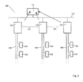
Figur 3 zeigt eine schematische Darstellung eines Datenaustausches gemäß einer anderen bevorzugten Ausführungsform des erfindungsgemäßen Verfahrens. - Nachfolgend wird im wesentlichen die vorteilhafte Verwendung des erfindungsgemäßen Verfahrens in Automatisierungssystemen, insbesondere Motion-Control-Systemen und Numerical-Control-Systemen, beschrieben, ohne dass das Verfahren auf diese Anwendung beschränkt ist.
- In
Figur 1 ist ein Verbund verschiedener Netzwerke insgesamt mit 100 bezeichnet. Es ist ein überlagertes nicht echtzeitfähiges Netzwerk 110 mit drei unterlagerten echtzeitfähigen Netzwerken 120, 130, 140 verbunden. Die drei echtzeitfähigen Netzwerke 120, 130, 140 weisen eine gemeinsame Zeitbasis auf, die über eine echtzeitfähige Kommunikationsverbindung 101, 101' synchronisiert wird. Das nicht echtzeitfähige Netzwerk 110 weist einen Teilnehmer 111, beispielsweise einen PC, auf. - Die echtzeitfähigen Netzwerke 120, 130, 140 sind als Steuerungssysteme ausgebildet. Sie weisen jeweils eine Steuerung oder SPS 121, 131, 141 auf, an die jeweils weitere Teilnehmer 122, 123; 132, 133; 142, 143, beispielsweise Sensoren oder Aktoren, über echtzeitfähige Verbindungen angeschlossen sind.
- Bei der Durchführung des Verfahrens ist nun die Triggerung der drei unterlagerten Systeme erwünscht, um Diagnosedaten abzufragen. Der PC 111 sendet das Triggersignal an die Steuerungen 121, 131, 141 über das nicht echtzeitfähige Netzwerk 110. Aufgrund der nicht echtzeitfähigen Verbindung ist die Laufzeit der Signale bis zum Erreichen der Steuerungen undeterminiert.
- Sobald ein Triggersignal eine Steuerung 121, 131, 141 erreicht, beginnt diese Steuerung 121, 131, 141 mit der Datenaufzeichnung. Da die Laufzeit der Triggersignale vom PC 111 zu den Steuerungen 121, 131, 141 unterschiedlich ist, ist auch der Startzeitpunkt der Datenaufzeichnung unterschiedlich.
- Die Steuerungen 121, 131, 141 versehen nun ihre Daten, beispielsweise zu Beginn der Messung, mit einem gültigen Zeitstempel 124, 134, 144. Da der zeitliche Ablauf einer Messung, im vorliegenden Beispiel eine Messung über zehn Zeiteinheiten, bekannt ist, kann der Zeitstempel 124, 134, 144 auch zu jedem anderen beliebigen Zeitpunkt, beispielsweise am Ende oder in der Mitte der Messung, hinzugefügt werden. Es versteht sich, dass ein Zeitstempel auch zu jeder Zeiteinheit zu den Daten hinzugefügt werden könnte.
- Die Laufzeiten zwischen den einzelnen Teilnehmern 121, 122, 123; 131, 132, 133; 141, 142, 143 innerhalb eines Netzwerks 120, 130, 140 sind determiniert und bekannt. Im vorliegenden Beispiel beträgt die Laufzeit zwischen den einzelnen Teilnehmern genau eine Zeiteinheit.
- In
Figur 2 ist das Ergebnis des inFigur 1 beschriebenen Verfahrens gezeigt. Es wurde eine Aufzeichnungsdauer von zehn Zeiteinheiten gewählt. Zum Zeitpunkt Null 250 werden die Triggersignale an die Steuerungen 121, 131, 141 gesendet. Daraufhin wird von den drei Steuerungen je ein Datensatz 221, 231, 241 über die Zeit t geliefert. Jeder Datensatz enthält wenigstens einen Zeitstempel. Aus diesem Zeitstempel ist der Startzeitpunkt und der Endzeitpunkt der Messung ersichtlich. - Der Datensatz 221 der ersten Steuerung 121 beginnt zum Zeitpunkt 0,15 Zeiteinheiten und endet zum Zeitpunkt 10,15 Zeiteinheiten. Der Datensatz 231 der zweiten Steuerung 131 beginnt zum Zeitpunkt 2,73 Zeiteinheiten und endet zum Zeitpunkt 12,73 Zeiteinheiten. Der Datensatz 241 der dritten Steuerung 141 beginnt zum Zeitpunkt 3,94 Zeiteinheiten und endet zum Zeitpunkt 13,94 Zeiteinheiten.
- Die determinierten Zeitstempel ermöglichen, eine zeitliche Beziehung zwischen den einzelnen Datensätzen herzustellen. Aus dem dargelegten Beispiel kann ein überlappendes Zeitintervall 260 zwischen den Zeitpunkten 3,94 Zeiteinheiten und 10,15 Zeiteinheiten ermittelt werden. Während dieses Zeitintervalls 260 wurden die Messungen in den verschiedenen unterlegten Netzwerken gleichzeitig durchgeführt. Dieses Zeitintervall 260 kann vorteilhafterweise zur Auswertung der Daten verwendet werden.
-
Figur 3 zeigt eine weitere bevorzugte Ausführungsform des erfindungsgemäßen Verfahrens. - Ein Verbund verschiedener Netzwerke ist insgesamt mit 100 bezeichnet. Es ist ein überlagertes nicht echtzeitfähiges Netzwerk 110 mit drei unterlagerten echtzeitfähigen Netzwerken 120, 130, 140 verbunden. Die drei echtzeitfähigen Netzwerke 120, 130, 140 weisen eine gemeinsame Zeitbasis auf, die über die echtzeitfähige Kommunikationsverbindung 101, 101' synchronisiert wird. Das nicht echtzeitfähige Netzwerk 110 weist einen Teilnehmer 111, beispielsweise einen PC, auf.
- Die echtzeitfähigen Netzwerke 120, 130, 140 sind als Steuerungssysteme ausgebildet. Sie weisen jeweils eine Steuerung oder SPS 121, 131, 141 auf, an die jeweils weitere Teilnehmer 122, 123; 132, 133; 142, 143, beispielsweise Sensoren oder Aktoren, über echtzeitfähige Verbindungen angeschlossen sind.
- Bei der Durchführung des Verfahrens ist nun das Feststellen einer vorbestimmten Verknüpfung mehrerer Triggerbedingungen aus verschiedenen Netzwerken erwünscht. Liegt eine Triggerbedingung in einem unterlagerten Netzwerk vor, wird sie an den PC 111 gemeldet. Der PC 111 kann nun bei Auftreten mehrerer Triggerereignisse in den verschiedenen Netzwerken 120, 130, 140 einen Zusammenhang herstellen und das Auftreten der vorbestimmten verknüpften Triggerbedingung feststellen.
- Wird das Feststellen des gleichzeitigen Auftretens der Triggerereignisse gewünscht oder benötigt, kann das Triggerereignis mit einem Zeitstempel versehen und an den PC 111 gemeldet werden.
Claims (11)
- Verfahren zum Austauschen von Daten zwischen Teilnehmern bzw. Knoten (111, 121, 122, 123, 131, 132, 133, 141, 142, 143) aus wenigstens zwei echtzeitfähigen, als Steuerungssysteme (120, 130, 140) ausgebildeten Netzwerken und wenigstens einem nicht echtzeitfähigen Netzwerk (110), wobei Daten, die in einem echtzeitfähigen Netzwerk (120, 130, 140) erzeugt werden, ein Zeitstempel hinzugefügt wird, wobei wenigstens zwei der echtzeitfähigen Netzwerke (120, 130, 140) zueinander zeitsynchron sind und eine gemeinsame Zeitbasis aufweisen, die über eine.echtzeitfähige Kommunikationsverbindung (101, 101') synchronisiert wird.
- Verfahren nach Anspruch 1,
dadurch gekennzeichnet, dass
mit einem Zeitstempel versehene Daten an einen Teilnehmer (111) eines nicht echtzeitfähigen Netzwerkes (110) übertragen werden. - Verfahren nach einem der vorstehenden Ansprüche,
dadurch gekennzeichnet, dass
mit einem Zeitstempel versehene Daten von verschiedenen Sendern (121, 122, 123, 131, 132, 133, 141, 142, 143), insbesondere aus verschiedenen Netzwerken (120, 130, 140), vom Empfänger (111, 121, 122, 123, 131, 132, 133, 141, 142, 143) in eine zeitliche Beziehung (260) zueinander gebracht werden. - Verfahren nach einem der vorstehenden Ansprüche,
dadurch gekennzeichnet, dass
alle echtzeitfähigen Netzwerke (120, 130, 140) zueinander zeitsynchron sind. - Verfahren nach einem der vorstehenden Ansprüche,
dadurch gekennzeichnet, dass
es in Automatisierungssystemen, insbesondere Motion-Control-Systemen und Numerical-Control-Systemen, verwendet wird. - Verfahren nach einem der vorstehenden Ansprüche,
dadurch gekennzeichnet, dass
Triggersignale verschiedener Teilnehmer (111, 121, 122, 123, 131, 132, 133, 141, 142, 143), insbesondere aus verschiedenen Netzwerken (110, 120, 130, 140), kombiniert bzw. verknüpft werden. - Verfahren nach Anspruch 6,
dadurch gekennzeichnet, dass
die Kombination der Triggersignale als neues Triggersignal an Teilnehmer (111, 121, 122, 123, 131, 132, 133, 141, 142, 143), insbesondere aus verschiedenen Netzwerken (110, 120, 130, 140), übertragen wird. - Vorrichtung zum Austauschen von Daten zwischen Teilnehmern bzw. Knoten (111, 121, 122, 123, 131, 132, 133, 141, 142, 143) aus echtzeitfähigen, als Steuerungssysteme (120, 130, 140) ausgebildeten Netwerken und nicht echtzeitfähigen Netzwerken (110) mit
Mitteln zur Hinzufügung von Zeitstempeln zu Daten, die in einem echtzeitfähigen Netzwerk (120, 130, 140) erzeugt werden,
Mitteln zur Bereitstellung einer Zeitsynchronität von echtzeitfähigen Netzwerken (120, 130, 140) durch Synchronisation einer gemeinsamen Zeitbasis über eine echtzeitfähige Kommunikationsverbindung (101, 101'). - Vorrichtung nach Anspruch 8 mit Mitteln zur Durchführung eines Verfahrens gemäß einem der Ansprüche 2 bis 7.
- Vorrichtung nach Anspruch 8 oder 9
gekennzeichnet durch
Mittel zur Kombination bzw. Verknüpfung von Triggersignalen verschiedener Teilnehmer (111, 121, 122, 123, 131, 132, 133, 141, 142, 143), insbesondere aus verschiedenen Netzwerken (110, 120, 130, 140). - Vorrichtung nach einem der Ansprüche 8 bis 10 zur Verwendung in Automatisierungssystemen, insbesondere Motion-Control-Systemen und Numerical-Control-Systemen.
Applications Claiming Priority (2)
| Application Number | Priority Date | Filing Date | Title |
|---|---|---|---|
| DE102004052555A DE102004052555A1 (de) | 2004-10-29 | 2004-10-29 | Verfahren zum Austauschen von Daten zwischen Teilnehmern aus verschiedenen Netzwerken |
| PCT/EP2005/011213 WO2006048118A1 (de) | 2004-10-29 | 2005-10-19 | Verfahren zum austauschen von daten zwischen teilnehmern aus verschiedenen netzwerken |
Publications (2)
| Publication Number | Publication Date |
|---|---|
| EP1810096A1 EP1810096A1 (de) | 2007-07-25 |
| EP1810096B1 true EP1810096B1 (de) | 2011-06-15 |
Family
ID=35448354
Family Applications (1)
| Application Number | Title | Priority Date | Filing Date |
|---|---|---|---|
| EP05797789A Expired - Lifetime EP1810096B1 (de) | 2004-10-29 | 2005-10-19 | Verfahren zum austauschen von daten zwischen teilnehmern aus verschiedenen netzwerken |
Country Status (6)
| Country | Link |
|---|---|
| US (1) | US7924888B2 (de) |
| EP (1) | EP1810096B1 (de) |
| JP (1) | JP2008518534A (de) |
| AT (1) | ATE513258T1 (de) |
| DE (1) | DE102004052555A1 (de) |
| WO (1) | WO2006048118A1 (de) |
Cited By (1)
| Publication number | Priority date | Publication date | Assignee | Title |
|---|---|---|---|---|
| DE102017108571A1 (de) | 2017-04-21 | 2018-10-25 | Beckhoff Automation Gmbh | Konzept zum übermitteln von zeitsynchronisierten daten von einer eine lokale zeit aufweisenden steuerung eines automatisierungssystems an zumindest einen teilnehmer des automatisierungssystems |
Families Citing this family (18)
| Publication number | Priority date | Publication date | Assignee | Title |
|---|---|---|---|---|
| DE102006039244A1 (de) | 2006-08-22 | 2008-03-06 | Robert Bosch Gmbh | Automatisierungssystem und Verfahren zur Taktzeit-, Prozess- und/oder Maschinenoptimierung |
| US7636759B1 (en) * | 2008-09-29 | 2009-12-22 | Gene Fein | Rotating encryption in data forwarding storage |
| US9203928B2 (en) | 2008-03-20 | 2015-12-01 | Callahan Cellular L.L.C. | Data storage and retrieval |
| US7599997B1 (en) * | 2008-08-01 | 2009-10-06 | Gene Fein | Multi-homed data forwarding storage |
| US8458285B2 (en) * | 2008-03-20 | 2013-06-04 | Post Dahl Co. Limited Liability Company | Redundant data forwarding storage |
| US7636761B1 (en) * | 2008-09-29 | 2009-12-22 | Gene Fein | Measurement in data forwarding storage |
| US8386585B2 (en) * | 2008-04-25 | 2013-02-26 | Tajitshu Transfer Limited Liability Company | Real-time communications over data forwarding framework |
| US8452844B2 (en) * | 2008-05-07 | 2013-05-28 | Tajitshu Transfer Limited Liability Company | Deletion in data file forwarding framework |
| US8370446B2 (en) * | 2008-07-10 | 2013-02-05 | Tajitshu Transfer Limited Liability Company | Advertisement forwarding storage and retrieval network |
| US8599678B2 (en) * | 2008-07-10 | 2013-12-03 | Tajitshu Transfer Limited Liability Company | Media delivery in data forwarding storage network |
| US8352635B2 (en) * | 2008-09-29 | 2013-01-08 | Tajitshu Transfer Limited Liability Company | Geolocation assisted data forwarding storage |
| US8478823B2 (en) * | 2008-09-29 | 2013-07-02 | Tajitshu Transfer Limited Liability Company | Selective data forwarding storage |
| EP2434357B1 (de) * | 2010-09-22 | 2020-02-12 | Siemens Aktiengesellschaft | Tracesystem für Technologiedaten und/oder Programmereignisse |
| EP2434360B1 (de) * | 2010-09-22 | 2020-01-08 | Siemens Aktiengesellschaft | Bewegungssteuerungssystem |
| DE102016117101A1 (de) * | 2016-09-12 | 2018-03-15 | Komet Group Gmbh | Verfahren zum Überwachen von zumindest einer Werkzeugmaschine und Fertigungsanlage |
| CN113515473B (zh) * | 2020-04-09 | 2024-06-14 | 珠海全志科技股份有限公司 | 一种QoS控制方法、总线系统、计算装置和存储介质 |
| DE102023203210A1 (de) | 2023-04-06 | 2024-10-10 | Robert Bosch Gesellschaft mit beschränkter Haftung | Verfahren zur Synchronisation von Netzwerken |
| JP2025006655A (ja) * | 2023-06-29 | 2025-01-17 | ファーザーシステム株式会社 | ネットワーク制御システムおよびプログラム |
Family Cites Families (12)
| Publication number | Priority date | Publication date | Assignee | Title |
|---|---|---|---|---|
| US5774377A (en) | 1991-07-30 | 1998-06-30 | Hewlett-Packard Company | Method and apparatus for monitoring a subsystem within a distributed system for providing an archive of events within a certain time of a trap condition |
| US6347084B1 (en) * | 1998-05-28 | 2002-02-12 | U.S. Philips Corporation | Method of timestamp synchronization of a reservation-based TDMA protocol |
| US6282192B1 (en) * | 2000-01-27 | 2001-08-28 | Cisco Technology, Inc. | PSTN fallback using dial on demand routing scheme |
| US6845416B1 (en) * | 2000-08-02 | 2005-01-18 | National Instruments Corporation | System and method for interfacing a CAN device and a peripheral device |
| US6760687B2 (en) * | 2001-05-31 | 2004-07-06 | Fisher-Rosemount Systems, Inc. | Sequence of events detection in a process control system |
| DE10202092A1 (de) * | 2002-01-21 | 2003-08-14 | Siemens Ag | Verfahren und Vorrichtung zum Erfassen und Verarbeiten von Signalen von industriellen Prozessen |
| US7451206B2 (en) * | 2002-05-20 | 2008-11-11 | Siemens Communications, Inc. | Send of software tracer messages via IP from several sources to be stored by a remote server |
| JP2004054555A (ja) * | 2002-07-19 | 2004-02-19 | Yokogawa Electric Corp | 表示装置 |
| US7372875B2 (en) * | 2002-09-30 | 2008-05-13 | Lucent Technologies Inc. | Systems and methods for synchronization in asynchronous transport networks |
| US7103426B2 (en) * | 2003-01-28 | 2006-09-05 | Rosemount Analytical Inc. | Anticipatory high frequency noise compensation in a distributed process control system |
| JP2004272403A (ja) * | 2003-03-06 | 2004-09-30 | Mitsubishi Electric Corp | プロセス入出力装置及びこれを用いた監視制御システム |
| US20050268019A1 (en) * | 2004-06-01 | 2005-12-01 | Che-Hui Chang Chien | [interface and system for transmitting real-time data ] |
-
2004
- 2004-10-29 DE DE102004052555A patent/DE102004052555A1/de not_active Ceased
-
2005
- 2005-10-19 WO PCT/EP2005/011213 patent/WO2006048118A1/de not_active Ceased
- 2005-10-19 EP EP05797789A patent/EP1810096B1/de not_active Expired - Lifetime
- 2005-10-19 US US11/573,007 patent/US7924888B2/en not_active Expired - Fee Related
- 2005-10-19 AT AT05797789T patent/ATE513258T1/de active
- 2005-10-19 JP JP2007538305A patent/JP2008518534A/ja active Pending
Cited By (2)
| Publication number | Priority date | Publication date | Assignee | Title |
|---|---|---|---|---|
| DE102017108571A1 (de) | 2017-04-21 | 2018-10-25 | Beckhoff Automation Gmbh | Konzept zum übermitteln von zeitsynchronisierten daten von einer eine lokale zeit aufweisenden steuerung eines automatisierungssystems an zumindest einen teilnehmer des automatisierungssystems |
| US10873519B2 (en) | 2017-04-21 | 2020-12-22 | Beckhoff Automation Gmbh | System and method for transmitting time-synchronized data from a controller of an automation system comprising a local time to at least one subscriber of the automation system |
Also Published As
| Publication number | Publication date |
|---|---|
| EP1810096A1 (de) | 2007-07-25 |
| DE102004052555A1 (de) | 2006-05-04 |
| JP2008518534A (ja) | 2008-05-29 |
| WO2006048118A1 (de) | 2006-05-11 |
| ATE513258T1 (de) | 2011-07-15 |
| US7924888B2 (en) | 2011-04-12 |
| US20090028191A1 (en) | 2009-01-29 |
Similar Documents
| Publication | Publication Date | Title |
|---|---|---|
| EP1810096B1 (de) | Verfahren zum austauschen von daten zwischen teilnehmern aus verschiedenen netzwerken | |
| EP2637361B1 (de) | Verfahren zur Bestimmung der Topologie eines seriellen asynchronen Datenbusses | |
| EP1919132B1 (de) | Diagnoseverfahren und -vorrichtung für ein Feldbussystem | |
| WO2002076033A2 (de) | Synchrones, getaktetes kommunikationssystem mit dezentralen ein-/ausgabe-baugruppen und verfahren zur einbindung dezentraler ein-/ausgabe-baugruppen in ein solches system | |
| DE3431171A1 (de) | Gleisfreimeldeeinrichtung mit achszaehlung | |
| EP3022856B1 (de) | Verfahren zur lokalisierung einer frequenzabweichung in einem kommunikationsnetz und entsprechendes kommunikationsnetz | |
| EP3996298A1 (de) | Zeitsynchronisation in einem echtzeit-netzwerk | |
| DE2741214B2 (de) | Schaltungsanordnung für eine zyklisch arbeitende elektronische Empfangs-, Verkehrsmeß-, Auswerte- und Registriereinrichtung in Fernmelde-, insbesondere Fernsprechvermittlungsanlagen | |
| DE102004050386B4 (de) | Verfahren zur Analyse eines technischen Prozesses | |
| EP3208674A1 (de) | Netzwerksystem und verfahren zur datenübertragung in einem netzwerksystem | |
| DE60034236T2 (de) | System und Verfahren zur Synchronisation von Netzelementen | |
| EP1484679A2 (de) | Sicherstellung von maximalen Reaktionszeiten in komplexen oder verteilten sicheren und/oder nicht sicheren Systemen | |
| EP2287693B1 (de) | Verfahren zum synchronen Erfassen und Aufzeichnen von Prozess- und/oder Zustandsdaten sowie Automatisierungssystem | |
| DE102004012506B4 (de) | Verfahren zur Erfassung von Signalen in einer zentralen Erfassungseinheit | |
| DE3609430C2 (de) | ||
| EP1408386B1 (de) | Verfahren und Vorrichtung zur Datenübertragung zwischen einer Verarbeitungseinheit und mehreren Positionsmesseinrichtungen | |
| DE102007020440B4 (de) | Synchronisationsbussystem, Kommunikationseinheiten für ein Synchronisationsbussystem und Verfahren zum Austauschen von Nachrichten zur zeitlichen Synchronisation | |
| WO2008046124A2 (de) | Verfahren und einrichtung zum überprüfen eines bussystems | |
| DE10048747B4 (de) | Verfahren und Verarbeiten von Prozesssignalen | |
| DE102023203210A1 (de) | Verfahren zur Synchronisation von Netzwerken | |
| WO2012019617A1 (de) | Verfahren und vorrichtung zum synchronisieren von ereignissen autarker systeme | |
| DE102006008634A1 (de) | Mikrocontrollersystem mit Peripherieeinheiten | |
| DE102006010748A1 (de) | Verfahren zum Aufzeichnen von Eingangssignaländerungen | |
| DE102006040986B4 (de) | Verfahren zum Testen des Verhaltens von Busteilnehmern in einem Flexray-Bussystem | |
| EP0629965B1 (de) | Verfahren zur Erfassung von Daten aus elektronischen Steuergeräten |
Legal Events
| Date | Code | Title | Description |
|---|---|---|---|
| PUAI | Public reference made under article 153(3) epc to a published international application that has entered the european phase |
Free format text: ORIGINAL CODE: 0009012 |
|
| 17P | Request for examination filed |
Effective date: 20070529 |
|
| AK | Designated contracting states |
Kind code of ref document: A1 Designated state(s): AT BE BG CH CY CZ DE DK EE ES FI FR GB GR HU IE IS IT LI LT LU LV MC NL PL PT RO SE SI SK TR |
|
| DAX | Request for extension of the european patent (deleted) | ||
| 17Q | First examination report despatched |
Effective date: 20081112 |
|
| GRAP | Despatch of communication of intention to grant a patent |
Free format text: ORIGINAL CODE: EPIDOSNIGR1 |
|
| GRAS | Grant fee paid |
Free format text: ORIGINAL CODE: EPIDOSNIGR3 |
|
| GRAA | (expected) grant |
Free format text: ORIGINAL CODE: 0009210 |
|
| AK | Designated contracting states |
Kind code of ref document: B1 Designated state(s): AT BE BG CH CY CZ DE DK EE ES FI FR GB GR HU IE IS IT LI LT LU LV MC NL PL PT RO SE SI SK TR |
|
| REG | Reference to a national code |
Ref country code: GB Ref legal event code: FG4D Free format text: NOT ENGLISH Ref country code: CH Ref legal event code: EP |
|
| REG | Reference to a national code |
Ref country code: IE Ref legal event code: FG4D Free format text: LANGUAGE OF EP DOCUMENT: GERMAN |
|
| REG | Reference to a national code |
Ref country code: DE Ref legal event code: R096 Ref document number: 502005011512 Country of ref document: DE Effective date: 20110721 |
|
| REG | Reference to a national code |
Ref country code: NL Ref legal event code: VDEP Effective date: 20110615 |
|
| PG25 | Lapsed in a contracting state [announced via postgrant information from national office to epo] |
Ref country code: LT Free format text: LAPSE BECAUSE OF FAILURE TO SUBMIT A TRANSLATION OF THE DESCRIPTION OR TO PAY THE FEE WITHIN THE PRESCRIBED TIME-LIMIT Effective date: 20110615 Ref country code: SE Free format text: LAPSE BECAUSE OF FAILURE TO SUBMIT A TRANSLATION OF THE DESCRIPTION OR TO PAY THE FEE WITHIN THE PRESCRIBED TIME-LIMIT Effective date: 20110615 |
|
| PG25 | Lapsed in a contracting state [announced via postgrant information from national office to epo] |
Ref country code: LV Free format text: LAPSE BECAUSE OF FAILURE TO SUBMIT A TRANSLATION OF THE DESCRIPTION OR TO PAY THE FEE WITHIN THE PRESCRIBED TIME-LIMIT Effective date: 20110615 Ref country code: SI Free format text: LAPSE BECAUSE OF FAILURE TO SUBMIT A TRANSLATION OF THE DESCRIPTION OR TO PAY THE FEE WITHIN THE PRESCRIBED TIME-LIMIT Effective date: 20110615 Ref country code: GR Free format text: LAPSE BECAUSE OF FAILURE TO SUBMIT A TRANSLATION OF THE DESCRIPTION OR TO PAY THE FEE WITHIN THE PRESCRIBED TIME-LIMIT Effective date: 20110916 Ref country code: FI Free format text: LAPSE BECAUSE OF FAILURE TO SUBMIT A TRANSLATION OF THE DESCRIPTION OR TO PAY THE FEE WITHIN THE PRESCRIBED TIME-LIMIT Effective date: 20110615 Ref country code: CY Free format text: LAPSE BECAUSE OF FAILURE TO SUBMIT A TRANSLATION OF THE DESCRIPTION OR TO PAY THE FEE WITHIN THE PRESCRIBED TIME-LIMIT Effective date: 20110615 |
|
| PG25 | Lapsed in a contracting state [announced via postgrant information from national office to epo] |
Ref country code: NL Free format text: LAPSE BECAUSE OF FAILURE TO SUBMIT A TRANSLATION OF THE DESCRIPTION OR TO PAY THE FEE WITHIN THE PRESCRIBED TIME-LIMIT Effective date: 20110615 |
|
| REG | Reference to a national code |
Ref country code: IE Ref legal event code: FD4D |
|
| PG25 | Lapsed in a contracting state [announced via postgrant information from national office to epo] |
Ref country code: IE Free format text: LAPSE BECAUSE OF FAILURE TO SUBMIT A TRANSLATION OF THE DESCRIPTION OR TO PAY THE FEE WITHIN THE PRESCRIBED TIME-LIMIT Effective date: 20110615 Ref country code: EE Free format text: LAPSE BECAUSE OF FAILURE TO SUBMIT A TRANSLATION OF THE DESCRIPTION OR TO PAY THE FEE WITHIN THE PRESCRIBED TIME-LIMIT Effective date: 20110615 Ref country code: IS Free format text: LAPSE BECAUSE OF FAILURE TO SUBMIT A TRANSLATION OF THE DESCRIPTION OR TO PAY THE FEE WITHIN THE PRESCRIBED TIME-LIMIT Effective date: 20111015 Ref country code: CZ Free format text: LAPSE BECAUSE OF FAILURE TO SUBMIT A TRANSLATION OF THE DESCRIPTION OR TO PAY THE FEE WITHIN THE PRESCRIBED TIME-LIMIT Effective date: 20110615 |
|
| PG25 | Lapsed in a contracting state [announced via postgrant information from national office to epo] |
Ref country code: RO Free format text: LAPSE BECAUSE OF FAILURE TO SUBMIT A TRANSLATION OF THE DESCRIPTION OR TO PAY THE FEE WITHIN THE PRESCRIBED TIME-LIMIT Effective date: 20110615 Ref country code: SK Free format text: LAPSE BECAUSE OF FAILURE TO SUBMIT A TRANSLATION OF THE DESCRIPTION OR TO PAY THE FEE WITHIN THE PRESCRIBED TIME-LIMIT Effective date: 20110615 Ref country code: PL Free format text: LAPSE BECAUSE OF FAILURE TO SUBMIT A TRANSLATION OF THE DESCRIPTION OR TO PAY THE FEE WITHIN THE PRESCRIBED TIME-LIMIT Effective date: 20110615 |
|
| PLBE | No opposition filed within time limit |
Free format text: ORIGINAL CODE: 0009261 |
|
| STAA | Information on the status of an ep patent application or granted ep patent |
Free format text: STATUS: NO OPPOSITION FILED WITHIN TIME LIMIT |
|
| BERE | Be: lapsed |
Owner name: BOSCH REXROTH A.G. Effective date: 20111031 |
|
| 26N | No opposition filed |
Effective date: 20120316 |
|
| PG25 | Lapsed in a contracting state [announced via postgrant information from national office to epo] |
Ref country code: IT Free format text: LAPSE BECAUSE OF FAILURE TO SUBMIT A TRANSLATION OF THE DESCRIPTION OR TO PAY THE FEE WITHIN THE PRESCRIBED TIME-LIMIT Effective date: 20110615 Ref country code: MC Free format text: LAPSE BECAUSE OF NON-PAYMENT OF DUE FEES Effective date: 20111031 |
|
| REG | Reference to a national code |
Ref country code: CH Ref legal event code: PL |
|
| GBPC | Gb: european patent ceased through non-payment of renewal fee |
Effective date: 20111019 |
|
| PG25 | Lapsed in a contracting state [announced via postgrant information from national office to epo] |
Ref country code: DK Free format text: LAPSE BECAUSE OF FAILURE TO SUBMIT A TRANSLATION OF THE DESCRIPTION OR TO PAY THE FEE WITHIN THE PRESCRIBED TIME-LIMIT Effective date: 20110615 |
|
| REG | Reference to a national code |
Ref country code: DE Ref legal event code: R097 Ref document number: 502005011512 Country of ref document: DE Effective date: 20120316 |
|
| REG | Reference to a national code |
Ref country code: FR Ref legal event code: ST Effective date: 20120629 |
|
| PG25 | Lapsed in a contracting state [announced via postgrant information from national office to epo] |
Ref country code: BE Free format text: LAPSE BECAUSE OF NON-PAYMENT OF DUE FEES Effective date: 20111031 Ref country code: LI Free format text: LAPSE BECAUSE OF NON-PAYMENT OF DUE FEES Effective date: 20111031 Ref country code: CH Free format text: LAPSE BECAUSE OF NON-PAYMENT OF DUE FEES Effective date: 20111031 |
|
| PG25 | Lapsed in a contracting state [announced via postgrant information from national office to epo] |
Ref country code: FR Free format text: LAPSE BECAUSE OF NON-PAYMENT OF DUE FEES Effective date: 20111102 Ref country code: GB Free format text: LAPSE BECAUSE OF NON-PAYMENT OF DUE FEES Effective date: 20111019 |
|
| PG25 | Lapsed in a contracting state [announced via postgrant information from national office to epo] |
Ref country code: ES Free format text: LAPSE BECAUSE OF FAILURE TO SUBMIT A TRANSLATION OF THE DESCRIPTION OR TO PAY THE FEE WITHIN THE PRESCRIBED TIME-LIMIT Effective date: 20110926 |
|
| PG25 | Lapsed in a contracting state [announced via postgrant information from national office to epo] |
Ref country code: LU Free format text: LAPSE BECAUSE OF NON-PAYMENT OF DUE FEES Effective date: 20111019 |
|
| PG25 | Lapsed in a contracting state [announced via postgrant information from national office to epo] |
Ref country code: BG Free format text: LAPSE BECAUSE OF FAILURE TO SUBMIT A TRANSLATION OF THE DESCRIPTION OR TO PAY THE FEE WITHIN THE PRESCRIBED TIME-LIMIT Effective date: 20110915 |
|
| PG25 | Lapsed in a contracting state [announced via postgrant information from national office to epo] |
Ref country code: TR Free format text: LAPSE BECAUSE OF FAILURE TO SUBMIT A TRANSLATION OF THE DESCRIPTION OR TO PAY THE FEE WITHIN THE PRESCRIBED TIME-LIMIT Effective date: 20110615 |
|
| PG25 | Lapsed in a contracting state [announced via postgrant information from national office to epo] |
Ref country code: HU Free format text: LAPSE BECAUSE OF FAILURE TO SUBMIT A TRANSLATION OF THE DESCRIPTION OR TO PAY THE FEE WITHIN THE PRESCRIBED TIME-LIMIT Effective date: 20110615 |
|
| PG25 | Lapsed in a contracting state [announced via postgrant information from national office to epo] |
Ref country code: PT Free format text: LAPSE BECAUSE OF FAILURE TO SUBMIT A TRANSLATION OF THE DESCRIPTION OR TO PAY THE FEE WITHIN THE PRESCRIBED TIME-LIMIT Effective date: 20110615 |
|
| PGFP | Annual fee paid to national office [announced via postgrant information from national office to epo] |
Ref country code: PL Payment date: 20181123 Year of fee payment: 11 |
|
| REG | Reference to a national code |
Ref country code: AT Ref legal event code: MM01 Ref document number: 513258 Country of ref document: AT Kind code of ref document: T Effective date: 20191019 |
|
| PG25 | Lapsed in a contracting state [announced via postgrant information from national office to epo] |
Ref country code: AT Free format text: LAPSE BECAUSE OF NON-PAYMENT OF DUE FEES Effective date: 20191019 |
|
| PGFP | Annual fee paid to national office [announced via postgrant information from national office to epo] |
Ref country code: DE Payment date: 20221215 Year of fee payment: 18 |
|
| REG | Reference to a national code |
Ref country code: DE Ref legal event code: R119 Ref document number: 502005011512 Country of ref document: DE |
|
| PG25 | Lapsed in a contracting state [announced via postgrant information from national office to epo] |
Ref country code: DE Free format text: LAPSE BECAUSE OF NON-PAYMENT OF DUE FEES Effective date: 20240501 |