EP1810534B1 - Kommunikation zwischen einem funkgeräte -steuerknoten und mehreren abgesetzten funkgeräte-knoten - Google Patents
Kommunikation zwischen einem funkgeräte -steuerknoten und mehreren abgesetzten funkgeräte-knoten Download PDFInfo
- Publication number
- EP1810534B1 EP1810534B1 EP05795927.2A EP05795927A EP1810534B1 EP 1810534 B1 EP1810534 B1 EP 1810534B1 EP 05795927 A EP05795927 A EP 05795927A EP 1810534 B1 EP1810534 B1 EP 1810534B1
- Authority
- EP
- European Patent Office
- Prior art keywords
- node
- rec
- transmission
- link
- data
- Prior art date
- Legal status (The legal status is an assumption and is not a legal conclusion. Google has not performed a legal analysis and makes no representation as to the accuracy of the status listed.)
- Expired - Lifetime
Links
Images






Classifications
-
- H—ELECTRICITY
- H04—ELECTRIC COMMUNICATION TECHNIQUE
- H04W—WIRELESS COMMUNICATION NETWORKS
- H04W88/00—Devices specially adapted for wireless communication networks, e.g. terminals, base stations or access point devices
- H04W88/08—Access point devices
- H04W88/085—Access point devices with remote components
-
- H—ELECTRICITY
- H04—ELECTRIC COMMUNICATION TECHNIQUE
- H04J—MULTIPLEX COMMUNICATION
- H04J3/00—Time-division multiplex systems
- H04J3/02—Details
- H04J3/06—Synchronising arrangements
- H04J3/0635—Clock or time synchronisation in a network
- H04J3/0682—Clock or time synchronisation in a network by delay compensation, e.g. by compensation of propagation delay or variations thereof, by ranging
-
- H—ELECTRICITY
- H04—ELECTRIC COMMUNICATION TECHNIQUE
- H04J—MULTIPLEX COMMUNICATION
- H04J3/00—Time-division multiplex systems
- H04J3/02—Details
- H04J3/06—Synchronising arrangements
- H04J3/0635—Clock or time synchronisation in a network
- H04J3/0685—Clock or time synchronisation in a node; Intranode synchronisation
- H04J3/0691—Synchronisation in a TDM node
Definitions
- the present invention is directed to distributed radio base stations where a base station includes a main baseband processing unit coupled to one or more remote radio units where RF processing occurs, and in particular, to the radio interface between the main baseband processing unit and the one or more remote radio units.
- wireless user equipment units communicate via a radio access network (RAN) with one or more core networks.
- the user equipment units can be mobile stations such as mobile telephones ("cellular" telephones) and laptops with mobile termination, and thus can be, for example, portable, pocket, hand-held, computer-included, or car-mounted mobile devices which communicate voice and/or data with radio access network.
- the wireless user equipment units can be fixed wireless devices, e.g., fixed cellular devices/terminals which are part of a wireless local loop or the like.
- the radio access network covers a geographical area which is divided into cell areas, with each cell area being served by a radio base station.
- a cell is a geographical area where radio coverage is provided by the radio equipment at a base station site. Each cell is identified by a unique identity, which is broadcast in the cell.
- the radio base stations communicate over the air interface with the user equipment units (UE) within range of the base stations.
- UE user equipment units
- BSC base station controller
- RNC radio network controller
- EP 0993207 A2 discloses a serial BSC coupled to multiple series-connected base stations.
- the control node supervises and coordinates various activities of connected plural radio base stations.
- the control node is typically connected to one or more core networks.
- a conventional radio base station in a cellular communications system is generally located in a single location, and the distance between the baseband circuitry and the radio circuitry is relatively short, e.g., on the order of one meter.
- a distributed radio base station includes the radio equipment control (REC) and the radio equipment (RE).
- REC radio equipment control
- RE radio equipment
- WO 95/05722 includes an example distributed radio base station. Both parts may be physically separated, (i.e., the RE may be close to the antenna, whereas the REC is located in a conveniently accessible site), or both may be co-located as in a conventional radio base station design.
- the radio equipment control (REC) performs baseband signal processing, and each radio equipment (RE) converts between baseband and radio frequencies and transmits and receives signals over one or more antennas.
- Each RE serves a certain geographic area, sector, or cell.
- Separate, dedicated optical and/or electrical links connect the radio equipment control (REC) to each of the plural remote radio equipment (RE).
- the term link as used hereafter refers to a logical link and is not limited to any particular physical medium.
- Each link carries digital information downlink from the REC to the RE and digital information uplink from the RE to the REC.
- Document CPRI Specification v1.0 (30-09-2003 ) discloses the Common Public Radio Interface. This interface is an internal interface to radio base stations between Radio Equipments and Radio Equipment Controllers.
- a standardized common interface between a REC and one or more REs Such a standardized interface enables flexible and efficient product differentiation for radio base stations and independent technology evolution for the RE and REC.
- a standard would preferably define necessary items for transport, connectivity, and control including user plane data, control and management (C&M) plane transport mechanisms, and synchronization.
- Standardization would be particularly beneficial for hardware-dependent layers, e.g., physical layers, to ensure technology evolution on both sides of the interface with only a limited need for hardware adaptation.
- One advantageous result is that product differentiation in terms of functionality, management, and characteristics is not limited.
- an interface, apparatus, and method for communication between a radio equipment control (REC) node and a-radio equipment (RE) nodes in a distributed radio base station that transceives information over the radio interface using multiple antenna-carriers.
- the REC node is separate from and coupled to a first RE node by a first transmission link
- the first RE node is separate from and coupled to a second RE node by a second transmission link.
- Both control information and user information are generated for transmission over the first transmission link from one of the REC node and the RE node to the other, and over the second transmission link between the first RE node and the second RE node.
- the user information includes multiple data flows. Each data flow corresponds to data associated with one antenna per one radio carrier.
- the control and user information are formatted into multiple time division multiplexed (TDM) frames.
- TDM time division multiplexed
- Each basic TDM frame includes a control time slot for the control information and multiple data time slots for the user information.
- Each data time slot corresponds to a data flow of one of the antenna carriers.
- the frames are then transmitted over the transmission link to the other node.
- the time period of the frame corresponds to one CDMA chip time period.
- Each antenna carrier has a corresponding time slot in the frame so that the data samples for each antenna carrier are inserted in the antenna carrier's corresponding time slot.
- the corresponding time slot position in the frame may be fixed or it may be variable.
- the control information includes multiple different control flows, and a portion of them is included in the control time slot.
- the different control flows may include, for example, four control flows: radio interface and timing synchronization information, control and management (C&M) information, layer 1 (L1) control information, and extension information.
- the control and management information includes both fast and slow control and management information, and the L1 signaling indicates the bit rate of both.
- the control time slots may be arranged into 64 subchannels. Each such subchannel corresponds to every 64 th control time slot. The 64 subchannels may then be allocated to carry the four control flows. Multiple basic frames may be combined into a hyperframe, and multiple hyperframes may be combined into a radio frame. One or more borders of the hyperframe are used to map each control time slot to a respective assigned subchannel. Each of the four control words within a hyperframe carries one subflow of a control flow.
- the control information includes a known symbol for use in obtaining synchronization between the REC and the RE.
- the synchronization includes detecting the known symbol to retrieve one or more hyperframe borders.
- the known signal is periodically provided, and synchronization is obtained without requiring a feedback signal be sent in response to detecting the known signal.
- the known signal is a K28.5 symbol.
- Start-up communication between the REC and the RE include negotiations of one or more characteristics for the transmission link.
- the negotiations begin with the REC sending transmissions over the interface, with each transmission using one of several different line bit rates.
- the RE attempts to detect the line bit rate of each such transmission. If the RE detects one of the REC transmissions, then the RE replies to the REC using the same line bit rate.
- one or both of the REC and RE transmit a highest, supported bit rate for one or more control and management flows.
- the node with the highest control and management bit rate adopts the highest rate supported by the other node.
- the REC proposes a lower C&M bit rate.
- a similar back-and-forth negotiation occurs with respect to the highest supported version of the REC-RE interface communications protocol.
- Another feature includes calibrating or compensating for a transmission time delay associated with the transmission link/internal interface. More specifically, the RE obtains an RE time difference between when a frame structure is received from the REC and when the frame structure is transmitted to the REC. Similarly, the REC determines an REC time difference between when a frame structure is received from the RE and when the frame structure is transmitted to the RE. A round-trip delay is determined by subtracting the RE time difference and the REC time difference.
- each link connects two node ports which have asymmetrical functions and roles: a master and a slave.
- the ports of the REC are master ports.
- An RE has at least one slave port and optionally one or more master ports depending on whether it is coupled to another RE.
- Multi-hop configurations present additional challenges as compared to single hop configurations, particularly in the area of synchronization.
- the handling of certain system-wide information is also important. Should certain information be passed onto the next RE node and should information not be passed onto the next RE node? Multiple advantages features are described to facilitate multi-hop base station configurations.
- a multi-hop configured radio base station exchanges data between a radio equipment control (REC) node and first and second radio equipment (RE) nodes for transceiving information over a radio interface using multiple antenna carriers.
- the REC node is separate from and coupled to the first RE node by a first transmission link.
- the first RE node is separate from and coupled to the second RE node by a second transmission link.
- Control information and user information are provided for transmission over the first transmission link from the REC node to the first RE node, and that information intended for the second RE is forwarded over the second transmission link from the first RE node to the second RE node.
- the control information includes layer 1 (L1) signaling, and the L1 signaling includes a service access point defect indicator (SDI) that indicates whether higher layers are operational for data, synchronization, or control and management (C&M).
- SDI service access point defect indicator
- C&M control and management
- the first RE #1 ignores the data received over the first transmission link, and forwards the SDI over the second transmission link to the second RE #2.
- the first RE node can transmit data received on a redundant first transmission link over the second transmission link to RE #2.
- the control information sent by the REC includes a reset indicator
- the first RE #1 initiates a reset operation for the first RE #1 and also sends the reset indicator to the second RE #2.
- Time delay calibration for multi-hop configuration is more complicated than for single hop.
- a first transmission time delay associated with the first transmission link and a second transmission time delay associated with the second transmission link are determined.
- the first and second transmission delays are used to determine in a loop delay associated with the REC node, the first RE #1, and the second RE #2.
- An example more detailed time delay compensation scheme for multi-hop includes each RE providing the REC with a time offset between the RE's input slave port and output slave port.
- the REC transmits a first frame synchronization signal to the first RE at a first time.
- the first RE provides the REC with a downlink delay associated with receiving a first frame synchronization signal on its input slave port and transmits the first frame synchronization signal on its output master port.
- the first RE provides the REC with an uplink delay associated with receiving a second frame synchronization signal on its input master port and transmits a third frame synchronization signal on its output slave port.
- the REC receives the third frame synchronization signal at a second time and determines a time difference between the first and second times.
- the REC determines a first transmission time delay associated with the first transmission link and a second transmission time delay associated with the second transmission link based on the time difference, the downlink delay, the uplink delay, and each time offset.
- UMTS universal mobile telecommunication systems
- WCDMA Wideband code division multiple access
- UMTS systems include logical network elements that each have a defined functionality.
- Figure 1 shows an example UMTS system.
- Network elements are grouped into the radio access network (RAN), sometimes as referred to as the UMTS Terrestrial RAN (UTRAN), that handles all radio-related functionality, and the core network (CN) which is responsible for switching and routing calls and data connections to external networks such as PSTN, ISDN, PLMN, and the Internet.
- the UTRAN covers a graphical area which is divided into cell areas, each cell area being served by a radio base station. A cell is a geographical area where radio coverage is provided by the radio equipment.
- the user equipment (UE) interfaces the user and the radio/air interface.
- the following description focuses on the node B which converts the data flow between the Iub interface and the radio/air interface Uu.
- the internal interface within the radio base station which links the REC to one or more REs is referred to herein as the common public radio interface (CPRI) as shown in Figure 3 .
- CPRI common public radio interface
- the CPRI interface could be used as a private interface.
- the following description is based on UMTS nomenclature, but is not limited just to UMTS systems, but instead, may be employed in any distributed radio base station.
- Figure 2A shows a point-to-point CPRI link between one REC and one RE.
- Figure 2B illustrates multiple, point-to-point CPRI links between one REC and RE
- Figure 2C illustrates multiple, point-to-point CPRI links between one REC and several REs (sometimes referred to as a "star" topology).
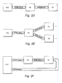
- Figure 2D shows a chain or cascade network topology with an intervening "networking" RE coupling the REC and the end RE.
- Figure 2E shows a tree network topology
- Figure 2F shows a ring network topology.
- Other topologies could be used, e.g., a combination of a ring and a tree topology.
- the radio equipment control (REC) node provides access to the Radio Network Controller via the Iub interface in a UMTS radio access network, whereas each radio equipment (RE) node serves as the air interface to the user equipment (in the UMTS network the air interface is called the Uu interface).
- the REC performs the radio functions of the digital baseband domain, whereas each RE performs the analog radio frequency (RF) functions.
- the functional split allows a generic CPRI interface based on In-phase and Quadrature (IQ) complex data can be defined.
- the REC is concerned with the Iub transports, the radio base station control and management, and the digital baseband processing.
- Each RE provides the analog and radio frequency functions such as filtering, modulation, frequency conversion, and amplification.
- Table 1 Functions of REC Functions of RE Downlink Uplink Downlink Uplink Radio base station control & management Iub transport RRC Channel Filtering Iub Frame protocols D/A conversion A/D conversion Channel Coding Channel De-coding Up Conversion Down Conversion Interleaving De-Interleaving ON/OFF control to each carrier Automatic Gain Control Spreading De-spreading Carrier Multiplexing Carrier Demultiplexing Scrambling De-scrambling Power amplification and limiting Low Noise Amplification Adding of physical channels Signal distribution to signal processing units Antenna supervision Transmit Power Control of each physical channel Transmit Power Control & Feedback Information detection RF filtering RF filtering Frame and slot signal generation (including clock stabilization) Measurements Measurements Measurements
- control and management (C&M) control signals as well as synchronization control signals are exchanged between the REC and each RE.
- All information streams or "planes”, including both control and user data, are multiplexed onto a digital serial communication line using layer 1 and layer 2 protocols. See Figure 3 .
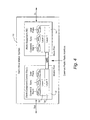
- the different information flows have access to the layer 2 via appropriate service access points (SAPs), as shown in Figure 4 .
- SAPs service access points
- the protocols for the physical layer (layer 1), and the data link layer (layer 2) are defined by the CPRI.
- Layer 1 defines electrical characteristics, optical characteristics, time division multiplexing of different data flows, and low level signaling.
- Layer 2 defines media access control, flow control, and data protection of the control and management information flow.
- a control plane includes control information used for call processing.
- a synchronization plane transfers synchronization and timing information between the REC and each RE.
- a management plane includes management information for the operation, administration, and maintenance of the CPRI interface and each RE.
- the user plane includes user data that must be transferred from the radio network station to the user equipment and vice versa.
- the user data are transferred in the form of complex data, referred to herein as IQ data, where "I" corresponds to the real or In-phase component of the complex signal and "Q" corresponds to the imaginary or Quadrature component of the complex signal.
- IQ data Several IQ data flows may be sent via one physical CPRI link, and each IQ data flow reflects the data of one antenna for one carrier, which is referred to as an antenna-carrier (AxC).
- AxC antenna-carrier
- One AxC is associated with the amount of digital user data for either reception or transmission of one carrier, e.g., a UTRA-FDD carrier at one independent antenna element. Stated differently, the AxC is the data to be transmitted on a specific frequency on a specific antenna.
- each AxC contains the information for multiple UEs superimposed on each other.
- the AxC "container" or time slot contains the user data (e.g., IQ samples) of the one AxC for one UMTS chip duration.
- Layer 2 service access points are defined for the information planes or data flows and are used as reference points for performance measurements. These service access points shown in Figure 4 are denoted as SAP CM , SAP S , and SAP IQ .
- the single hop configuration in Figure 4 shows a single link between the REC and the RE. The downlink direction is from the REC to the RE, and the uplink direction is from the RE to the REC.
- the REC includes a master port, and the RE includes a slave port.
- a networked topology includes at least one intervening RE node.
- Figure 5 shows examples of several defined terms useful in describing features or aspects of a networked topology, where the simplest networked topology includes an REC coupled to at least two REs with at least one of the REs being connected between the REC and the other RE.
- Figure 5 shows such a simple networked topology with RE#1 being the networking RE.
- master port and slave port are introduced.
- the sending port is a master port
- the receiving port is a slave port.
- the ports of the REC are always master ports..
- a RE has at least one slave port and has optionally other ports which can be slave or master.
- Figure 5 illustrates several master and slave port examples.
- link is used to indicate the bidirectional interface in between two directly connected ports, either between REC and RE, or between two REs, using one transmission line per direction.
- a working link consists of a master port, a bidirectional cable, and a slave port. Under normal conditions, a link has one master port and one slave port. For a link, the downlink direction is from a master to slave port, and the uplink direction is generally from a slave to master port.
- An active link supports "logical connections" (defined below) for synchronization, C&M data, and IQ data.
- a passive link does not support any C&M channel, i.e. it carries only IQ data and synchronization information, and may be used for capacity expansion or redundancy purposes.
- a “hop” is the aggregation of all links directly connecting two nodes.
- a hop is defined either between REC and RE, or between two REs.
- a “multi-hop connection” is composed of a set of continuously connected hops starting from the REC and ending at a particular RE including cables and networking REs in between. An example is illustrated in Figure 5 .
- Figure 5 also shows that an REC may have multiple master ports and that an RE may have multiple slave and/or master ports.
- the RE includes an address table managed by its application layer that decides to which master port to route information received on a slave port to send that information on to the next node. Multiple ports may be used to support redundant links that can be used if a primary link is detected as faulty.
- a "logical connection” defines the interconnection between a particular SAP (e.g., SAP CM ) belonging to a port of the REC and the corresponding peer SAP (e.g., SAP CM ) belonging to a port of one particular RE and builds upon a single hop or a multi-hop connection between the REC and that particular RE.
- Logical connections for C&M data (CM), user plane data (IQ), and synchronization (S) can be distinguished as is illustrated.
- Logical connections can be routed based on address routing tables in the
- Figure 6 is similar to Figure 4 and shows the system architecture for a simple "chain" networked topology.
- the intervening RE node has a set of SAPs for information transceived over its radio Uu interface and another set of SAPs for handling communicated with the second RE#2.
- the rates over the transmission links between REC and RE#1 and between RE#1 and RE#2 can vary depending on the application.
- a rate of transmission over the first transmission link is approximately otherwise on the order of 614.3 Mbit/s, 1228.8 Mbit/s, or 2457.6 Mbit/s.
- a rate of transmission over the first transmission link between REC and RE#1 may be the same as or different from the rate over the second transmission link between RE#1 and RE#2.
- a rate of transmission over the first transmission link may be approximately twice the rate of transmission over the second transmission link.
- Each antenna carrier has a corresponding time slot in the frame so that data samples for each antenna carrier are inserted in that antenna carrier's corresponding time slot, and wherein the corresponding time slot position in the frame can be changed from one position on the slave port of the first RE#1 to another position on the master port of the first RE#1.
- FIG 7 illustrates an overview of the CPRI protocol for the physical layer 34 (layer 1) and the data link layer 36 (layer 2).
- Layer 1 defines, e.g., electrical characteristics, optical characteristics, time division multiplexing of the different data flows, and low level signaling.
- Layer 2 defines the media access control, flow control, and data protection of the control and management information flow.
- the control plane involves control data flow used for the user plane control. The RE does not "know" anything about different calls being set up or released.
- the control plane typically sets the frequency and output power per AxC and reads measurements per AxC.
- the management plane carries management information for the operation, administration, and maintenance of the CPRI link and the radio equipment.
- the control and management data is exchanged between control and management entities in the radio equipment controller 12 and each radio equipment 14 and is provided to higher protocol layers.
- the control and management plane is mapped to a single control flow over the CPRI link.
- the user plane includes data to be transferred from the radio base station to the user equipment and vice versa.
- the user plane IQ data is represented by block 40 in Fig. 7 .
- Several IQ data flows may be sent via one physical CPRI link, and again, each IQ data flow corresponds to the data for one antenna-carrier (AxC).
- the synchronization plane transfers synchronization and timing information between radio equipment controller 12 and each radio equipment 14.
- Synchronization data is used for encoding (e.g., 8B/10B encoding) performed in the SERDES (Serializer/Deserializer) 76 and 86 shown in Figure 8 .
- the synchronization data is needed to align the deserializer at the receiving end to the serializer at the transmitting end.
- Synchronization data is also used to detect chip, hyperframe, and radio frame boundaries, and associated frame numbering as described below.
- the inband signaling depicted by block 42 in Fig. 7 , includes information that is related to the physical REC/RE link for system startup, layer 1 link maintenance, and time critical information that has a direct time relationship to layer 1 user data.
- Block 44 represents an information flow reserved for vendor-specific information.
- the IQ data of different antenna carriers are multiplexed by a time division multiplexing (TDM) scheme onto transmission links.
- the Control and Management (C&M) data are either sent as inband signaling (for time critical signaling data) or by layer 3 protocols that reside on top of appropriate layer 2 protocols.
- Two different layer 2 protocols - High Data Level Link Control (HDLC) 46 and Ethernet 48 are supported by the CPRI.
- the control and management data and the synchronization information are time-multiplexed with the IQ data.
- Figures 8A and 8B illustrate the REC and RE nodes in further detail in multi-hop configuration.
- Figure 8A shows a simple chain configuration.
- the REC node 12 is managed by a controller 70, e.g., a CPU.
- a framer/deframer unit 72 is coupled to the controller 70.
- Each data flow corresponding to the data for one antenna of one carrier, i.e., one antenna-carrier (AxC) is provided to the framer 72 which multiplexes all data flows/AxCs, control and management information, synchronization information and layer one (L1) information into a particular frame structure, which is described in more detail below.
- AxC antenna-carrier
- the frame structure is then provided to a serializer/deserializer unit (SERDES) 76, and the SERDES 76 generates a serial stream on an output master port corresponding to the networking RE 14a.
- SERDES serializer/deserializer unit
- information from each RE 14a and 14b is received on the master port, deserialized by SERDES 76, (i.e., put into parallel form), and provided to the deframer 72.
- the deframer 72 extracts and distributes to the appropriate SAP, the data flow, controller management, and layer 1 timing and maintenance information.
- a local timing unit 74 provides frequency and time references for the REC 12.
- the controller 70 also preferably performs timing delay determinations described later.
- Each RE 14a and 14b has a similar structure and is managed by a controller 80a and 80b, respectively, e.g., a CPU.
- REs 14a and 14b includes CPRI framer/deframers 82a and 82b, respectively.
- the framer/deframers are coupled to respective radio parts 85a and 85b having or associated with plural antenna elements, where each antenna element receives a corresponding data flow.
- the framer/deframer 82a extracts control and management data and layer 1 maintenance data received from the REC 12 by way of the serializer/deserializer 86a for the networking RE 14a and provides it to the controller 80 over a control link not shown.
- the framer/deframer 82a extracts antenna carrier user data intended for the networking RE and forwards it to its radio parts 85a.
- the framer/deframer 82a also combines control management data, layer 1 data, timing data provided by the local timing unit 84a, and data flow information in a frame structure.
- the uplink data flow information received from the radio parts 85a is multiplexed into the basic frame structure.
- the uplink frames are then transmitted to the REC 12 in serial form via the serializer/deserializer 86a over the first transmission link.
- the framer/deframer 82a transmits on its master port via SERDES 88a the information intended for the next RE 14b.
- the RE 14b receives that information on its slave port via its SERDES 86b and passes that information onto its local timing unit 84b and to its framer/deframer 82b to perform similar operations that the networking RE 14a performs for information received intended for its own RE. Because the RE 14b does not have any RE connected to its master port, SERDES 88b is not used.
- the RE 84b sends user and control information including antenna carrier data from its radio parts 85b and C&M information from the controller 80b to the framer/deframer 82b.
- the framer/deframer 82b multiplexes and frames that information and forwards those frames via the SERDES 86b to the networking RE 14a over the second communications link.
- the networking RE 14a receives those frames from the end RE 14b in the master port for processing by SERDES 88a.
- the framer/deframer 82a processes the parallel formatted information from the SERDES 88a and includes it with it own uplink frames for delivery to the REC 12 via SERDES 86a and the first transmission link.
- Figure 8B shows another multi-hop configuration example.
- the tree configuration includes two "end" REs coupled to the networking RE 84a.
- the structure and operation of end RE 14c is similar to that for end RE 14b.
- the networking RE 84a also operates in similar fashion except that it must forward information to both end REs in the downlink and combine the uplink information from both end REs with its own uplink information for transmission to the REC 12.
- the REC 12 regularly transmits a "time mark,” generated by the REC's local timing unit 74, over the CPRI links that can be readily detected and recognized by each RE 14.
- the time mark at the outgoing or incoming interface port is used to relate time to a unique carrier instant on the interface.
- the time mark is a K28.5, 10-bit symbol that is sent every ten milliseconds by the REC 12.
- the RE's local time unit 84 is set to a predetermined value, e.g., zero. In this way, each local RE's local time unit 84 is synchronized by "slaving" it to the timing mark generated by the REC's local timing unit 74.
- an intervening RE forwards the timing mark to the next RE which performs the same synchronizing operation, and so on until the last RE node is synchronized to the REC timing mark.
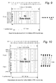
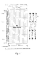
- the TDMA information is carried over the CPRI interface in frames.
- the word length T depends on the total data rate, which is referred to as the CPRI line bit rate.
- Each word corresponds to an 8-bit byte.
- the transmission sequence of the bits is indicated on the right-hand side of Figures 9 to 11 with each ball representing a bit.
- the ten code groups (“ABCDEI FGHJ") are transmitted as a serial data stream with bit "A" first. In 8B/10B encoding, one encoding bit is added to the three most significant bits, and another encoding bit is added to the five least significant bits.
- An AxC container carries an IQ data block in the basic frame. It contains N IQ samples from the same AxC, where N is the oversampling ratio. IQ sample(s) are sent in an AxC container in accordance with either a "packed position" or a "flexible position" in the basic frame. Both are illustrated in Figure 12 . In the packed position, each AxC container in the basic frame is sent consecutively without any reserved bits in between and in descending order of AxC number. For the flexible position, a higher level application decides at what address in the IQ data block the first data bit of the AxC container will be positioned. Bits not used by an AxC container may be treated as reserved bits "r.”
- Figure 13 illustrates a hyperframe structure which is hierarchically embedded between the basic frame and the UMTs radio frame.
- "W" represents the word number in the basic frame
- "Y" represents the byte number within each word.
- the basic frame corresponds to a single chip period in UMTS.
- a hyperframe includes 256 basic frames, with the hyperframe number being designated by the variable X. 256 basic frames in the example implementation corresponds to 66.67 microseconds.
- 150 hyperframes are packed into a single UMTS radio frame, and in the example implementation, the UMTS frame is 10 milliseconds.
- Each hyperframe number is represented by the variable "Z.”
- the hyperframe structure is used to multiplex the different control flows (and sub flows thereof) onto the control time slot.
- the smallest (in terms of bit rate) specified control flow is one control time slot per hyperframe.
- An example of a smallest control flow is the timing marker of the synchronization alignment flow (e.g., a K28.5 symbol).
- the choice of 256 basic frames as one hyperframe provides fine granularity in the allocation of bandwidth to different control flows and also simplifies implementation.
- the data control information are multiplexed together in the basic frame.
- Figure 14 illustrates how multiple antenna carriers AxC 1...AxC N, each having multiple user data (IQ) samples U 1 , U 2 , ..., etc. , are multiplexed with a series of control words (CW) at a first multiplexing level 1.
- each control word corresponds to various control information which has been multiplexed onto the control word stream at a second multiplexing level 2.
- the control information includes timing, layer 1 (L1) signaling, C&M information, and extension information. This corresponds to the logical multiplexing of the different control flows shown in Figure 7 .
- the different timing information and different layer 1 signaling may be multiplexed at a third level 3. This corresponds to a logical multiplexing of the different information within the SYNC and L1 inband signaling 42 shown in Figure 7 . Multiplexing of different applications onto the C&M plane is not shown in Figure 14 .
- control words are preferably organized into subchannels.
- the level 2 multiplexer operates on the subchannels, and each of the four inputs allocates one or more subchannels.
- 64 subchannels are defined.
- Each subchannel includes every 64th control word (CW).
- the first CW in a hyperframe belongs to subchannel 0.
- Each subchannel has 4 CWs within a hyperframe (CW0 - CW3).
- Subchannel 0 has a CW in basic frame numbers 0, 64, 128 and 192 within the hyperframe.
- Subchannel 63 has a CW in basic frame numbers 63, 127, 191 and 255 within the hyperframe.
- This CW organization of a hyperframe is shown in Figure 15 .
- the index for the subchannels ranges from 0 to 63.
- the index (Xs) of a control word within a subchannel has four possible values-0, 1, 2, and 3.
- the level 3 multiplexer of Figure 14 works on the CW level multiplexing up to four sub flows onto one subchannel. The sub flows can be allocated in increments of one CW per hyperframe. Also, the level 3 multiplexer is aligned with the hyperframe start to simplify demultiplexing at the receiving end.
- Subchannel 1 includes the slow C&M link, where the slow C&M link is based on HDLC and has a bandwidth of 0.24, 0.48, or 0.96 Mbps at 1228.8 line bit rate.
- the slow C&M link includes HDLC frames carrying protocol layer L2+ messages.
- Subchannel 2 includes layer 1 in-band protocol information including the interface version, the slow C&M link bit rate (if present), L1 control (e.g., reset of RE, SAP usage, etc.), the L1 status (signal presence and quality, end-point fault, etc.).
- the last control word of subchannel 2 includes a pointer "p" which points to the address/index of the start of fast C&M link, which in this example, is a subchannel number, somewhere in the range between 18 and 61.
- the slow C&M link includes Ethernet frames carrying L2+ messages.
- the fast C&M which uses Ethernet has a bandwidth of 0.96 mbps * N at 1.22.8 line bit rate, where N is the number of subchannels allocated.
- Subchannels 3-15 are reserved for frame or other uses, and subchannels 16 up through the pointer subchannel for the fast C&M include vendor-specific information.
- the vendor specific subchannels allow for add-ons to the protocol to achieve product differentiation.
- subchannel 0 also carries the hyperframe number (HFN in CW 1) and the node B Frame Number (BFN in CW 2 and CW3).
- the BFN identifies a radio frame in the radio signal sent over the air interface.
- Figure 16 illustrates control words and subchannels within one hyperframe.
- the BFN changes every 150 hyperframes/one radio frame.
- the hyperframe number (HFN) is transferred over the radio Uu interface.
- the RE can determine the radio interface (e.g., Uu) frame structure after receiving one hyper frame.
- the current BFN is transferred in whole, and the offset within the radio frame at the start of the received hyperframe is [HFN (received)/150] of a radio frame.
- the L1 signaling transfers a Service Access Point (SAP) Defect Indicator (SDI) bit or the like.
- SDI Service Access Point
- the SDI bit indicates that higher protocol layers (L3 and above up to the application layer) are available and operational on the C&M logical connection, synchronization logical connection, and IQ data logical connection. If the transmitting TDM framer in either the REC or an RE detects that at least one of the logical connection is missing (a fault scenario), the SDI bit is set. Upon detecting a set SDI bit, the receiving node stops interpreting the C&M, the synchronization, and IQ logical connections and enters a "safe state.”
- the fast signaling of a defective link is important because a faulty IQ logical connection or synchronization logical connection may cause transmission of radio signals that do not comply with regulatory requirements. A faulty C&M logical connection may further hinder reconfiguration which in turn can also break such regulatory requirements. Of course, other indicators may be sent to accomplish one or more of these functions.
- L1 signaling such as loss of signal (LOS), loss of frame (LOF), remote alarm indication (RAI), etc.
- L1 signals are read in each RE by its application and signaled to the REC via the application layer.
- layer 1 SDI signals are an exception as the interface is still functioning but the transferred data is temporarily invalid.
- the SDI bit is forwarded to the slave port of a next RE.
- Receiving the SDI informs the next RE that, although the interface is still functioning, the data being transferred is invalid and should be discarded.
- An SDI bit received on a CPRI master port is read by the application in the RE and signaled to the REC via the application layer.
- the RE should not use a faulty link for which the SDI is set for any of the CPRI service access points: IQ, sync, or C&M.
- the RE should prevent any transmission over the radio interface from this faulty link.
- redundant links may be available. Redundancy may exist on a single hop level by using more than one link. Redundancy may also exist on network level.
- An RE can be connected to the REC through more than one logical connection, each logical connection having its own network path. If there are redundant ports by which an RE and the REC may be linked, then the RE may interpret a set SDI such that the information on that link is no longer usable. If redundant information exists, it will be routed instead. But if no redundant information exists, the SDI bit is forwarded to the next RE or the REC.
- the reset function is important but it must also be robust in the sense that false reset triggers should be avoided.
- the reset notification is sent from a master port to a slave port.
- a reset acknowledgement is sent from a slave port to a master port.
- the master wants to reset a slave, it sends the reset signal for at least a predetermined number of hyperframes (e.g., 10), to minimize false resets.
- the slave On the reception of a valid reset notification, the slave sends the reset acknowledgement for at least a predetermined number of hyperframes on the same link, e.g., 5.
- the RE When an RE receives a valid reset notification on any of its slave ports, the RE resets itself and also forwards the reset notification on all its master ports by for at least the predetermined number of hyperframes, e.g., 10. In this way, robust resetting of each RE in the network is ensured.
- the TDM structure requires that both the transmitting node REC/RE and the RE/REC receiving node correctly know when a hyperframe starts. As a result, the receiving node must be able to detect the first basic frame of a hyperframe, the first octet or byte of the first basic frame, and the first bit of the first byte. All three synchronization levels are achieved by sending a unique, known symbol as the first word in a hyperframe.
- a K28.5 symbol which is an 8B/10B code having a total of 10 bits. Two of those bits are redundant bits used for error detection and/or correction. Of course, other known symbols could be used.
- One-fourth of the control subchannel 0, namely, the first control word X 0 may be used to transfer the K28.5 symbol to reduce complexity.
- the RE achieves clock and data recovery.
- the REC defines word borders in the hyperframe. If the receiving node loses data recovery during operation, additional K28.5 symbols are transferred.
- the CPRI interface is self-synchronizing on all levels without the need for feedback from the RE of clock and data recovery status. Nor are special actions needed to regain synchronization other than normal operation of the interface.
- the start-up of the CPRI interface requires minimal start-up information at the REC and RE nodes, i.e., start-up is plug-and-play. This is particularly desirable when radio base stations are deployed in large numbers.
- the start-up procedure must accomplish L1 synchronization bit alignment and hyperframe alignment.
- the REC and the RE (or an RE and another RE) negotiate 3 interface characteristics: the line bit rate of the interface, the protocol revision, and the C&M link characteristics. Since there is no mandatory line bit rate or C&M link characteristics, the REC and REs must, during the start-up procedure, try different configurations until a common match is detected.
- the common match does not have to be optimal. Instead, the first common match permits an exchange of capabilities of a proper configuration to be used in the following communications.
- Figure 17 illustrates start-up state diagram showing various start-up states and transitions. Although described in the context of a start-up between the REC and an RE, the same procedures may be applied for a start-up between to REs.
- An operator may designate a suitable start-up configuration including line bit rate, C&M link characteristics, etc.
- the REC and the RE may also have knowledge about a previous successful configuration.
- state B called "L1 synchronization, and rate negotiation," both REC and RE reach layer 1 (L1) synchronization, and the line bit rate of the interface is determined.
- the REC starts to transmit over the CPRI at the highest available bit rate when first entering the L1 synchronization state and also attempts to receive over the CPRI from the RE at the same line bit rate. If the REC does not reach synchronization, (i.e., the REC does not receive (1) K28.5 symbols at the proper repetition rate-1 per hyperframe-along with (2) an incrementing HFN), it selects another line bit rate after a time interval T1, where the time interval T1 may be, for example, 0.9-1.1 seconds. Following each T1 interval, a new line bit rate for reception and transmission is selected, assuming that one is available.
- the line bit rates may be selected from the available set in a round robin fashion, i.e., the first highest, the second highest,..., the slowest, and restarting from the highest line bit rate.
- the RE attempts to receive over the CPRI at the highest available line bit rate when first entering the L1 synchronization state. If the RE does not reach synchronization, (i.e., the REC does not receive K28.5 symbols at the proper repetition rate-1 per hyperframe-along with an incrementing HFN), it selects another line bit rate after a T1' interval, where T1' may be, for example, between 3.9-4.1 seconds. Following each T1' interval, a new reception line bit rate selected for reception assuming that one is available. Again, the line bit rates may be selected from the available set in a round robin fashion. When the RE reaches synchronization, it starts to transmit over the CPRI interface to the REC at the same line bit rate that it successfully received at. At this point, layer 1 is synchronized with both uplink and downlink hyperframe structures aligned.
- the next start-up state is protocol setup. During this state, a common protocol version of CPRI is determined. If one or both of the REC and RE can use multiple revisions of the CPRI interface, a common revision must be found before trying to extract the conveyed C&M link. Otherwise, the layer 1 signaling (and thus information about possible C&M links) cannot be interpreted.
- the REC and RE negotiate as follows: each node proposes the highest protocol revision that it supports. The node with the proposed highest revision steps back to the same revision as the other node (if possible) or proposes another revision, lower than the other node's (if possible). If one node proposes a revision lower than the lowest revision supported by the other node, no common protocol is available, and the start-up fails. If both nodes propose the same revision, the start-up proceeds using that proposed protocol revision.
- the start-up moves to state C&M plane (L2+) setup to determine a common C&M link bit rate.
- Negotiations proceed in parallel for the fast C&M link and the slow C&M link.
- each node proposes the fastest possible bit rate it supports, i.e., the fastest bit rate supported for fast C&M and the fastest bit rate supported for slow C&M.
- the unit with the highest proposed bit rate steps back to the bit rate proposed by the other node (if possible) or proposes another bit rate lower than that proposed by the other node (if possible).
- the start-up fails.
- the CPRI interface is a "passive link," which can be used in parallel with another interface with has a C&M link, e.g., when the C&M carrying interface does not have enough space for all AxCs to be transferred.
- the passive link state is shown in Figure 17 .
- the start-up proceeds to a vendor-specific negotiation state. During this state, the higher level applications in the REC and RE negotiate the CPRI usage. This specific information exchange about capabilities and capability limitations results in a preferred configuration of the CPRI based on a vendor-specific requirements. At this point, the start-up is complete and normal operation commences.
- the CPRI provides a mechanism to calibrate the delay between the REC and RE and the round trip delay on multi-hop configurations.
- Specific reference points for delay calibration and timing relationships between input and output signals at the RE are defined as shown in Figure 18 .
- the definitions and requirements are described below for a link between REC and an RE, but they also apply for links between two REs if the master port of the REC is replaced by a master port of an RE.
- Reference points R1-R4 for cable delay calibration are the input and output points of the equipment as shown in Figures 18 and 20 .
- Reference points R1-R4 correspond to the output point (R1) and the input point (R4) of the REC, and the input point (R2) and the output point (R3) of an RE terminating a particular logical connection between SAP IQ .
- the antenna is shown as "Ra" for reference.
- Reference points RB 1-4 in the networking RE example shown in Figure 20 correspond to the input point (RB2) and the output point (RB3) of the slave port and the output point (RB 1) and the input point (RB4) of the master port.
- a dashed loop is shown in Figures 18 and 20 corresponding to an REC-to-end-RE loop. It is useful to determine delay associated with the REC-to-end-RE loop for two reasons: (1) to determine a downlink delay from the REC to each RE, which is needed to synchronize the radio/air interface communications for each RE, and (2) determine the uplink delay of the IQ data from each RE to the REC.
- FS frame sync
- FIG 19 shows the relationship between downlink and uplink frame timing.
- T12 is the delay of the downlink signal from the output point of REC (R1) to the input point RE (R2).
- T34 is the delay of the uplink signal from the RE output point (R3) to the REC input (R4).
- Toffset is the frame offset between the RE input at R2 and the RE output signal at R3. The RE determines Toffset. Toffset is either known in advance, or it is measured using the FS #1 transmitted from R1 by the REC. Toffset is the time between receiving the FS #1 at R2 to transmitting the FS #1 at R3 back towards R4.
- This fixed offset is an arbitrary value which is greater than or equal to 0 and less than 256*T c , which in this UMTS example is 66 ⁇ sec.
- T14 is the frame timing difference, (the REC-RE loop delay), between the transmission of the FS #1 from R1 and receipt of the FS #1 at R4 as measured by the REC.
- each RE again determines its Toffset value as in the single hop case and sends it to the REC.
- This fixed offset (Toffset) is an arbitrary value which is greater than or equal to 0 and less than 256*T c . Different REs may use different values for Toffset.
- the interface delay can be determined by each node measuring the difference, Toffset, between the transmitted and received hyperframe structure.
- the RE reports the difference Toffset to the REC as Toffset RE.
- the one-way delay is approximately one-half the round-trip delay.
- the RE generates its transmitted hyperframe number based on the received hyperframe number.
- the Toffset RE is therefore between 0 and 1 hyperframes long.
- Figure 21 shows the relation between downlink and uplink frame timing for the multi-hop configuration example shown in Figure 20 .
- the end-to-end delay definitions (T12, T34 and T14) and the frame timing offset (Toffset) for a multi-hop connection are the same as those of the single-hop connection.
- Each networking RE and end RE provides the REC with a time offset (Toffset (1) and Toffset (2) ).
- Each networking RE having both slave and master ports, also determine and reports the delay TBdelay DL (1) between the slave to master port in the downlink (e.g., RB2-RB1 in Figure 20 ).
- This delay TBdelay DL (1) is determined by finding the time difference between when the frame sync #1 (FS #1) is received on the slave port RB2 and when it is transmitted on the master port RB1. In essence, delay TBdelay DL (1) is the downlink forwarding delay for the networking RE.
- the networking RE also reports to the REC the forwarding delay TBdelay UL (1) between the master to slave port in the uplink (e.g., RB4-RB3 in Figure 20 ). But this uplink forwarding delay TBdelay UL (1) is determined in a different manner than the downlink forwarding delay TBdelay DL (1) because while the downlink forwarding delay TBdelay DL (1) is constant, the uplink forwarding delay TBdelay UL (1) is not. This is because the frame sync FS#1 on the downlink is strictly defined and simply forwarded by the networking REs. But that is not the case with the uplink because the uplink frame structure is more loosely defined and is defined per hop.
- the hop between the end RE and the network uses a frame sync #2, and the hope between the networking RE and the REC uses a frame sync #3.
- the difference between each uplink frame sync is anywhere between 0-66 ⁇ sec in this non-limiting example.
- FS #2 is sent within 66 ⁇ sec of the end RE receiving FS # 1
- FS #3 is sent with 66 ⁇ sec of the networking RE receiving FS #2.
- N The remapping of the data samples from RB4 to RB3 is expressed as "N", which corresponds to the basic frame number on RB4 holding the data sample from the basic frame #0 on RB3.
- N This includes both the relationship between incoming and outgoing FSs as well as the internal processing delay of the networking RE. That delay is denoted as a whole number of basic frames.
- equation (1) is the REC-networking RE loop delay
- equation (2) is the REC-end RE loop delay.
- T ⁇ 14 2 * T ⁇ 12 1 + Toffset
- T ⁇ 14 2 * T ⁇ 12 1 + 2 * T ⁇ 12 2 + TBdelay ⁇ DL 1 + TBdelay ⁇ UL 1 - Tc * N 1 + Toffset 2
- Equations (3) and (4) are two equations with two unknowns (T12 (1) and T12 (2) ), which can thus be solved so that the cable delays between REs can then be determined.
- the downlink delay from the REC to each RE may be determined for use in synchronizing the air interface of each RE.
- this information may be used to determine the uplink delay the IQ data will experience from each RE to the REC.
- the invention can be practiced in a wide variety of implementations and embodiments, and is not limited to the CPRI examples described above. Further details of these particular CPRI example implementations are provided in the CPRI specification v.2.0 described in the U.S. provisional patent application U.S. provisional patent application number 60/617,084 , the contents of which are incorporated herein by reference.
Landscapes
- Engineering & Computer Science (AREA)
- Computer Networks & Wireless Communication (AREA)
- Signal Processing (AREA)
- Mobile Radio Communication Systems (AREA)
Claims (27)
- Ein Verfahren zur Verwendung in einer dezentralen Funkbasisstation (10), umfassend erste und zweite Funkgerät-RE (Radio Equipment)-Knoten (14 a, 14 b) und einen verknüpften Funkgerätesteuerung-REC-Knoten (12), zum Austauschen von Daten zwischen dem Funkgerätesteuerung-REC (Radio Equipment Controller)-Knoten (12) und den ersten und zweiten Funkgeräte-RE-Knoten (14 a, 14 b) zum Übertragen von Sendeinformationen über eine Funkschnittstelle unter Verwendung von mehreren Antennenträgern, wobei der REC-Knoten (12) getrennt von und verknüpft mit dem ersten RE-Knoten (14 a) durch eine erste Sendeverbindung (CPRI-Verbindung) vorgesehen ist und der erste RE-Knoten (14 a) getrennt von und verknüpft mit dem zweiten RE-Knoten (14 b) durch eine zweite Sendeverbindung (CPRI-Verbindung) vorgesehen ist, wobei die erste Sendeverbindung einen Masteranschluss des REC-Knoten (12) mit einem Slaveanschluss des ersten RE-Knoten (14 a) verbindet und die zweite Sendeverbindung einen Masteranschluss des ersten RE-Knoten (14 a) mit einem Slaveanschluss des zweiten RE-Knoten (14 b) verbindet, umfassend die Schritte:Erzeugen von Steuerinformationen und Anwenderinformationen zum Senden über die erste Sendeverbindung von dem REC-Knoten an den ersten RE-Knoten und über die zweite Sendeverbindung von dem ersten RE-Knoten an den zweiten RE-Knoten, wobei die Anwenderinformationen mehrere Datenflüsse umfassen, wobei jeder Datenfluss zu mit einer Antenne verknüpften Daten für einen Funkträger korrespondiert;Formatieren der Steuerinformationen und Anwenderinformationen in mehrere gemultiplexte (Time Divison Multiplexed-TDM) Frames, wobei jeder TDM-Frame einen Steuerzeitschlitz für die Steuerinformationen und mehrere Datenzeitschlitze für die Anwenderinformationen umfasst und jeder Datenzeitschlitz zu einem Datenfluss eines der Antennenträger korrespondiert;Senden von Frames über die erste Sendeverbindung zwischen dem REC-Knoten und dem ersten RE-Knoten;Senden von Frames über die zweite Sendeverbindung zwischen den ersten und zweiten RE-Knoten;Bestimmen einer mit der ersten Sendeverbindung verknüpften ersten Sendezeitverzögerung;Bestimmen einer mit der zweiten Sendeverbindung verknüpften zweiten Sendezeitverzögerung;unter Verwendung der ersten und zweiten Sendeverzögerung in einer Schleifenverzögerungsbestimmung verknüpft mit dem REC-Knoten, dem ersten RE-Knoten und dem zweiten RE-Knoten; undBestimmen eines Frametimingunterschieds korrespondierend zu REC-Ende-RE-Schleife-Verzögerung dazwischen, wenn ein Downlinkframe-Synchronisationssignal von einem Masteranschluss des REC-Knoten gesendet wird, und, wenn ein Uplinkframe-Synchronisationssignal an einem Masteranschluss des REC-Knoten zurück empfangen wird, wobei zumindest die REC-Ende-RE-Schleife-Verzögerung umfasst ist,wobei das Verfahren weiter umfasst:Bereitstellen durch jeden RE-Knoten dem REC-Knoten eines Zeitoffsets zwischen dem Eingabe-Slaveanschluss und Ausgabe-Slaveanschluss des RE-Knotens;Senden durch den REC-Knoten eines ersten Framesynchronisationssignals an den ersten RE-Knoten zu einem ersten Zeitpunkt;Bereitstellen durch den ersten RE-Knoten dem REC-Knoten einer mit einem Empfangen eines ersten Framesynchronisationssignals an dessen Eingang-Slaveanschluss und Senden des ersten Framesynchronisationssignals von dessen Ausgang-Masteranschluss verknüpften Downlinkverzögerung;Bereitstellen durch den ersten RE-Knoten dem REC-Knoten einer mit einem Empfangen eines zweiten Framesynchronisationssignal an dessen Eingang-Masteranschluss und Senden eines dritten Framesynchronisationssignals von dessen Ausgang-Slaveanschluss verknüpften Uplinkverzögerung;Empfangen durch den REC-Knoten des dritten Framesynchronisationssignals zu einem zweiten Zeitpunkt;Bestimmen eines Zeitunterschieds zwischen den ersten und zweiten Zeitpunkten; undBestimmen der mit der ersten Sendeverbindung verknüpften ersten Sendezeitverzögerung und der mit der zweiten Sendeverbindung verknüpften zweiten Sendezeitverzögerung basierend auf dem Zeitunterschied, der Downlinkverzögerung, der Uplinkverzögerung und jedem Zeitoffset.
- Das Verfahren in Anspruch 1 weiter umfassend:Senden über die Radioschnittstelle unter Verwendung eines Code-Division-Multiple-Zugang (Code Division Multiple Access-CDMA),wobei eine Zeitperiode des Frames zu einer CDMA-Chip-Zeitperiode korrespondiert, undwobei eine Senderate über die erste Sendeverbindung andernfalls ungefähr von der Größenordnung 614,3 Mbit/s, 1228,8 Mbit/s oder 2457,6 Mbit/s ist.
- Das Verfahren in Anspruch 1, wobei eine Senderate über die erste Sendeverbindung ungefähr zweimal die Senderate über die zweite Sendeverbindung ist.
- Das Verfahren in Anspruch 1, wobei jeder Antennenträger einen korrespondierenden Zeitschlitz in dem Frame so aufweist, dass Datenproben für jeden Antennenträger in diesen zu dem Antennenträger korrespondierenden Zeitschlitz eingefügt werden, und wobei die korrespondierende Zeitschlitz-Position in dem Frame von einer Position an einem Slaveanschluss des ersten RE-Knoten zu einer anderen Position an einem Masteranschluss des ersten RE-Knoten geändert werden kann.
- Das Verfahren in Anspruch 1, wobei die Steuerinformationen eine Schicht-1 (Layer 1-L1)-Signalisierung umfasst, wobei die L1-Signalisierung einen Dienstzugangspunkt-Fehler-Indikator (Service Access Point Defect Indicator-SDI) umfasst, welcher angibt, ob höhere Schichten für Daten, eine Synchronisation oder eine Steuerung und Verwaltung (Control und Management-C&M) betreibbar sind.
- Das Verfahren in Anspruch 5, wobei, wenn der erste RE-Knoten den SDI über die erste Sendeverbindung empfängt, der erste RE-Knoten die über die erste Sendeverbindung empfangenen Daten ignoriert und den SDI über die zweite Sendeverbindung an den zweiten RE-Knoten weiterleitet.
- Das Verfahren in Anspruch 5, wobei, wenn der erste RE-Knoten den SDI über die erste Sendeverbindung empfängt, der erste RE-Knoten auf einer redundanten ersten Sendeverbindung empfangene Daten über die zweite Sendeverbindung sendet.
- Das Verfahren in Anspruch 1, wobei, falls die durch den REC-Knoten gesendeten Steuerinformationen einen Reset-Indikator umfassen, der erste RE-Knoten eine Resetoperation für den ersten RE-Knoten einleitet und ebenso den Reset-Indikator an den zweiten RE-Knoten sendet.
- Das Verfahren den Anspruch 1, wobei einer der Knoten mehrere Masteranschlüsse oder mehrere Slaveanschlüsse umfasst und wobei die Senderate über manche der Anschlüsse unterschiedlich ist.
- Eine dezentrale Funkbasisstation (10) umfassend:einen Funkgerätesteuereinheit-REC-Knoten (12);einen ersten Funkgerät-RE-Knoten (14 a), umfassend ein oder mehrere Antennenelemente;einen zweiten Funkgerät-RE-Knoten (14 a), umfassend ein oder mehrere Antennenelemente;eine erste Kommunikationsverbindung (CPRI-Verbindung), welche eine Kommunikation zwischen dem REC-Knoten und dem ersten RE-Knoten erlaubt;eine zweite Kommunikationsverbindung (CPRI-Verbindung), welche eine Kommunikation zwischen dem ersten RE-Knoten und dem zweiten RE-Knoten erlaubt;eine Kommunikationsschnittstelle (CPRI), welche ein Kommunikationsprotokoll für die ersten und zweiten Kommunikationsverbindungen bestimmt;wobei die erste Verbindung einen Masteranschluss des REC-Knoten (12) mit einem Slaveanschluss des ersten RE-Knoten (14 a) verbindet und die zweite Verbindung einen Masteranschluss des ersten RE-Knoten (14 a) mit einem Slaveanschluss des zweiten RE-Knoten (14 b) verbindet,wobei der REC-Knoten umfasst:eine REC-Steuereinheit (70) zum Bereitstellen von Steuerinformationen und Anwenderinformationen zum Senden über die erste Kommunikationsverbindung an den ersten RE-Knoten, wobei die Anwenderinformationen mehrere Datenflüsse umfassen, wobei jeder Datenfluss zu mit einer Antenne für einen Träger verknüpften Daten korrespondiert;einen REC-Framer (72) zum Formatieren der Steuerinformationen und Anwenderinformationen in mehrere Frames, wobei jeder Frame einen Steuerzeitschlitz für die Steuerinformationen und mehrere Datenzeitschlitze für die Anwenderinformationen umfasst und jeder Datenzeitschlitz zu einem Datenfluss von einem von mehreren Antennenträgern korrespondiert; undeinen REC-Transmitter (76) zum Senden von Frames über die erste Kommunikationsverbindung an den ersten RE-Knoten;wobei der erste RE-Knoten zum Empfangen der Steuerinformationen und Anwenderinformationen von dem REC-Knoten für den zweiten RE-Knoten über die erste Kommunikationsverbindung ausgebildet ist, wobei die Anwenderinformationen mehrere Datenflüsse umfassen, wobei jeder Datenfluss zu mit einer Antenne für einen Träger verknüpften Daten korrespondiert, wobei der erste RE-Knoten umfasst:Funkschaltkreise (85 a);einen ersten RE-Framer (82 a) zum Formatieren von Steuerinformationen und Anwenderinformationen in mehreren Frames, wobei jeder Frame einen Steuerzeitschlitz für die Steuerinformationen und mehrere Datenzeitschlitze für die Anwenderinformationen umfasst und jeder Datenzeitschlitz zu einem Datenfluss von einem von mehreren Antennenträgern korrespondiert, wobei der erste RE-Framer zum Führen einer ersten RE-Steuerung und Anwenderinformationen zu und von den Funkschaltkreisen und zum Weiterleiten einer zweiten RE-Steuerung und Anwenderinformationen zu und von dem zweiten RE-Knoten ausgebildet ist; undeinen ersten RE-Transmitter (86 a) zum Senden von Frames über die erste Kommunikationsverbindung,wobei die dezentrale Funkbasisstation weiter umfasst:Mittel (80 a) zum Bestimmen einer mit der ersten Sendeverbindung verknüpften ersten Sendezeitverzögerung;Mittel (80 b) zum Bestimmen einer mit der zweiten Sendeverbindung verknüpften zweiten Sendezeitverzögerung;Mittel (70) zum Verwenden der ersten und zweiten Sendeverzögerungen in einer Schleifenverzögerung-Bestimmung verknüpft mit dem REC-Knoten, dem ersten RE-Knoten und dem zweiten RE-Knoten; undelektronische Schaltkreise (70), ausgebildet zum Bestimmen eines Frametimingunterschieds zwischen korrespondierend zu einem REC-Ende-RE-Schleifen-Verzögerung, wenn ein Downlinkframe-Synchronisationssignal von einem Masteranschluss des REC-Knoten gesendet wird, und, wenn ein Uplinkframe-Synchronisationssignal an einem Masteranschluss des REC-Knoten zurück empfangen wird, wobei zumindest die REC-Ende-REC-Schleifenverzögerung umfasst ist,wobei jeder RE-Knoten zum Bereitstellen an den REC-Knoten eines Zeitoffsets zwischen dem Eingang-Slaveanschluss und Ausgang-Slaveanschluss des RE-Knotens ausgebildet ist,der REC-Knoten zum Senden eines ersten Framesynchronisationssignals an den ersten RE-Knoten zu einem ersten Zeitpunkt ausgebildet ist;der erste RE-Knoten zum Bereitstellen an den REC-Knoten eine mit einem Empfangen eines ersten Framesynchronisationssignals an dem Eingang-Slaveanschluss des ersten RE-Knotens und Senden des ersten Framesynchronisationssignals an dem Ausgang-Masteranschluss des ersten RE-Knotens verknüpfte Downlinkverzögerung ausgebildet ist;der erste RE-Knoten zum Bereitstellen an den REC-Knoten einer mit einem Empfangen eines zweiten Framesynchronisationssignals an dem Eingang-Masteranschluss des ersten RE-Knotens und Senden eines dritten Framesynchronisationssignals an dem Ausgang-Slaveanschluss des ersten RE-Knotens verknüpfte Uplinkverzögerung ausgebildet ist;der REC-Knoten zum Empfangen von dem ersten RE-Knoten das dritte Framesynchronisationssignal zu einem zweiten Zeitpunkt, Bestimmen eines Zeitunterschieds zwischen den ersten und zweiten Zeitpunkten und Bestimmen der mit der ersten Sendeverbindung verknüpften ersten Sendezeitverzögerung und der mit der zweiten Sendeverbindung verknüpften zweiten Sendezeitverzögerung basierend auf dem Zeitunterschied, der Downlinkverzögerung, der Uplinkverzögerung und jedem Zeitoffset ausgebildet ist.
- Die Funkbasisstation in Anspruch 10, wobei jeder Antennenträger einen korrespondierenden Zeitschlitz in dem Frame so aufweist, dass Datenproben für jeden Antennenträger in diesen zu dem Antennenträger korrespondierenden Zeitschlitz eingefügt werden und wobei die korrespondierende Zeitschlitz-Position in dem Frame von einer Position an einem Slaveanschluss des ersten RE-Knoten, welcher Downlink-Informationen empfängt, zu einer anderen Position an einem Masteranschluss des ersten RE-Knoten, welcher Uplink-Informationen empfängt, geändert werden kann.
- Die Funkbasisstation in Anspruch 10, wobei die Steuerinformationen Schicht-1-L1 (Layer 1)-Signalisierung umfasst, wobei die L1-Signalisierung einen Dienstzugangspunkt-Fehler-Indikator (Service Access Point Defect Indicator-SDI) umfasst, welcher angibt, ob höhere Schichten für Daten, eine Synchronisation oder eine Steuerung und Verwaltung (Control und Management) C&M betreibbar sind.
- Die Funkbasisstation in Anspruch 12, wobei der erste RE-Knoten zum Empfangen des SDI über die erste Sendeverbindung ausgebildet ist und in Reaktion auf ein Empfangen des SDI über die erste Sendeverbindung der erste RE-Knoten zum Ignorieren der über die erste Sendeverbindung empfangenen Daten und Weiterleiten des SDI über die zweite Sendeverbindung an den zweiten RE-Knoten ausgebildet ist.
- Die Funkbasisstation in Anspruch 12, wobei der erste RE-Knoten zum Empfangen des SDI über die erste Sendeverbindung ausgebildet ist und in Reaktion auf ein Empfangen des SDI über die erste Sendeverbindung der erste RE-Knoten zum Senden von auf einer redundanten ersten Sendeverbindung empfangenen Daten über die zweite Sendeverbindung ausgebildet ist.
- Die Funkbasisstation in Anspruch 12, wobei, falls die durch den REC-Knoten gesendeten Steuerinformationen einen Reset-Indikator umfassen, der erste RE-Knoten zum Einleiten einer Resetoperation für den ersten RE-Knoten und Senden des Reset-Indikators an den zweiten RE-Knoten ausgebildet ist.
- Eine Funkgerätesteuereinheit REC (12) zur Verwendung in einer dezentralen Funkbasisstation (10), welche erste und zweite Funkgeräte (RE)-Einheiten (14 a, 14 b) umfasst, welche jeweils ein oder mehrere Antennenelemente aufweisen, wobei die REC getrennt von und verknüpften mit dem ersten RE durch eine erste Sendeverbindung (CPRI-Verbindung) vorgesehen ist und die erste RE getrennt von und verknüpft mit der zweiten RE durch eine zweite Sendeverbindung (CPRI-Verbindung) vorgesehen ist, wobei die erste Sendeverbindung einen Masteranschluss des REC (12) mit einem Slaveanschluss des ersten RE (14 a) verbindet und die zweite Sendeverbindung einen Masteranschluss des ersten RE (14 a) mit einem Slaveanschluss des zweiten RE (14 b) verbindet, wobei die REC umfasst:eine Steuereinheit (70) zum Bereitstellen von Steuerinformationen und Anwenderinformationen zum Senden über die ersten und zweiten Kommunikationsverbindungen entsprechend an die ersten und zweiten REs, wobei die Anwenderinformationen mehrere Datenflüsse umfassen, wobei jeder Datenfluss zu einer Antenne für einen Träger verknüpften Daten korrespondiert;einen Framer (72) zum Formatieren der Steuerinformationen und Anwenderinformationen in mehrere gemultiplexte (Time Divison Multiplexed-TDM) Frames, wobei jeder TDM-Frame einen Steuerzeitschlitz für die Steuerinformationen und mehrere Datenzeitschlitze für die Anwenderinformationen umfasst und jeder Datenzeitschlitz zu einem Datenfluss von einem von mehreren Antennenträgern korrespondiert; undeinen Transmitter (76) zum Senden von Frames über die erste Kommunikationsverbindung, welche für den ersten RE und den zweiten RE gedacht sind, wobei die für den zweiten RE gedachten Frames an die erste RE zum Senden durch die erste RE an die zweite RE über die zweite Kommunikationsverbindung gesendet werden,wobei die Steuereinheit ausgebildet ist zum:Bestimmen einer mit der ersten Sendeverbindung verknüpften ersten Sendezeitverzögerung;Bestimmen einer mit der zweiten Sendeverbindung verknüpften zweiten Sendezeitverzögerung;Verwenden der ersten und zweiten Sendeverzögerung in einer Schleifenverzögerungsbestimmung verknüpft mit dem REC-Knoten, dem ersten RE-Knoten und dem zweiten RE-Knoten; undBestimmen eines Frametimingunterschieds korrespondierend zu REC-Ende-RE-Schleife-Verzögerung dazwischen, wenn ein Downlinkframe-Synchronisationssignal von einem Masteranschluss des REC gesendet wird, und, wenn ein Uplinkframe-Synchronisationssignal an einem Masteranschluss des REC zurück empfangen wird, wobei zumindest die REC-Ende-RE-Schleife-Verzögerung umfasst ist,wobei die REC ausgebildet ist zum:Senden eines ersten Framesynchronisationssignals an das erste RE zu einem ersten Zeitpunkt, wenn jedes RE dem REC ein Zeitoffset zwischen dem Eingabe-Slaveanschluss und Ausgabe-Slaveanschluss des RE bereitstellt;Empfangen einer Downlinkverzögerung von der ersten RE, welche mit einem Empfangen eines ersten Framesynchronisationssignal an dem Eingang-Slaveanschluss des ersten RE und ein Senden des ersten Framesynchronisationssignals an dem Ausgang-Masteranschluss des ersten RE verknüpft ist;Empfangen einer Uplinkverzögerung von dem ersten RE, welche mit einem Empfangen eines zweiten Framesynchronisationssignals an dem Eingang-Masteranschluss des ersten RE und Senden eines Dritten Framesynchronisationssignals an dem Ausgang-Slaveanschluss des ersten RE verknüpft ist;Empfangen des dritten Framesynchronisationssignals zu einem zweiten Zeitpunkt von dem ersten RE;Bestimmen eines Unterschieds zwischen den ersten und zweiten Zeitpunkten; undBestimmen der mit der ersten Sendeverbindung verknüpften ersten Sendezeitverzögerung und der mit der zweiten Sendeverbindung verknüpften zweiten Sendezeitverzögerung basierend auf dem Zeitunterschied, der Downlinkverzögerung, der Uplinkverzögerung und jedem Zeitoffset.
- Die REC in Anspruch 16, wobei eine Senderate über die erste Sendeverbindung ungefähr von der Größenordnung 614,3 Mbit/s, 1228,8 Mbit/s oder 2457,6 Mbit/s ist.
- Die REC in Anspruch 16, wobei jeder Antennenträger einen korrespondierenden Zeitschlitz in dem Frame so aufweist, dass Datenproben für jeden Antennenträger in diesen zu dem Antennenträger korrespondierenden Zeitschlitz eingefügt werden und wobei die korrespondierende Zeitschlitz-Position in dem Frame von einer Position an einem Slaveanschluss des ersten RE, welcher Downlink-Informationen empfängt, zu einer anderen Position an einem Masteranschluss des ersten RE, welcher Uplink-Informationen empfängt, geändert werden kann.
- Die REC in Anspruch 16, wobei die Steuerinformationen Schicht-1-L1 (Layer 1)-Signalisierung umfasst, wobei die L1-Signalisierung einen Dienstzugangspunkt-Fehler-Indikator (Service Access Point Defect Indicator-SDI) umfasst, welcher angibt, ob höhere Schichten für Daten, eine Synchronisation oder eine Steuerung und Verwaltung (Control und Management-C&M) betreibbar sind.
- Ein Funkgerät RE (14 a) zur Verwendung in einer dezentralen Funkbasisstation (10), welche ein anderes RE (14 b) und eine Funkgerätesteuereinheit REC (12), welche mit dem RE durch eine erste Kommunikationsverbindung (CPRI-Verbindung) verbunden ist und zu dem anderen RE durch eine zweite Kommunikationsverbindung (CPRI-Verbindung) verbunden ist, umfasst, wobei die erste Verbindung einen Masteranschluss des REC (12) mit einem Slaveanschluss des RE (14 a) verbindet und die zweite Verbindung einen Masteranschluss des RE (14 a) mit einem Slaveanschluss des anderen RE (14 b) verbindet, wobei das RE umfasst:Funksendeschaltkreise (85 a), verknüpft mit einem oder mehreren Antennenelementen zum Empfangen von Steuerinformationen und Anwenderinformationen zum Senden über die erste Kommunikationsverbindung an die REC, wobei Anwenderinformationen mehrere Datenflüsse umfassen, wobei jeder Datenfluss zu mit einem Antennenelement für einen Träger verknüpften Daten korrespondiert;erste Schnittstellen-Schaltkreise (88 a) zum Empfangen von Steuerinformationen und Anwenderinformationen umfassenden Frames für die REC von dem anderen RE über die zweite Kommunikationsverbindung, wobei die Steuerinformationen mehrere Datenflüsse umfassen, wobei jeder Datenfluss zu mit einem Antennenelement für einen Träger verknüpften Daten korrespondiert, und jeder Frame einen Steuerzeitschlitz für die Steuerinformationen und mehrere Datenzeitschlitze für die Anwenderinformationen umfasst und jeder Datenzeitschlitz zu einem Datenfluss von einem von mehreren Antennenträgern korrespondiert;Verarbeitungschaltkreise (80 a) zum Formatieren der Steuerinformationen und Anwenderinformationen von den Funksendeschaltkreisen in mehrere Frames; undzweite Schnittstellen-Schaltkreise (86 a) ausgebildet zum Senden von Frames über die erste Kommunikationsverbindung zu der REC, wobei die Frames von den Funksendeschaltkreisen und von der anderen RE empfangenen Steuer- und Anwenderinformationen umfassen,wobei die Verarbeitungschaltkreise ausgebildet sind zum:Bereitstellen von Informationen zum Bestimmen einer ersten mit der ersten Sendeverbindung verknüpften ersten Sendezeitverzögerung, undBereitstellen von Informationen zum Bestimmen einer mit der zweiten Sendeverbindung verknüpften Sendezeitverzögerung,wobei eine mit der REC, dem ersten RE und dem zweiten RE verknüpften Schleifenverzögerung basierend auf den ersten und zweiten Sendeverzögerungen berechenbar ist; unddie Verarbeitungschaltkreise zum Bereitstellen von Informationen zum Bestimmen eines Frametimingunterschieds korrespondierend zu einer REC-Ende-RE-Schleifenverzögerung dazwischen, wenn ein Downloadlinkframe-Synchronisationssignal von einem Masteranschluss der REC gesendet wird, und, wenn ein Uplinkframe-Synchronisationssignal an einem Masteranschluss der REC zurück empfangen wird, wobei zumindest die REC-Ende-RE-Schleifenverzögerung umfasst ist,wobei das RE zum Bereitstellen an die REC eines Zeitoffset zwischen dem Eingabe-Slaveanschluss und Ausgabe-Slaveanschluss des RE ausgebildet ist und in Reaktion auf ein Empfangen eines an das RE zu einem ersten Zeitpunkt gesendete ersten Framesynchronisationssignals das RE zum Bereitstellen an die REC einer mit einem Empfangen eines ersten Framesynchronisationssignals an dem Eingang-Slaveanschluss des RE und Senden des ersten Framesynchronisationssignals an dem Ausgang-Masteranschluss des RE verknüpften Downlinkverzögerung und einer mit einem Empfangen eines zweiten Framesynchronisationssignals an dem Eingang-Masteranschluss des RE und Senden eines Dritten Framesynchronisationssignals an dem Ausgang-Slaveanschluss des RE verknüpften Uplinkverzögerung ausgebildet ist.
- Das RE in Anspruch 20, wobei die zweiten Schnittstellen-Schaltkreise zum Empfangen von Frames von der REC ausgebildet sind, und
wobei die Verarbeitungschaltkreise zum Führen von manchen der empfangenen Frames zu den Funksendeschaltkreisen zum Senden über die Funkschnittstelle und zum Führen von anderen der empfangenen Frames an die ersten Schnittstellen-Schaltkreise zum Übermitteln an die andere RE über die zweite Kommunikationsverbindung ausgebildet sind. - Das RE in Anspruch 21, wobei die Verarbeitungschaltkreise einen Framer/Deframer (82 a) umfassen und die ersten und zweiten Schnittstellen-Schaltkreise jeweils einen Serialisierer/De-Serialisierer umfassen.
- Das RE in Anspruch 20, wobei jeder Antennenträger einen entsprechenden Zeitschlitz in dem Frame so aufweist, dass Datenproben für jeden Antennenträger von diesen zu dem Antennenträger korrespondierenden Zeitschlitz eingefügt werden und wobei die korrespondierenden Zeitschlitzpositionen in dem Frame von einer Position an einem Slaveanschluss des RE zu einer anderen Position an einem Masteranschluss des RE geändert werden können.
- Das RE in Anspruch 20, wobei die Steuerinformationen Schicht-1-L1 (Layer 1)-Signalisierung umfasst, wobei die L1-Signalisierung einen Dienstzugangspunkt-Fehler-Indikator (Service Access Point Defect Indicator-SDI) umfasst, welcher angibt, ob höhere Schichten für Daten, eine Synchronisation oder eine Steuerung und Verwaltung (Control und Management) C&M betreibbar sind.
- Das RE in Anspruch 24, wobei, wenn das RE den SDI über die erste Sendeverbindung empfängt, das erste RE zum Ignorieren der über die erste Sendeverbindung empfangenen Daten und zum Weiterleiten des SDI an die ersten Schnittstellen-Schaltkreise zum Senden über die zweite Sendeverbindung an das andere RE ausgebildet ist.
- Das RE in Anspruch 24, wobei, wenn das RE den SDI über die erste Sendeverbindung empfängt, das RE zum Senden von auf einer redundanten ersten Sendeverbindung empfangenen Daten über die Funkschnittstelle und/oder die zweite Sendeverbindung ausgebildet ist.
- Das RE in Anspruch 20, wobei, falls die durch die REC gesendeten Steuerinformationen einen Reset-Indikator umfassen, das RE zum Einleiten einer Resetoperation für das RE und zum Senden des Reset-Indikators an das andere RE ausgebildet ist.
Applications Claiming Priority (2)
| Application Number | Priority Date | Filing Date | Title |
|---|---|---|---|
| US61708404P | 2004-10-12 | 2004-10-12 | |
| PCT/IB2005/003036 WO2006040653A1 (en) | 2004-10-12 | 2005-10-12 | Communication between a radio equipment control node and multiple remote radio equipment nodes |
Publications (2)
| Publication Number | Publication Date |
|---|---|
| EP1810534A1 EP1810534A1 (de) | 2007-07-25 |
| EP1810534B1 true EP1810534B1 (de) | 2015-06-17 |
Family
ID=35530824
Family Applications (1)
| Application Number | Title | Priority Date | Filing Date |
|---|---|---|---|
| EP05795927.2A Expired - Lifetime EP1810534B1 (de) | 2004-10-12 | 2005-10-12 | Kommunikation zwischen einem funkgeräte -steuerknoten und mehreren abgesetzten funkgeräte-knoten |
Country Status (7)
| Country | Link |
|---|---|
| US (1) | US8908650B2 (de) |
| EP (1) | EP1810534B1 (de) |
| JP (1) | JP5033940B2 (de) |
| CN (1) | CN101107871B (de) |
| CA (1) | CA2582065C (de) |
| ES (1) | ES2550104T3 (de) |
| WO (1) | WO2006040653A1 (de) |
Families Citing this family (136)
| Publication number | Priority date | Publication date | Assignee | Title |
|---|---|---|---|---|
| JP2913457B2 (ja) | 1994-08-02 | 1999-06-28 | 青木 均次 | 燻蒸殺虫器 |
| US8380143B2 (en) | 2002-05-01 | 2013-02-19 | Dali Systems Co. Ltd | Power amplifier time-delay invariant predistortion methods and apparatus |
| US8811917B2 (en) | 2002-05-01 | 2014-08-19 | Dali Systems Co. Ltd. | Digital hybrid mode power amplifier system |
| CN1859396A (zh) * | 2006-02-06 | 2006-11-08 | 华为技术有限公司 | 通用无线接口传输多体制无线业务数据的方法 |
| DE102006019475B4 (de) | 2006-04-26 | 2008-08-28 | Nokia Siemens Networks Gmbh & Co.Kg | Verfahren zur Synchronisation von Baugruppen einer Basisstation |
| EP1858276B8 (de) * | 2006-05-15 | 2018-05-02 | Nokia Solutions and Networks GmbH & Co. KG | Schnittstelle zur effizienten Übertragung von digitalen Signalen |
| JP4981494B2 (ja) * | 2006-05-30 | 2012-07-18 | 株式会社日立国際電気 | 無線通信システム及び張り出し局装置 |
| JP4791320B2 (ja) * | 2006-10-13 | 2011-10-12 | 富士通株式会社 | コモン・パブリック・ラジオ・インタフェース(cpri)のベンダー特有領域を使った回線迂回方式 |
| KR20100014339A (ko) | 2006-12-26 | 2010-02-10 | 달리 시스템즈 씨오. 엘티디. | 다중 채널 광대역 통신 시스템에서의 기저 대역 전치 왜곡 선형화를 위한 방법 및 시스템 |
| JP4814992B2 (ja) * | 2007-03-16 | 2011-11-16 | 富士通株式会社 | 基地局、無線制御装置、無線装置およびデータ転送方法 |
| JP4807453B2 (ja) * | 2007-03-28 | 2011-11-02 | 富士通株式会社 | 無線制御装置と無線装置間のデータ通信方法、無線制御装置、および、無線装置 |
| CN101111049B (zh) * | 2007-08-14 | 2010-07-28 | 华为技术有限公司 | 实现一个小区覆盖多区域的系统、方法和网络设备 |
| CN101409667B (zh) * | 2007-10-12 | 2011-08-24 | 中国移动通信集团公司 | 无线电基站中的数据交互方法、设备及系统 |
| CN101175291B (zh) * | 2007-11-21 | 2010-09-29 | 中兴通讯股份有限公司 | 对BBU上连接的RRU进行AxC的分配方法及装置 |
| JP5256298B2 (ja) * | 2007-11-21 | 2013-08-07 | テレフオンアクチーボラゲット エル エム エリクソン(パブル) | 通信システムにおける方法及び無線基地局 |
| GB2455702B (en) | 2007-11-29 | 2012-05-09 | Ubidyne Inc | A method and apparatus for autonomous port role assignments in master-slave networks |
| EP2232942B1 (de) * | 2008-01-17 | 2018-05-02 | Telefonaktiebolaget LM Ericsson (publ) | Asynchrone kommunikation über eine gemeinsame öffentliche funkschnittstelle (cpri) |
| JP4951537B2 (ja) * | 2008-01-18 | 2012-06-13 | 株式会社日立製作所 | 無線通信ネットワークおよび無線基地局装置および無線通信ネットワークにおける通信方法 |
| CN101500338B (zh) * | 2008-01-28 | 2011-07-20 | 华为技术有限公司 | 一种通用公共无线接口上进行通道校正的方法和系统 |
| CN101527959B (zh) * | 2008-03-03 | 2012-09-05 | 中兴通讯股份有限公司 | 时钟同步系统 |
| JP5146037B2 (ja) * | 2008-03-19 | 2013-02-20 | 富士通株式会社 | 無線制御装置、無線装置、および通信システム |
| US8050296B2 (en) | 2008-03-31 | 2011-11-01 | Telefonaktiebolaget Lm Ericsson (Publ) | Radio equipment (RE)-based synchronization |
| CN101282517A (zh) * | 2008-05-08 | 2008-10-08 | 华为技术有限公司 | 多模基站及其通信方法 |
| JP5131026B2 (ja) * | 2008-05-20 | 2013-01-30 | 富士通株式会社 | 無線基地局システム並びに制御装置及び無線装置 |
| WO2010013332A1 (ja) * | 2008-07-30 | 2010-02-04 | 富士通株式会社 | データ中継装置および当該データ中継装置によるフレーム処理方法 |
| EP2348648A4 (de) * | 2008-10-14 | 2015-02-11 | Fujitsu Ltd | Relaiseinrichtung, relaisverfahren und relaisprogramm |
| CN101369972B (zh) * | 2008-10-17 | 2013-06-12 | 华为技术有限公司 | 业务数据传输方法、系统及设备 |
| JP5135171B2 (ja) * | 2008-11-10 | 2013-01-30 | 株式会社エヌ・ティ・ティ・ドコモ | 無線基地局、無線装置及び無線装置制御装置 |
| CN102395227B (zh) * | 2008-12-17 | 2014-09-17 | 华为技术有限公司 | 通信信号的多路复用方法、无线通信系统及无线设备控制器 |
| CN101489156B (zh) * | 2008-12-17 | 2011-11-16 | 华为技术有限公司 | 通信信号的多路复用方法、无线通信系统及无线设备控制器 |
| WO2010082333A1 (ja) * | 2009-01-15 | 2010-07-22 | 富士通株式会社 | 無線基地局装置及び遅延補正方法 |
| JP5216604B2 (ja) * | 2009-01-19 | 2013-06-19 | 株式会社日立国際電気 | 無線装置 |
| CN102293030B (zh) * | 2009-01-20 | 2014-04-23 | 株式会社Ntt都科摩 | 无线基站、无线装置控制装置以及无线装置 |
| JP5302051B2 (ja) * | 2009-03-05 | 2013-10-02 | 京セラ株式会社 | 無線基地局、無線制御装置及び無線装置 |
| JP5282618B2 (ja) * | 2009-03-24 | 2013-09-04 | 富士通株式会社 | 無線基地局装置及びその同期方法 |
| US8849328B2 (en) | 2009-04-03 | 2014-09-30 | Huawei Technologies Co., Ltd. | Base station sharing |
| US8346091B2 (en) | 2009-04-29 | 2013-01-01 | Andrew Llc | Distributed antenna system for wireless network systems |
| JP5375320B2 (ja) * | 2009-05-08 | 2013-12-25 | 富士通株式会社 | 通信制御方法、通信システム及び通信装置 |
| JP5187443B2 (ja) * | 2009-05-27 | 2013-04-24 | 富士通株式会社 | 無線装置制御装置、無線装置、および通信方法 |
| CN102450046A (zh) * | 2009-06-03 | 2012-05-09 | 华为技术有限公司 | 拥有多个逻辑基站的基站 |
| CN101998616B (zh) | 2009-08-31 | 2014-05-14 | 国际商业机器公司 | 无线通信系统基站及其数据传输的同步方法 |
| CN101695175B (zh) | 2009-10-28 | 2013-05-08 | 中兴通讯股份有限公司 | 级联设备告警上报方法、系统和设备 |
| JP2011114689A (ja) * | 2009-11-27 | 2011-06-09 | Fujitsu Ltd | 無線基地局装置 |
| JP5338648B2 (ja) * | 2009-12-16 | 2013-11-13 | 富士通株式会社 | 無線基地局、無線制御装置及び無線装置、並びに通信方法 |
| JP5193990B2 (ja) * | 2009-12-17 | 2013-05-08 | 株式会社エヌ・ティ・ティ・ドコモ | 中継装置 |
| JP5174799B2 (ja) * | 2009-12-17 | 2013-04-03 | 株式会社エヌ・ティ・ティ・ドコモ | 無線基地局システム及び中継装置 |
| JPWO2011074664A1 (ja) * | 2009-12-18 | 2013-05-02 | 株式会社エヌ・ティ・ティ・ドコモ | 無線基地局及び中継装置 |
| CN102131248B (zh) * | 2010-01-19 | 2013-12-04 | 华为技术有限公司 | 一种速率协商方法及数据传输系统以及相关设备 |
| KR101674209B1 (ko) * | 2010-01-27 | 2016-11-08 | 삼성전자주식회사 | 디지털 장치와 rf 장치간에 이더넷 데이터를 송수신하는 방법 및 그 장치 |
| CN102143611B (zh) * | 2010-02-02 | 2014-06-11 | 中兴通讯股份有限公司 | 一种射频拉远单元及其光口上下联自适应方法 |
| JP5521739B2 (ja) * | 2010-04-26 | 2014-06-18 | 富士通株式会社 | 通信システム、キャリア側通信装置、基地局装置および通信方法 |
| JP5041035B2 (ja) * | 2010-06-04 | 2012-10-03 | 住友電気工業株式会社 | 無線装置及び無線基地局装置 |
| US8848766B2 (en) | 2010-08-17 | 2014-09-30 | Dali Systems Co. Ltd. | Neutral host architecture for a distributed antenna system |
| JP5859538B2 (ja) * | 2010-08-17 | 2016-02-10 | ダリ システムズ カンパニー リミテッド | 遠隔で再構成可能な分散型アンテナシステム及び分散型アンテナ方法 |
| CN101938768B (zh) | 2010-08-20 | 2012-12-19 | 华为技术有限公司 | 级联rcu链路扫描的方法和电调天线系统 |
| KR102136940B1 (ko) | 2010-09-14 | 2020-07-23 | 달리 시스템즈 씨오. 엘티디. | 원격으로 재구성가능한 분산 안테나 시스템 및 방법 |
| CN103201958B (zh) | 2011-02-07 | 2017-01-18 | 大力系统有限公司 | 用于分布式天线系统的远程单元的菊花链式环 |
| US8731002B2 (en) * | 2011-03-25 | 2014-05-20 | Invensense, Inc. | Synchronization, re-synchronization, addressing, and serialized signal processing for daisy-chained communication devices |
| EP2515603B1 (de) | 2011-05-25 | 2015-09-09 | Huawei Technologies Co., Ltd. | Verbesserte Übertragungsorganisation auf einer CPRI-Schnittstelle eines Node B |
| EP2719138B1 (de) | 2011-06-09 | 2020-05-20 | CommScope Technologies LLC | Schnittstelle eines verteilten antennensystems zur verarbeitung von digitalen signalen in einem standardisierten format |
| WO2012171133A1 (en) * | 2011-06-13 | 2012-12-20 | Telefonaktiebolaget L M Ericsson (Publ) | Method and device for rate matching |
| CN102857958B (zh) * | 2011-06-30 | 2017-09-29 | 南京中兴新软件有限责任公司 | 一种测试rru上行链路时延的方法及系统 |
| CN102307368B (zh) | 2011-09-02 | 2017-12-26 | 中兴通讯股份有限公司 | 环网无线设备的倒换方法及系统 |
| US9036544B2 (en) * | 2011-10-25 | 2015-05-19 | Telefonaktiebolaget L M Ericsson (Publ) | Delay compensation during synchronization in a base station in a cellular communication network |
| KR102012246B1 (ko) * | 2011-11-10 | 2019-08-21 | 한국전자통신연구원 | 무선 기지국 및 그의 데이터 처리 방법 |
| CA2864279C (en) * | 2012-02-09 | 2019-06-11 | Telefonaktiebolaget Lm Ericsson (Publ) | A network node and a method therein enabling a first unit to connect or to be connected ad-hoc to a second unit |
| CN103260198A (zh) * | 2012-02-17 | 2013-08-21 | 中兴通讯股份有限公司 | 分布式基站传输速率的动态配置、匹配方法及装置 |
| WO2013139367A1 (en) * | 2012-03-19 | 2013-09-26 | Telefonaktiebolaget L M Ericsson (Publ) | Wdm link for radio base station |
| CN102723994B (zh) * | 2012-06-15 | 2016-06-22 | 华为技术有限公司 | 数据传输的方法、装置及系统 |
| CN104471410B (zh) * | 2012-07-20 | 2017-05-17 | 日产自动车株式会社 | 故障诊断系统以及故障诊断方法 |
| CN103580780B (zh) * | 2012-07-23 | 2018-03-09 | 中兴通讯股份有限公司 | 数据传输方法及装置 |
| EP2893657B1 (de) * | 2012-09-06 | 2019-06-26 | Telefonaktiebolaget LM Ericsson (publ) | Verwendung öffentlicher allgemeiner funkschnittstellen über asymmetrische netzwerke |
| EP2736303B1 (de) * | 2012-11-27 | 2017-08-23 | NXP USA, Inc. | Verfahren und Vorrichtung zur Rückstellung von mindestens einem Knoten in einem gemeinsamen öffentlichen Funkbasisstationssystem |
| JP5978978B2 (ja) * | 2012-12-19 | 2016-08-24 | 富士通株式会社 | 基地局装置 |
| US9262270B2 (en) * | 2012-12-28 | 2016-02-16 | Intel Corporation | Live error recovery |
| US9014052B2 (en) | 2013-01-14 | 2015-04-21 | Andrew Llc | Interceptor system for characterizing digital data in telecommunication system |
| CN105519184B (zh) * | 2013-02-28 | 2019-06-28 | 华为技术有限公司 | 能力协商的方法、无线设备控制器和无线设备 |
| WO2014155159A1 (en) * | 2013-03-28 | 2014-10-02 | Freescale Semiconductor, Inc. | Method and apparatus for processing data flows |
| US9730215B2 (en) * | 2013-05-29 | 2017-08-08 | Nxp Usa, Inc. | Method and device for interfacing in a mobile communication system |
| WO2015001389A1 (en) * | 2013-07-04 | 2015-01-08 | Freescale Semiconductor, Inc. | Method and device for streaming control data in a mobile communication system |
| US10334008B2 (en) * | 2013-07-04 | 2019-06-25 | Nxp Usa, Inc. | Method and device for data streaming in a mobile communication system |
| CN104427512A (zh) * | 2013-08-22 | 2015-03-18 | 中兴通讯股份有限公司 | 一种分布式基站的组网方法及装置 |
| EP2844028A1 (de) * | 2013-09-02 | 2015-03-04 | Alcatel Lucent | Konfiguration einer parallelen Kommunikationsverbindung |
| US20150146613A1 (en) * | 2013-11-27 | 2015-05-28 | Freescale Semiconductor, Inc. | Method and apparatus for resetting at least one node within a cpri radio base station system |
| US9204312B2 (en) * | 2013-11-27 | 2015-12-01 | Freescale Semiconductor, Inc. | Method for adding leaf node to multi-node base station |
| US20160277964A1 (en) * | 2013-12-13 | 2016-09-22 | Telefonaktiebolaget L M Ericsson (Publ) | Devices and methods for multiplexing and demultiplexing common public radio interface data streams |
| US20170250927A1 (en) * | 2013-12-23 | 2017-08-31 | Dali Systems Co. Ltd. | Virtual radio access network using software-defined network of remotes and digital multiplexing switches |
| US20170006564A1 (en) * | 2014-01-24 | 2017-01-05 | Zte Corporation | Configuration method, node and system for implementing air interface synchronization |
| US9338824B2 (en) * | 2014-02-03 | 2016-05-10 | Verizon Patent And Licensing Inc. | Mediation of information carried via a common public radio interface |
| KR101501432B1 (ko) * | 2014-04-15 | 2015-03-12 | 주식회사 이노와이어리스 | Cran 환경에서 tdd 송/수신 전환 시점 제어 방법 |
| US9521636B2 (en) * | 2014-04-22 | 2016-12-13 | Nxp Usa, Inc. | Synchronization circuitry, common public radio interface enable device, and a method of synchronizing a synchronized clock signal of a second transceiver to a clock of a first transceiver |
| US10405290B2 (en) | 2014-05-14 | 2019-09-03 | Telefonaktiebolaget Lm Ericsson (Publ) | Technique to align frame timing of remote cellular radio elements with the data frame timing reference of radio element |
| US9699751B2 (en) | 2014-05-14 | 2017-07-04 | Telefonaktiebolaget L M Ericsson (Publ) | Technique for the base station to measure the internal uplink and downlink delays of the node without pre-calibration |
| US9554347B2 (en) | 2014-05-14 | 2017-01-24 | Telefonaktiebolaget L M Ericsson (Publ) | Automatic calibration of processing delay of radio equipment |
| JP6231438B2 (ja) * | 2014-05-26 | 2017-11-15 | 日本電信電話株式会社 | 中継伝送システムおよび中継伝送方法 |
| US9716573B2 (en) | 2014-06-13 | 2017-07-25 | Futurewei Technologies, Inc. | Aggregated touchless wireless fronthaul |
| BR112017005207A2 (pt) * | 2014-09-19 | 2017-12-12 | Nec Corp | sistema de controle sem fio, e método para o monitoramento de erro de link sem fio |
| US9680695B2 (en) | 2014-10-24 | 2017-06-13 | At&T Intellectual Property I, L.P. | Facilitating mobility dimensioning via dynamic configuration of a switch |
| CN105874840B (zh) * | 2014-11-28 | 2019-08-16 | 华为技术有限公司 | 信息传输方法、无线设备控制器、无线设备以及基站 |
| WO2016095100A1 (en) * | 2014-12-16 | 2016-06-23 | Telefonaktiebolaget Lm Ericsson (Publ) | Apparatus and method for radio interface switching |
| WO2016098272A1 (ja) | 2014-12-19 | 2016-06-23 | 日本電気株式会社 | 基地局装置及びその制御方法 |
| EP3269118B8 (de) | 2015-03-11 | 2021-03-17 | CommScope, Inc. of North Carolina | Verteiltes funkzugangsnetz mit adaptivem fronthaul |
| US9755779B2 (en) * | 2015-04-17 | 2017-09-05 | Futurewei Technologies, Inc. | Digital representations of analog signals and control words using different multi-level modulation formats |
| EP3298711A1 (de) * | 2015-05-20 | 2018-03-28 | Andrew Wireless Systems GmbH | Rahmenstartoptimierung in telekommunikationssystemen |
| US10027413B2 (en) | 2015-06-18 | 2018-07-17 | Futurewei Technologies, Inc. | Cascaded waveform modulation with an embedded control signal for high-performance mobile fronthaul |
| US10158525B2 (en) | 2015-08-12 | 2018-12-18 | Nxp Usa, Inc. | System and method for radio base station device hot switching and hot swapping |
| US10212754B2 (en) | 2015-08-12 | 2019-02-19 | Nxp Usa, Inc. | System and method for radio base station device hot reconnection (hot plugging) |
| US10608734B2 (en) | 2015-10-22 | 2020-03-31 | Phluido, Inc. | Virtualization and orchestration of a radio access network |
| EP3371902B1 (de) | 2015-11-02 | 2022-05-04 | Telefonaktiebolaget LM Ericsson (publ) | Verfahren zur ausrichtung der zeitreferenz eines funkschnittstellenrahmens in einer gruppe aus funkgausrüstungssteuergeräten |
| US10257597B2 (en) | 2015-11-24 | 2019-04-09 | Telefonaktiebolaget Lm Ericsson (Publ) | Switching data signals of at least two types for transmission over a transport network providing both backhaul and fronthaul (Xhaul)connectivity |
| US10122386B2 (en) | 2015-12-15 | 2018-11-06 | Nxp Usa, Inc. | System and method for on-the-fly modification of the properties on an active antenna carrier in radio base station communication operation |
| US9979600B2 (en) | 2015-12-15 | 2018-05-22 | Nxp Usa, Inc. | System and method for automatic load adaptive antenna carrier bandwidth dynamic reconfiguration in radio base station system |
| US10178641B2 (en) * | 2016-01-04 | 2019-01-08 | Nxp Usa, Inc. | System and method for automatic delay compensation in a radio base station system |
| US10608919B2 (en) | 2016-02-19 | 2020-03-31 | Commscope Technologies Llc | Passive intermodulation (PIM) testing in distributed base transceiver station architecture |
| WO2018004409A1 (en) * | 2016-06-30 | 2018-01-04 | Telefonaktiebolaget Lm Ericsson (Publ) | Reducing bit rate requirement over an uplink fronthaul link |
| WO2018017468A1 (en) | 2016-07-18 | 2018-01-25 | Phluido, Inc. | Synchronization of radio units in radio access networks |
| EP4271093B1 (de) * | 2016-09-06 | 2025-07-23 | Telefonaktiebolaget LM Ericsson (publ) | Ressourcenkonfiguration von drahtlosen vorrichtungen |
| EP3510703A1 (de) | 2016-09-06 | 2019-07-17 | Telefonaktiebolaget LM Ericsson (PUBL) | Verfahren und vorrichtungen zur bestimmung von strahlformungsinformationen |
| US10524273B2 (en) | 2016-09-06 | 2019-12-31 | Telefonaktiebolaget Lm Ericsson (Publ) | Resource configuration of wireless devices |
| US10609582B2 (en) | 2016-09-08 | 2020-03-31 | Commscope Technologies Llc | Interference detection and identification in wireless network from RF or digitized signal |
| WO2018093301A1 (en) | 2016-11-16 | 2018-05-24 | Telefonaktiebolaget Lm Ericsson (Publ) | Methods and devices for adapting load on a fronthaul network |
| IT201700006409A1 (it) * | 2017-01-20 | 2018-07-20 | Teko Telecom S R L | Apparecchiatura radio con architettura ridondante automatica |
| CN108574962B (zh) * | 2017-03-09 | 2023-01-24 | 中兴通讯股份有限公司 | 数据发送、接收方法及装置 |
| JP6646623B2 (ja) * | 2017-06-12 | 2020-02-14 | 日本電信電話株式会社 | 無線制御装置及び同期方法 |
| IT201700109664A1 (it) * | 2017-09-29 | 2019-03-29 | Teko Telecom S R L | Sistema fronthaul per una rete di telecomunicazione wireless |
| CN109600776B (zh) * | 2017-09-30 | 2022-03-04 | 中兴通讯股份有限公司 | 一种数据交互的方法、装置及设备 |
| WO2019084940A1 (en) * | 2017-11-06 | 2019-05-09 | Telefonaktiebolaget Lm Ericsson (Publ) | Network device and method for data transmission over common public radio interface |
| US12016084B2 (en) | 2018-01-04 | 2024-06-18 | Commscope Technologies Llc | Management of a split physical layer in a radio area network |
| WO2019194735A1 (en) | 2018-04-06 | 2019-10-10 | Telefonaktiebolaget Lm Ericsson (Publ) | First unit, second unit and methods in a wireless communications network |
| US11002764B2 (en) * | 2019-02-12 | 2021-05-11 | Tektronix, Inc. | Systems and methods for synchronizing multiple test and measurement instruments |
| CN113796029B (zh) * | 2019-02-18 | 2024-03-12 | 瑞典爱立信有限公司 | 用于前传链路上的传输的基站系统的单元和方法 |
| CN112087290B (zh) * | 2019-06-12 | 2023-05-02 | 深圳市中兴微电子技术有限公司 | 一种控制字的传输方法和装置、计算机可读存储介质 |
| EP4000305A4 (de) * | 2019-07-19 | 2023-03-29 | Telefonaktiebolaget LM Ericsson (publ) | Verfahren und vorrichtungen zur kommunikation zwischen funkgerät und funkgerätesteuerung |
| KR20230031227A (ko) | 2020-06-30 | 2023-03-07 | 콤스코프 테크놀로지스, 엘엘씨 | 다수의 기능 분할, 다수의 무선 인터페이스 프로토콜, 다수의 세대의 무선 접속 기술 및 다수의 무선 주파수 대역을 지원하는 통합 원격 유닛을 갖는 개방형 무선 접속망 |
| CN113891346B (zh) * | 2020-07-03 | 2024-10-29 | 中国移动通信有限公司研究院 | Cpri的配置方法、装置、cpri、基站单元及系统 |
| CN113765615B (zh) * | 2021-11-10 | 2022-02-11 | 深圳凡维泰科技服务有限公司 | Cpri接口的时分通信系统 |
Citations (1)
| Publication number | Priority date | Publication date | Assignee | Title |
|---|---|---|---|---|
| US20040110534A1 (en) * | 2002-12-06 | 2004-06-10 | Sae-Young Chung | Capacity enhancement schemes for forward and reverse links of distributed cellular base stations |
Family Cites Families (24)
| Publication number | Priority date | Publication date | Assignee | Title |
|---|---|---|---|---|
| US5682256A (en) | 1988-11-11 | 1997-10-28 | British Telecommunications Public Limited Company | Communications system |
| GB9316951D0 (en) * | 1993-08-14 | 1993-09-29 | Macnamee Robert J G | Radio communication systems |
| US6021333A (en) | 1993-11-01 | 2000-02-01 | Omnipoint Corporation | Method and system for transferring information within a mobile communication system |
| JP2576388B2 (ja) | 1993-11-08 | 1997-01-29 | 日本電気株式会社 | 基地局送受信装置 |
| FI950916A7 (fi) * | 1995-02-28 | 1996-08-29 | Nokia Telecommunications Oy | Radiojärjestelmän tukiasema |
| US5870392A (en) | 1995-12-28 | 1999-02-09 | Lucent Technologies Inc. | Microcell architecture |
| US6005854A (en) | 1997-08-08 | 1999-12-21 | Cwill Telecommunication, Inc. | Synchronous wireless access protocol method and apparatus |
| US6507575B1 (en) * | 1997-08-29 | 2003-01-14 | Lucent Technoligies Inc. | Apparatus and method for sharing a signaling channel |
| US6078576A (en) | 1998-02-04 | 2000-06-20 | Golden Bridge Technology, Inc. | High processing gain CDMA/TDMA system and method |
| JP2000115829A (ja) * | 1998-10-09 | 2000-04-21 | Nec Corp | 移動体通信システムにおける基地局の順次接続通信方式 |
| US6470057B1 (en) * | 1998-10-09 | 2002-10-22 | Cwill Telecommunications, Inc. | Method for timing recovery and compensation in time-division-duplex wireless communications |
| US6400699B1 (en) * | 2000-09-12 | 2002-06-04 | Iospan Wireless, Inc. | Transmission scheduler for a multiple antenna wireless cellular network |
| BR0107355A (pt) * | 2000-10-20 | 2002-09-10 | Samsung Electronics Co Ltd | Aparelho e método para determinar uma velocidade de dados de pacote em um sistema de comunicação móvel |
| US7433683B2 (en) | 2000-12-28 | 2008-10-07 | Northstar Acquisitions, Llc | System for fast macrodiversity switching in mobile wireless networks |
| US6930990B2 (en) | 2001-03-23 | 2005-08-16 | Lucent Technologies Inc. | Serial communications link for a base stations |
| DE10115610A1 (de) | 2001-03-29 | 2002-10-02 | Alcatel Sa | Verfahren und Basistation zur Basisband-Verarbeitung von Empfangssignalen |
| JP2002325270A (ja) * | 2001-04-26 | 2002-11-08 | Hitachi Kokusai Electric Inc | 無線システム |
| JP3821297B2 (ja) * | 2002-04-04 | 2006-09-13 | 富士通株式会社 | 無線ネットワークにおけるタイミング制御装置及びその方法 |
| US6785558B1 (en) | 2002-12-06 | 2004-08-31 | Lgc Wireless, Inc. | System and method for distributing wireless communication signals over metropolitan telecommunication networks |
| US7382805B1 (en) * | 2002-12-09 | 2008-06-03 | Cypress Semiconductor Corporation | Method and apparatus for aggregating Ethernet streams |
| US7606237B2 (en) * | 2003-03-31 | 2009-10-20 | Alcatel-Lucent Usa Inc. | Sharing restoration path bandwidth in mesh networks |
| SE0302596D0 (sv) | 2003-09-30 | 2003-09-30 | Ericsson Telefon Ab L M | Improvments in or relating to base stations |
| US20050113024A1 (en) * | 2003-11-24 | 2005-05-26 | Capece Christopher J. | Wireless distributed base station |
| US7489643B2 (en) * | 2004-09-14 | 2009-02-10 | Cisco Technology, Inc. | Increased availability on routers through detection of data path failures and subsequent recovery |
-
2005
- 2005-10-12 ES ES05795927.2T patent/ES2550104T3/es not_active Expired - Lifetime
- 2005-10-12 EP EP05795927.2A patent/EP1810534B1/de not_active Expired - Lifetime
- 2005-10-12 US US11/663,045 patent/US8908650B2/en active Active
- 2005-10-12 CA CA2582065A patent/CA2582065C/en not_active Expired - Fee Related
- 2005-10-12 CN CN200580034626.3A patent/CN101107871B/zh not_active Expired - Fee Related
- 2005-10-12 WO PCT/IB2005/003036 patent/WO2006040653A1/en not_active Ceased
- 2005-10-12 JP JP2007535269A patent/JP5033940B2/ja not_active Expired - Lifetime
Patent Citations (1)
| Publication number | Priority date | Publication date | Assignee | Title |
|---|---|---|---|---|
| US20040110534A1 (en) * | 2002-12-06 | 2004-06-10 | Sae-Young Chung | Capacity enhancement schemes for forward and reverse links of distributed cellular base stations |
Non-Patent Citations (2)
| Title |
|---|
| "Common Public Radio Interface (CPRI); Interface Specification", CPRI SPECIFICATION V1.0, XX, XX, 30 September 2003 (2003-09-30), pages 1 - 54, XP002291001 * |
| "CPRI Specification V2.0 (2004-10-01)", INTERNET CITATION, October 2004 (2004-10-01), XP002359217, Retrieved from the Internet <URL:http://www.cpri.online/> [retrieved on 20051215] * |
Also Published As
| Publication number | Publication date |
|---|---|
| US8908650B2 (en) | 2014-12-09 |
| US20110032910A1 (en) | 2011-02-10 |
| CA2582065C (en) | 2014-11-25 |
| CN101107871A (zh) | 2008-01-16 |
| ES2550104T3 (es) | 2015-11-04 |
| EP1810534A1 (de) | 2007-07-25 |
| WO2006040653A1 (en) | 2006-04-20 |
| JP2008516503A (ja) | 2008-05-15 |
| JP5033940B2 (ja) | 2012-09-26 |
| CN101107871B (zh) | 2011-11-09 |
| CA2582065A1 (en) | 2006-04-20 |
| HK1107492A1 (en) | 2008-04-03 |
Similar Documents
| Publication | Publication Date | Title |
|---|---|---|
| CA2582065C (en) | Interface, apparatus, and method for communication between a radio equipment control node and one or more remote radio equipment nodes | |
| US7646751B2 (en) | Interface, apparatus, and method for communication between a radio equipment control node and a remote equipment node in a radio base station | |
| US7529215B2 (en) | Encapsulation of independent transmissions over internal interface of distributed radio base station | |
| US7460513B2 (en) | Encapsulation of diverse protocols over internal interface of distributed radio base station | |
| Specification | Common Public Radio Interface (CPRI); Interface Specification | |
| EP2865236B1 (de) | Verkapselung von cpri-frames | |
| EP1688002B1 (de) | Einkapselung diverser protokolle über die interne schnittstelle einer verteilten funkbasisstation | |
| KR20110003327A (ko) | 통신 디바이스들에 클록을 분배하기 위한 시스템들 및 방법들 | |
| US20080199183A1 (en) | Interface Method Between Remote Radio Unit And Centralized Transceiver Station | |
| US20080181257A1 (en) | Synchronisation in communication systems | |
| HK1107492B (en) | Communication between a radio equipment control node and multiple remote radio equipment nodes | |
| HK1113253A (en) | Communication between a radio equipment control node and multiple remote radio equipment nodes | |
| CN1838561B (zh) | 通用公共无线接口中传送基带数据时间标签的方法 |
Legal Events
| Date | Code | Title | Description |
|---|---|---|---|
| PUAI | Public reference made under article 153(3) epc to a published international application that has entered the european phase |
Free format text: ORIGINAL CODE: 0009012 |
|
| 17P | Request for examination filed |
Effective date: 20070514 |
|
| AK | Designated contracting states |
Kind code of ref document: A1 Designated state(s): AT BE BG CH CY CZ DE DK EE ES FI FR GB GR HU IE IS IT LI LT LU LV MC NL PL PT RO SE SI SK TR |
|
| RAP1 | Party data changed (applicant data changed or rights of an application transferred) |
Owner name: NEC CORPORATION Owner name: HUAWEI TECHNOLOGIES CO., LTD. Owner name: TELEFONAKTIEBOLAGET LM ERICSSON (PUBL) Owner name: NOKIA SIEMENS NETWORKS GMBH & CO. KG Owner name: NORTEL NETWORKS SA |
|
| 17Q | First examination report despatched |
Effective date: 20070831 |
|
| RAP3 | Party data changed (applicant data changed or rights of an application transferred) |
Owner name: NORTEL NETWORKS SA Owner name: NEC CORPORATION Owner name: HUAWEI TECHNOLOGIES CO., LTD. Owner name: TELEFONAKTIEBOLAGET LM ERICSSON (PUBL) Owner name: NOKIA SIEMENS NETWORKS S.P.A. |
|
| RAP3 | Party data changed (applicant data changed or rights of an application transferred) |
Owner name: NOKIA SIEMENS NETWORKS GMBH & CO. KG Owner name: HUAWEI TECHNOLOGIES CO., LTD. Owner name: NORTEL NETWORKS SA Owner name: NEC CORPORATION Owner name: TELEFONAKTIEBOLAGET LM ERICSSON (PUBL) |
|
| REG | Reference to a national code |
Ref country code: HK Ref legal event code: DE Ref document number: 1107492 Country of ref document: HK |
|
| RIN1 | Information on inventor provided before grant (corrected) |
Inventor name: ZHIBIN, LIN, C/O HUAWEI TECHNOLOGIES CO., LTD Inventor name: OESTMAN, THOMAS Inventor name: AARFLOT, TORBJOERN Inventor name: OESTERLING, JACOB Inventor name: KORTE, WERNER, C/O SIEMENS AG Inventor name: YAGAWA, KENICHIRO, C/O NEC CORPORATION Inventor name: HASSLER, BERND, C/O SIEMENS AG Inventor name: HAIQING, LAN, C/O HUAWEI TECHNOLOGIES CO., LTD Inventor name: LAGRANGE, PATRICK, C/O NORTEL NETWORKS SA Inventor name: GEORGEAUX, ERIC Inventor name: KROENER, HANS, C/O SIEMENS AG Inventor name: SPLETT, ARMIN, C/O SIEMENS AG Inventor name: MERZ, PETER, C/O SIEMENS AG Inventor name: GANGHUA, YANG, C/O HUAWEI TECHNOLOGIES CO., LTD Inventor name: SATO, TOSHIFUMI, C/O NEC CORPORATION Inventor name: NAWATA, HIZURU, C/O NEC CORPORATION |
|
| RAP1 | Party data changed (applicant data changed or rights of an application transferred) |
Owner name: HUAWEI TECHNOLOGIES CO., LTD. Owner name: NOKIA SOLUTIONS AND NETWORKS GMBH & CO. KG Owner name: NORTEL NETWORKS SA Owner name: NEC CORPORATION Owner name: TELEFONAKTIEBOLAGET L- M ERICSSON (PUBL) |
|
| REG | Reference to a national code |
Ref country code: DE Ref legal event code: R079 Ref document number: 602005046787 Country of ref document: DE Free format text: PREVIOUS MAIN CLASS: H04Q0007300000 Ipc: H04W0088080000 |
|
| GRAP | Despatch of communication of intention to grant a patent |
Free format text: ORIGINAL CODE: EPIDOSNIGR1 |
|
| DAX | Request for extension of the european patent (deleted) | ||
| INTG | Intention to grant announced |
Effective date: 20150130 |
|
| RIC1 | Information provided on ipc code assigned before grant |
Ipc: H04J 3/06 20060101ALI20150116BHEP Ipc: H04W 88/08 20090101AFI20150116BHEP |
|
| RIN1 | Information on inventor provided before grant (corrected) |
Inventor name: SPLETT, ARMIN, Inventor name: KORTE, WERNER, Inventor name: YAGAWA, KENICHIRO, Inventor name: OESTERLING, JACOB Inventor name: KROENER, HANS, Inventor name: LAGRANGE, PATRICK, Inventor name: GANGHUA, YANG, Inventor name: MERZ, PETER, Inventor name: HAIQING, LAN, Inventor name: ZHIBIN, LIN, Inventor name: AARFLOT, TORBJOERN Inventor name: NAWATA, HIZURU, Inventor name: GEORGEAUX, ERIC Inventor name: OESTMAN, THOMAS Inventor name: SATO, TOSHIFUMI, Inventor name: HASSLER, BERND, |
|
| RIN1 | Information on inventor provided before grant (corrected) |
Inventor name: SATO, TOSHIFUMI, Inventor name: KROENER, HANS, Inventor name: HAIQING, LAN, Inventor name: NAWATA, HIZURU, Inventor name: GEORGEAUX, ERIC Inventor name: ZHIBIN, LIN, Inventor name: HASSLER, BERND, Inventor name: OESTMAN, THOMAS Inventor name: SPLETT, ARMIN, Inventor name: GANGHUA, YANG, Inventor name: LAGRANGE, PATRICK, Inventor name: AARFLOT, TORBJOERN Inventor name: MERZ, PETER, Inventor name: OESTERLING, JACOB Inventor name: YAGAWA, KENICHIRO, Inventor name: KORTE, WERNER, |
|
| GRAS | Grant fee paid |
Free format text: ORIGINAL CODE: EPIDOSNIGR3 |
|
| GRAA | (expected) grant |
Free format text: ORIGINAL CODE: 0009210 |
|
| AK | Designated contracting states |
Kind code of ref document: B1 Designated state(s): AT BE BG CH CY CZ DE DK EE ES FI FR GB GR HU IE IS IT LI LT LU LV MC NL PL PT RO SE SI SK TR |
|
| REG | Reference to a national code |
Ref country code: GB Ref legal event code: FG4D |
|
| REG | Reference to a national code |
Ref country code: CH Ref legal event code: EP |
|
| REG | Reference to a national code |
Ref country code: AT Ref legal event code: REF Ref document number: 732499 Country of ref document: AT Kind code of ref document: T Effective date: 20150715 Ref country code: NL Ref legal event code: T3 |
|
| REG | Reference to a national code |
Ref country code: IE Ref legal event code: FG4D |
|
| REG | Reference to a national code |
Ref country code: DE Ref legal event code: R096 Ref document number: 602005046787 Country of ref document: DE |
|
| REG | Reference to a national code |
Ref country code: SE Ref legal event code: TRGR |
|
| REG | Reference to a national code |
Ref country code: FR Ref legal event code: PLFP Year of fee payment: 11 |
|
| PG25 | Lapsed in a contracting state [announced via postgrant information from national office to epo] |
Ref country code: LT Free format text: LAPSE BECAUSE OF FAILURE TO SUBMIT A TRANSLATION OF THE DESCRIPTION OR TO PAY THE FEE WITHIN THE PRESCRIBED TIME-LIMIT Effective date: 20150617 |
|
| REG | Reference to a national code |
Ref country code: ES Ref legal event code: FG2A Ref document number: 2550104 Country of ref document: ES Kind code of ref document: T3 Effective date: 20151104 |
|
| REG | Reference to a national code |
Ref country code: HK Ref legal event code: GR Ref document number: 1107492 Country of ref document: HK |
|
| REG | Reference to a national code |
Ref country code: AT Ref legal event code: MK05 Ref document number: 732499 Country of ref document: AT Kind code of ref document: T Effective date: 20150617 |
|
| REG | Reference to a national code |
Ref country code: LT Ref legal event code: MG4D |
|
| PG25 | Lapsed in a contracting state [announced via postgrant information from national office to epo] |
Ref country code: GR Free format text: LAPSE BECAUSE OF FAILURE TO SUBMIT A TRANSLATION OF THE DESCRIPTION OR TO PAY THE FEE WITHIN THE PRESCRIBED TIME-LIMIT Effective date: 20150918 Ref country code: LV Free format text: LAPSE BECAUSE OF FAILURE TO SUBMIT A TRANSLATION OF THE DESCRIPTION OR TO PAY THE FEE WITHIN THE PRESCRIBED TIME-LIMIT Effective date: 20150617 Ref country code: BG Free format text: LAPSE BECAUSE OF FAILURE TO SUBMIT A TRANSLATION OF THE DESCRIPTION OR TO PAY THE FEE WITHIN THE PRESCRIBED TIME-LIMIT Effective date: 20150917 |
|
| PG25 | Lapsed in a contracting state [announced via postgrant information from national office to epo] |
Ref country code: EE Free format text: LAPSE BECAUSE OF FAILURE TO SUBMIT A TRANSLATION OF THE DESCRIPTION OR TO PAY THE FEE WITHIN THE PRESCRIBED TIME-LIMIT Effective date: 20150617 |
|
| PG25 | Lapsed in a contracting state [announced via postgrant information from national office to epo] |
Ref country code: SK Free format text: LAPSE BECAUSE OF FAILURE TO SUBMIT A TRANSLATION OF THE DESCRIPTION OR TO PAY THE FEE WITHIN THE PRESCRIBED TIME-LIMIT Effective date: 20150617 Ref country code: PL Free format text: LAPSE BECAUSE OF FAILURE TO SUBMIT A TRANSLATION OF THE DESCRIPTION OR TO PAY THE FEE WITHIN THE PRESCRIBED TIME-LIMIT Effective date: 20150617 Ref country code: CZ Free format text: LAPSE BECAUSE OF FAILURE TO SUBMIT A TRANSLATION OF THE DESCRIPTION OR TO PAY THE FEE WITHIN THE PRESCRIBED TIME-LIMIT Effective date: 20150617 Ref country code: RO Free format text: LAPSE BECAUSE OF NON-PAYMENT OF DUE FEES Effective date: 20150617 Ref country code: AT Free format text: LAPSE BECAUSE OF FAILURE TO SUBMIT A TRANSLATION OF THE DESCRIPTION OR TO PAY THE FEE WITHIN THE PRESCRIBED TIME-LIMIT Effective date: 20150617 Ref country code: IS Free format text: LAPSE BECAUSE OF FAILURE TO SUBMIT A TRANSLATION OF THE DESCRIPTION OR TO PAY THE FEE WITHIN THE PRESCRIBED TIME-LIMIT Effective date: 20151017 |
|
| REG | Reference to a national code |
Ref country code: DE Ref legal event code: R097 Ref document number: 602005046787 Country of ref document: DE |
|
| PLBE | No opposition filed within time limit |
Free format text: ORIGINAL CODE: 0009261 |
|
| STAA | Information on the status of an ep patent application or granted ep patent |
Free format text: STATUS: NO OPPOSITION FILED WITHIN TIME LIMIT |
|
| PG25 | Lapsed in a contracting state [announced via postgrant information from national office to epo] |
Ref country code: DK Free format text: LAPSE BECAUSE OF FAILURE TO SUBMIT A TRANSLATION OF THE DESCRIPTION OR TO PAY THE FEE WITHIN THE PRESCRIBED TIME-LIMIT Effective date: 20150617 |
|
| 26N | No opposition filed |
Effective date: 20160318 |
|
| PG25 | Lapsed in a contracting state [announced via postgrant information from national office to epo] |
Ref country code: LU Free format text: LAPSE BECAUSE OF FAILURE TO SUBMIT A TRANSLATION OF THE DESCRIPTION OR TO PAY THE FEE WITHIN THE PRESCRIBED TIME-LIMIT Effective date: 20151012 |
|
| REG | Reference to a national code |
Ref country code: CH Ref legal event code: PL |
|
| PG25 | Lapsed in a contracting state [announced via postgrant information from national office to epo] |
Ref country code: MC Free format text: LAPSE BECAUSE OF FAILURE TO SUBMIT A TRANSLATION OF THE DESCRIPTION OR TO PAY THE FEE WITHIN THE PRESCRIBED TIME-LIMIT Effective date: 20150617 |
|
| REG | Reference to a national code |
Ref country code: IE Ref legal event code: MM4A |
|
| PG25 | Lapsed in a contracting state [announced via postgrant information from national office to epo] |
Ref country code: LI Free format text: LAPSE BECAUSE OF NON-PAYMENT OF DUE FEES Effective date: 20151031 Ref country code: CH Free format text: LAPSE BECAUSE OF NON-PAYMENT OF DUE FEES Effective date: 20151031 |
|
| PG25 | Lapsed in a contracting state [announced via postgrant information from national office to epo] |
Ref country code: SI Free format text: LAPSE BECAUSE OF FAILURE TO SUBMIT A TRANSLATION OF THE DESCRIPTION OR TO PAY THE FEE WITHIN THE PRESCRIBED TIME-LIMIT Effective date: 20150617 |
|
| REG | Reference to a national code |
Ref country code: FR Ref legal event code: PLFP Year of fee payment: 12 |
|
| PG25 | Lapsed in a contracting state [announced via postgrant information from national office to epo] |
Ref country code: IE Free format text: LAPSE BECAUSE OF NON-PAYMENT OF DUE FEES Effective date: 20151012 |
|
| PG25 | Lapsed in a contracting state [announced via postgrant information from national office to epo] |
Ref country code: BE Free format text: LAPSE BECAUSE OF FAILURE TO SUBMIT A TRANSLATION OF THE DESCRIPTION OR TO PAY THE FEE WITHIN THE PRESCRIBED TIME-LIMIT Effective date: 20150617 |
|
| REG | Reference to a national code |
Ref country code: SE Ref legal event code: RPOT |
|
| PG25 | Lapsed in a contracting state [announced via postgrant information from national office to epo] |
Ref country code: HU Free format text: LAPSE BECAUSE OF FAILURE TO SUBMIT A TRANSLATION OF THE DESCRIPTION OR TO PAY THE FEE WITHIN THE PRESCRIBED TIME-LIMIT; INVALID AB INITIO Effective date: 20051012 |
|
| PG25 | Lapsed in a contracting state [announced via postgrant information from national office to epo] |
Ref country code: CY Free format text: LAPSE BECAUSE OF FAILURE TO SUBMIT A TRANSLATION OF THE DESCRIPTION OR TO PAY THE FEE WITHIN THE PRESCRIBED TIME-LIMIT Effective date: 20150617 |
|
| PG25 | Lapsed in a contracting state [announced via postgrant information from national office to epo] |
Ref country code: TR Free format text: LAPSE BECAUSE OF FAILURE TO SUBMIT A TRANSLATION OF THE DESCRIPTION OR TO PAY THE FEE WITHIN THE PRESCRIBED TIME-LIMIT Effective date: 20150617 |
|
| REG | Reference to a national code |
Ref country code: FR Ref legal event code: PLFP Year of fee payment: 13 |
|
| PG25 | Lapsed in a contracting state [announced via postgrant information from national office to epo] |
Ref country code: PT Free format text: LAPSE BECAUSE OF FAILURE TO SUBMIT A TRANSLATION OF THE DESCRIPTION OR TO PAY THE FEE WITHIN THE PRESCRIBED TIME-LIMIT Effective date: 20150617 |
|
| REG | Reference to a national code |
Ref country code: FR Ref legal event code: PLFP Year of fee payment: 14 |
|
| PGFP | Annual fee paid to national office [announced via postgrant information from national office to epo] |
Ref country code: NL Payment date: 20181026 Year of fee payment: 14 |
|
| PGFP | Annual fee paid to national office [announced via postgrant information from national office to epo] |
Ref country code: AT Payment date: 20181219 Year of fee payment: 11 Ref country code: FI Payment date: 20181029 Year of fee payment: 14 |
|
| PGFP | Annual fee paid to national office [announced via postgrant information from national office to epo] |
Ref country code: ES Payment date: 20181102 Year of fee payment: 14 |
|
| REG | Reference to a national code |
Ref country code: FI Ref legal event code: MAE |
|
| REG | Reference to a national code |
Ref country code: NL Ref legal event code: MM Effective date: 20191101 |
|
| PG25 | Lapsed in a contracting state [announced via postgrant information from national office to epo] |
Ref country code: FI Free format text: LAPSE BECAUSE OF NON-PAYMENT OF DUE FEES Effective date: 20191012 |
|
| PG25 | Lapsed in a contracting state [announced via postgrant information from national office to epo] |
Ref country code: SE Free format text: LAPSE BECAUSE OF NON-PAYMENT OF DUE FEES Effective date: 20191013 Ref country code: NL Free format text: LAPSE BECAUSE OF NON-PAYMENT OF DUE FEES Effective date: 20191101 |
|
| PG25 | Lapsed in a contracting state [announced via postgrant information from national office to epo] |
Ref country code: IT Free format text: LAPSE BECAUSE OF NON-PAYMENT OF DUE FEES Effective date: 20191012 |
|
| REG | Reference to a national code |
Ref country code: ES Ref legal event code: FD2A Effective date: 20210301 |
|
| PG25 | Lapsed in a contracting state [announced via postgrant information from national office to epo] |
Ref country code: ES Free format text: LAPSE BECAUSE OF NON-PAYMENT OF DUE FEES Effective date: 20191013 |
|
| PGFP | Annual fee paid to national office [announced via postgrant information from national office to epo] |
Ref country code: FR Payment date: 20210913 Year of fee payment: 17 |
|
| PGFP | Annual fee paid to national office [announced via postgrant information from national office to epo] |
Ref country code: GB Payment date: 20210831 Year of fee payment: 17 |
|
| PGFP | Annual fee paid to national office [announced via postgrant information from national office to epo] |
Ref country code: DE Payment date: 20210831 Year of fee payment: 17 |
|
| REG | Reference to a national code |
Ref country code: DE Ref legal event code: R119 Ref document number: 602005046787 Country of ref document: DE |
|
| GBPC | Gb: european patent ceased through non-payment of renewal fee |
Effective date: 20221012 |
|
| PG25 | Lapsed in a contracting state [announced via postgrant information from national office to epo] |
Ref country code: FR Free format text: LAPSE BECAUSE OF NON-PAYMENT OF DUE FEES Effective date: 20221031 Ref country code: DE Free format text: LAPSE BECAUSE OF NON-PAYMENT OF DUE FEES Effective date: 20230503 |
|
| PG25 | Lapsed in a contracting state [announced via postgrant information from national office to epo] |
Ref country code: GB Free format text: LAPSE BECAUSE OF NON-PAYMENT OF DUE FEES Effective date: 20221012 |