EP1810583A1 - Mécanisme d'ajustement pour casque - Google Patents
Mécanisme d'ajustement pour casque Download PDFInfo
- Publication number
- EP1810583A1 EP1810583A1 EP07100921A EP07100921A EP1810583A1 EP 1810583 A1 EP1810583 A1 EP 1810583A1 EP 07100921 A EP07100921 A EP 07100921A EP 07100921 A EP07100921 A EP 07100921A EP 1810583 A1 EP1810583 A1 EP 1810583A1
- Authority
- EP
- European Patent Office
- Prior art keywords
- sliding
- opening
- helmet
- section
- lever
- Prior art date
- Legal status (The legal status is an assumption and is not a legal conclusion. Google has not performed a legal analysis and makes no representation as to the accuracy of the status listed.)
- Granted
Links
- 230000007246 mechanism Effects 0.000 title claims abstract description 20
- 230000037431 insertion Effects 0.000 claims 1
- 238000003780 insertion Methods 0.000 claims 1
- 230000000712 assembly Effects 0.000 description 4
- 238000000429 assembly Methods 0.000 description 4
- 239000000463 material Substances 0.000 description 2
- 238000012986 modification Methods 0.000 description 2
- 230000004048 modification Effects 0.000 description 2
- 208000027418 Wounds and injury Diseases 0.000 description 1
- 239000002131 composite material Substances 0.000 description 1
- 238000010276 construction Methods 0.000 description 1
- 230000006378 damage Effects 0.000 description 1
- 238000007373 indentation Methods 0.000 description 1
- 208000014674 injury Diseases 0.000 description 1
- 230000000717 retained effect Effects 0.000 description 1
Images


Classifications
-
- A—HUMAN NECESSITIES
- A42—HEADWEAR
- A42B—HATS; HEAD COVERINGS
- A42B3/00—Helmets; Helmet covers ; Other protective head coverings
- A42B3/32—Collapsible helmets; Helmets made of separable parts ; Helmets with movable parts, e.g. adjustable
- A42B3/324—Adjustable helmets
Definitions
- the present invention relates in general to helmets and, more particularly, to a mechanism for adjusting the size of a helmet.
- Adjustable helmets have been know in the art for years, and used in different applications such as sports, firefighting, construction work, and the military. In particular, many of these adjustable helmets allow the wearer to adjust the helmet size to fit a particular head.
- helmet adjustment mechanisms have consisted of a stud and notch or a headband with a rack and pinion adjusting mechanism.
- an adjustment mechanism for a helmet comprising a first sliding surface defined in a first portion of the helmet, the first sliding surface including an opening (i.e. an elongated opening) defined through the first portion, a second sliding surface defined in a second portion of the helmet, the second sliding surface having two spaced apart arms extending therefrom, the first and second sliding surfaces being in sliding engagement with one another with the arms protruding through the opening and slidable therewithin, and a lever pivotally connected to the first portion in proximity to the opening and pivotable between a locked position and an unlocked position, the lever having a series of regularly spaced apart parallel teeth which in the locked position protrude through the opening with at least a selected one of the teeth being engageable between the two spaced apart arms to prevent the first and second sliding surfaces from sliding relative to one another, the lever in the unlocked position being pivoted away from the opening such that the teeth are disengaged from the arms.
- a helmet comprising a first shell section including at least one first sliding surface with an opening (i.e. an elongated opening) defined therethrough, a second shell section connected to the first shell section to form a helmet shell, the first and second shell sections being connected to allow a relative sliding motion therebetween, the second shell section having one corresponding second sliding surface for each first sliding surface, the second sliding surface being in sliding engagement with the first sliding surface and having at least two spaced apart arms extending therefrom and protruding through the opening such that the relative sliding motion causes the arms to slide within the opening, and a lever for each first sliding surface, the lever having at least two teeth protruding therefrom, the lever being pivotally connected to the first shell section in proximity to the opening to be pivotable between a locked position and an unlocked position, the lever in the locked position having the teeth protruding through the opening with a selected one of the teeth being engageable between the two spaced apart arms to block the relative sliding motion, the lever in the unlocked position having the
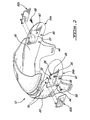
- Figure 1 is a perspective view of a helmet having an adjustment mechanism according to a particular embodiment of the present invention
- Figure 2 is a perspective exploded view of a front section and of levers of the helmet of Figure 1;
- Figure 3 is a side, partial view of the helmet of Figure 1, showing one of the levers in an unlocked position;
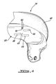
- Figure 4 is a side view of a rear section of the helmet of Figure 1;
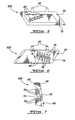
- Figure 5 is a front view of the lever of Figure 3;
- Figure 6 is a rear view of the lever of Figure 3.
- Figure 7 is a side view of the lever of Figure 3.
- the front and rear sections 12,14 are preferably formed of a high strength plastic material, composite material or a combination of two or more materials having an impact absorbing liner 16 disposed therein.
- the front and rear sections 12, 14 are interconnected through a pair of locking assemblies generally indicated at 18, only one of which being shown in Figure 1.
- the locking assemblies 18 are part of the adjustment mechanisms according to a particular embodiment of the present invention.
- the front section 12 has an inner surface 20 facing the head of a user and an opposed outer surface 22.
- the front section 12 also has two opposed side portions 24a,b, each including an elongated recess 26 defined in the outer surface 22.
- the recess 26 is shown here as having a parallelogram shape, it is understood that various other shapes are also possible, for example oblong, rectangular, triangular, etc.
- the recess 26 is defined by a recessed wall 28 substantially parallel to and inwardly offset from the outer surface 22, and connected thereto along its perimeter by a recessed border 30.
- the recessed wall 28 includes an elongated opening 32 defined therethrough configured and designed to be in communication with the inner surface 20.
- the opening 32 is formed by an elongated hole 34 from which extends a series of regularly spaced apart slots 36.
- the elongated hole 34 has a parallelogram shape defined by two parallel elongated sides 38 and two parallel short sides 40, the short sides 40 defining a width W h of the elongated hole 34.
- the spaced apart slots 36 extend substantially parallel to the short sides 40, with each slot 36 extending from one of the elongated sides 38 in alignment with a corresponding slot 36 extending from the other elongated side 38.
- the front section 12 also has first, second and third holes 42,44,46 defined in each of the side portions 24a,b.
- Each first hole 42 is defined through its respective recessed wall 28, while the second and third holes 44,46 are defined through the wall of the side portion 24a,b under the respective recess 26.
- the rear section 14 has an inner surface (not shown), an outer surface 48, and two side portions 50 (only one of which is shown).
- Each side portion 50 has first, second and third slots 52,54,56 defined therethrough.
- the slots 52,54,56 are substantially parallel to each other and spaced apart in a pattern corresponding to a pattern formed by the first, second and third holes 42,44,46 of the front section 12, such that each slot 52,54,56 is aligned with a corresponding one of the holes 42,44,46 when the front and rear sections 12,14 are engaged to form the helmet 10.
- the slots 52,54,56 have an oblong shape, although alternate shapes such as rectangular, polygonal, etc. are also possible.
- the holes 42,44,46 and slots 52,54,56 can be in a number of alternative locations and configurations, including having the slots 52,54,56 defined in the front section 12 and the holes 42,44,46 defined in the rear section 14 and/or having more or less holes 42,44,46 and slots 52,54,56.
- a plurality of screws 58 interconnect the front and rear sections 12,14, one screw 58 being inserted through each pair of corresponding hole and slot 42,52; 44,54; 46,56.
- the interconnected front and rear sections 12,14 are thus slidable with respect to one another through sliding of the screws 58 within the respective slot 52,54,56.
- the contact between the front and rear sections 12,14 is done through sliding surfaces 57,59 which are in sliding engagement with one another in a substantially interference-free manner.
- the sliding surfaces 57 of the front section 12 are defined by the inner surface 20 thereof within the side portions 24a,b (see Figure 2).
- the sliding surfaces 59 of the rear section 14 are defined by the outer surface 48 thereof within the side portions 50 (see Figure 4). Also, as the top portion of the rear section 14 overlaps the top portion of the front section 12 when the two are engaged to one another, the outer surface 22 of the front section 12 at that location slides against the inner surface (not shown) of the rear section 14, again without substantial interference.
- each side portion 50 of the rear section 14 includes two spaced apart arms 60 (see Figures 3-4) extending from the outer surface 48.
- the arms 60 have a width W a which is smaller than the width W h of the elongated hole 34 of the front section 12, and are located such as to extend therethrough when the front and rear sections 12,14 are slidably engaged.
- the arms 60 are slidable within the elongated hole 34 following the relative sliding motion of the front and rear sections 12,14.
- the arms 60 define a free space 61 therebetween which has substantially the same size than and can be substantially aligned with corresponding slots 36 of the opening 32.
- Each locking assembly 18 also includes a lever 62a,b.
- the lever 62b includes a body 64 shown here as having a parallelogram shape, although other shapes are also possible. In the embodiment shown, the body 64 is shaped such as to be receivable within the corresponding recess 26, as will be further detailed below.
- Two attachment arms 66 extend from the body 64, each arm 66 having a hole 68 defined therethrough (see Figure 7) with the two holes 68 being aligned with one another.
- the arms are receivable within corresponding indentations 70 defined in the front section 12 in proximity of the recess 26 (see Figure 2).
- a pin (not shown) is insertable through the aligned holes 68 and retained on the front section 12, thus attaching the lever 62b to the front section 12 in a pivotable manner.
- Other means of pivotably attaching levers 62a,b to the front section are possible, including through the use of a press-fit attachment, etc.
- the lever 62b is thus pivotable between a locked position, where the body 64 can be located within the recess 26 of the front section 12 (see Figure 1) and an unlocked position, where the body 64 can extend, for example, substantially perpendicular to the adjacent portion of the outer surface 22 of the front section 12 (see Figure 3).
- the recess 26 can be omitted and the lever 62b in the locked position lies against the outer surface 22 of the side portion 24.
- the body 64 defines an outer surface 72 upon which can be included a desired indicia, for example the helmet brand or a team logo.
- the body 64 also defines an inner surface 74 from which extend a plurality of spaced apart teeth 76, 78.
- the teeth 76,78 are distributed in a top row of teeth 76 and a bottom row of teeth 78, with each top tooth 76 being aligned with a corresponding bottom tooth 78.
- the two rows of aligned teeth 76,78 can be replaced by a single row of larger teeth.
- the teeth 76,78 are sized and positioned to be insertable in the slots 36 of the opening 32 of the front section 12 when the lever 62a,b is in the locked position, and as such are shown here as being distributed following a parallelogrammic pattern.
- the top and bottom teeth 76,78 thus together have a total width W t (see Figure 6) which is greater than the width W h (see Figure 3) of the elongated hole 34, the portion of the teeth 76,78 extending beyond the hole 34 being receivable within the slots 36.
- W t see Figure 6
- W h see Figure 3
- the body 64 is also shown as having a plurality of holes 80 defined therethrough between each pair of aligned bottom and top teeth 76,78, although such holes 80 can be alternately omitted.
- the helmet is formed by assembling the front and rear sections 12,14 (see Figure 1) by inserting and securing the screws 58 (see Figures 1-2) into each of the first, second and third slots 52,54,56 and corresponding one of the first, second and third holes 42,44,46.
- the size of the helmet 10 is adjusted with the levers 62a,b in the unlocked position shown in Figure 3.
- the front and rear sections 12,14 are thus free to slide with respect to one another, within a limit determined by the sliding motion of each screw 58 in its respective slot 52,54,56, and by the sliding motion of the arms 60 within the elongated hole 34.
- the front and rear sections 12,14 are moved to one of the positions where the free space 61 between the arms 60 is substantially continuous with one pair of aligned slots 36 of the opening 32. In the embodiment shown, seven (7) different positions are thus possible, i.e. one for each pair of aligned slots 36, although it is understood that more or less positions can be provided by varying the number of slots 36 or the number of arms 60.
- the levers 62a,b are pivoted to the locked position shown in Figure 1, where the teeth 76,78 are engaged in the elongated hole 34 and slots 36 of the opening 32 of the front section 12, and one pair of top and bottom teeth 76,78 is additionally engaged in the space 61 between the arms 60 extending from the rear section 14.
- a single tooth is engaged within the space 61.
- the engaged arms 60 and teeth 76,78 effectively block the relative sliding motion of the front and rear sections 12,14, thus locking the helmet 10 in the desired position and size.
- the adjustment can be accomplished while a user is wearing the helmet 10 or, if desired, while the helmet 10 is removed from the wearer's head.
- the levers 62a,b can advantageously be completely contained in the respective recess 26, and in a particular embodiment, disposed below the level of the outer surface 22 of the front section 12, and as such shielded from accidental or unwanted contact.
- the present device could be use in numerous other types of helmets or protection gear, and should not be viewed as limited to hockey or even to sports.
- the present invention may be used in relation to lacrosse, football, and other contact sports.
- the slots 36 could be omitted from the opening 32, and in this case the teeth 76,78 would be sized to fit within the elongated hole 34. More or less teeth 76,78 can be provided, as well as more than two arms 60.
Landscapes
- Helmets And Other Head Coverings (AREA)
Applications Claiming Priority (1)
| Application Number | Priority Date | Filing Date | Title |
|---|---|---|---|
| CA002533493A CA2533493C (fr) | 2006-01-20 | 2006-01-20 | Mecanisme de reglage pour casque |
Publications (2)
| Publication Number | Publication Date |
|---|---|
| EP1810583A1 true EP1810583A1 (fr) | 2007-07-25 |
| EP1810583B1 EP1810583B1 (fr) | 2010-01-13 |
Family
ID=37964301
Family Applications (1)
| Application Number | Title | Priority Date | Filing Date |
|---|---|---|---|
| EP07100921A Not-in-force EP1810583B1 (fr) | 2006-01-20 | 2007-01-22 | Mécanisme d'ajustement pour casque |
Country Status (4)
| Country | Link |
|---|---|
| EP (1) | EP1810583B1 (fr) |
| AT (1) | ATE454832T1 (fr) |
| CA (1) | CA2533493C (fr) |
| DE (1) | DE602007004248D1 (fr) |
Families Citing this family (4)
| Publication number | Priority date | Publication date | Assignee | Title |
|---|---|---|---|---|
| US9226539B2 (en) | 2010-07-13 | 2016-01-05 | Sport Maska Inc. | Helmet with rigid shell and adjustable liner |
| US10306941B2 (en) | 2011-07-27 | 2019-06-04 | Bauer Hockey, Llc | Sports helmet with rotational impact protection |
| US10477909B2 (en) | 2013-12-19 | 2019-11-19 | Bauer Hockey, Llc | Helmet for impact protection |
| US9961952B2 (en) | 2015-08-17 | 2018-05-08 | Bauer Hockey, Llc | Helmet for impact protection |
Citations (6)
| Publication number | Priority date | Publication date | Assignee | Title |
|---|---|---|---|---|
| US4539715A (en) * | 1983-04-22 | 1985-09-10 | Cooper Canada Limited | Size adjustable helmet |
| US5956776A (en) * | 1996-11-29 | 1999-09-28 | Bauer Inc. | Adjustable helmet having an improved locking mechanism |
| US6324700B1 (en) * | 1999-11-24 | 2001-12-04 | Bauer Nike Hockey Inc. | Adjustable protective helmet |
| US20040172739A1 (en) * | 2001-09-25 | 2004-09-09 | Bertrand Racine | Locking device for adjustable helmets |
| US20050015857A1 (en) * | 2003-07-21 | 2005-01-27 | Andre Desjardins | Adjustable helmet with disabling insert |
| WO2006005184A1 (fr) * | 2004-07-14 | 2006-01-19 | Sport Maska Inc. | Coque de casque ajustable |
-
2006
- 2006-01-20 CA CA002533493A patent/CA2533493C/fr not_active Expired - Lifetime
-
2007
- 2007-01-22 EP EP07100921A patent/EP1810583B1/fr not_active Not-in-force
- 2007-01-22 AT AT07100921T patent/ATE454832T1/de not_active IP Right Cessation
- 2007-01-22 DE DE602007004248T patent/DE602007004248D1/de not_active Expired - Fee Related
Patent Citations (6)
| Publication number | Priority date | Publication date | Assignee | Title |
|---|---|---|---|---|
| US4539715A (en) * | 1983-04-22 | 1985-09-10 | Cooper Canada Limited | Size adjustable helmet |
| US5956776A (en) * | 1996-11-29 | 1999-09-28 | Bauer Inc. | Adjustable helmet having an improved locking mechanism |
| US6324700B1 (en) * | 1999-11-24 | 2001-12-04 | Bauer Nike Hockey Inc. | Adjustable protective helmet |
| US20040172739A1 (en) * | 2001-09-25 | 2004-09-09 | Bertrand Racine | Locking device for adjustable helmets |
| US20050015857A1 (en) * | 2003-07-21 | 2005-01-27 | Andre Desjardins | Adjustable helmet with disabling insert |
| WO2006005184A1 (fr) * | 2004-07-14 | 2006-01-19 | Sport Maska Inc. | Coque de casque ajustable |
Also Published As
| Publication number | Publication date |
|---|---|
| CA2533493C (fr) | 2009-05-05 |
| CA2533493A1 (fr) | 2007-07-20 |
| ATE454832T1 (de) | 2010-01-15 |
| EP1810583B1 (fr) | 2010-01-13 |
| DE602007004248D1 (de) | 2010-03-04 |
Similar Documents
| Publication | Publication Date | Title |
|---|---|---|
| US7634820B2 (en) | Adjustment mechanism for a helmet | |
| US9526291B2 (en) | Helmet with rear adjustment mechanism | |
| US11375766B2 (en) | Adjustable helmet for a hockey or lacrosse player | |
| CA2561540C (fr) | Mecanisme d'ajustement pour casque | |
| CA2191693C (fr) | Casque ajustable avec mecanisme de verrouillage ameliore | |
| US8499366B2 (en) | Helmet with shell having raised central channel | |
| US10219576B2 (en) | Sport helmet | |
| US7043772B2 (en) | Ratchet mechanism with unitary knob and pinion construction | |
| RU2355268C2 (ru) | Оболочка регулируемого шлема | |
| EP1429635B1 (fr) | Casque de hockey reglable | |
| US20030182716A1 (en) | Helmet | |
| US20060156448A1 (en) | Adjustable stabilization strap apparatus | |
| EP1810583B1 (fr) | Mécanisme d'ajustement pour casque | |
| CA3144235C (fr) | Casque de sport reglable | |
| CA2820278C (fr) | Casque equipe d'un mecanisme d'ajustement arriere | |
| CA2843717C (fr) | Casque de sport ameliore | |
| EP3616544B1 (fr) | Écran de protection faciale pour casque de hockey | |
| WO2025118085A1 (fr) | Casque de protection doté d'un mécanisme de réglage | |
| US20130145526A1 (en) | Face mask with lens retaining assembly | |
| WO2024100522A1 (fr) | Dispositif de connexion |
Legal Events
| Date | Code | Title | Description |
|---|---|---|---|
| PUAI | Public reference made under article 153(3) epc to a published international application that has entered the european phase |
Free format text: ORIGINAL CODE: 0009012 |
|
| AK | Designated contracting states |
Kind code of ref document: A1 Designated state(s): AT BE BG CH CY CZ DE DK EE ES FI FR GB GR HU IE IS IT LI LT LU LV MC NL PL PT RO SE SI SK TR |
|
| AX | Request for extension of the european patent |
Extension state: AL BA HR MK YU |
|
| 17P | Request for examination filed |
Effective date: 20071217 |
|
| AKX | Designation fees paid |
Designated state(s): AT BE BG CH CY CZ DE DK EE ES FI FR GB GR HU IE IS IT LI LT LU LV MC NL PL PT RO SE SI SK TR |
|
| GRAP | Despatch of communication of intention to grant a patent |
Free format text: ORIGINAL CODE: EPIDOSNIGR1 |
|
| GRAS | Grant fee paid |
Free format text: ORIGINAL CODE: EPIDOSNIGR3 |
|
| GRAA | (expected) grant |
Free format text: ORIGINAL CODE: 0009210 |
|
| AK | Designated contracting states |
Kind code of ref document: B1 Designated state(s): AT BE BG CH CY CZ DE DK EE ES FI FR GB GR HU IE IS IT LI LT LU LV MC NL PL PT RO SE SI SK TR |
|
| REG | Reference to a national code |
Ref country code: GB Ref legal event code: FG4D |
|
| REG | Reference to a national code |
Ref country code: CH Ref legal event code: EP |
|
| REG | Reference to a national code |
Ref country code: IE Ref legal event code: FG4D |
|
| REG | Reference to a national code |
Ref country code: SE Ref legal event code: TRGR |
|
| REF | Corresponds to: |
Ref document number: 602007004248 Country of ref document: DE Date of ref document: 20100304 Kind code of ref document: P |
|
| REG | Reference to a national code |
Ref country code: NL Ref legal event code: VDEP Effective date: 20100113 |
|
| LTIE | Lt: invalidation of european patent or patent extension |
Effective date: 20100113 |
|
| PG25 | Lapsed in a contracting state [announced via postgrant information from national office to epo] |
Ref country code: AT Free format text: LAPSE BECAUSE OF FAILURE TO SUBMIT A TRANSLATION OF THE DESCRIPTION OR TO PAY THE FEE WITHIN THE PRESCRIBED TIME-LIMIT Effective date: 20100113 |
|
| PG25 | Lapsed in a contracting state [announced via postgrant information from national office to epo] |
Ref country code: ES Free format text: LAPSE BECAUSE OF FAILURE TO SUBMIT A TRANSLATION OF THE DESCRIPTION OR TO PAY THE FEE WITHIN THE PRESCRIBED TIME-LIMIT Effective date: 20100424 Ref country code: IS Free format text: LAPSE BECAUSE OF FAILURE TO SUBMIT A TRANSLATION OF THE DESCRIPTION OR TO PAY THE FEE WITHIN THE PRESCRIBED TIME-LIMIT Effective date: 20100513 Ref country code: NL Free format text: LAPSE BECAUSE OF FAILURE TO SUBMIT A TRANSLATION OF THE DESCRIPTION OR TO PAY THE FEE WITHIN THE PRESCRIBED TIME-LIMIT Effective date: 20100113 Ref country code: LT Free format text: LAPSE BECAUSE OF FAILURE TO SUBMIT A TRANSLATION OF THE DESCRIPTION OR TO PAY THE FEE WITHIN THE PRESCRIBED TIME-LIMIT Effective date: 20100113 |
|
| PG25 | Lapsed in a contracting state [announced via postgrant information from national office to epo] |
Ref country code: MC Free format text: LAPSE BECAUSE OF NON-PAYMENT OF DUE FEES Effective date: 20100131 Ref country code: PL Free format text: LAPSE BECAUSE OF FAILURE TO SUBMIT A TRANSLATION OF THE DESCRIPTION OR TO PAY THE FEE WITHIN THE PRESCRIBED TIME-LIMIT Effective date: 20100113 Ref country code: LV Free format text: LAPSE BECAUSE OF FAILURE TO SUBMIT A TRANSLATION OF THE DESCRIPTION OR TO PAY THE FEE WITHIN THE PRESCRIBED TIME-LIMIT Effective date: 20100113 Ref country code: SI Free format text: LAPSE BECAUSE OF FAILURE TO SUBMIT A TRANSLATION OF THE DESCRIPTION OR TO PAY THE FEE WITHIN THE PRESCRIBED TIME-LIMIT Effective date: 20100113 |
|
| PG25 | Lapsed in a contracting state [announced via postgrant information from national office to epo] |
Ref country code: RO Free format text: LAPSE BECAUSE OF FAILURE TO SUBMIT A TRANSLATION OF THE DESCRIPTION OR TO PAY THE FEE WITHIN THE PRESCRIBED TIME-LIMIT Effective date: 20100113 Ref country code: EE Free format text: LAPSE BECAUSE OF FAILURE TO SUBMIT A TRANSLATION OF THE DESCRIPTION OR TO PAY THE FEE WITHIN THE PRESCRIBED TIME-LIMIT Effective date: 20100113 Ref country code: CY Free format text: LAPSE BECAUSE OF FAILURE TO SUBMIT A TRANSLATION OF THE DESCRIPTION OR TO PAY THE FEE WITHIN THE PRESCRIBED TIME-LIMIT Effective date: 20100113 Ref country code: BE Free format text: LAPSE BECAUSE OF FAILURE TO SUBMIT A TRANSLATION OF THE DESCRIPTION OR TO PAY THE FEE WITHIN THE PRESCRIBED TIME-LIMIT Effective date: 20100113 |
|
| PLBE | No opposition filed within time limit |
Free format text: ORIGINAL CODE: 0009261 |
|
| STAA | Information on the status of an ep patent application or granted ep patent |
Free format text: STATUS: NO OPPOSITION FILED WITHIN TIME LIMIT |
|
| PG25 | Lapsed in a contracting state [announced via postgrant information from national office to epo] |
Ref country code: CZ Free format text: LAPSE BECAUSE OF FAILURE TO SUBMIT A TRANSLATION OF THE DESCRIPTION OR TO PAY THE FEE WITHIN THE PRESCRIBED TIME-LIMIT Effective date: 20100113 Ref country code: BG Free format text: LAPSE BECAUSE OF FAILURE TO SUBMIT A TRANSLATION OF THE DESCRIPTION OR TO PAY THE FEE WITHIN THE PRESCRIBED TIME-LIMIT Effective date: 20100413 Ref country code: SK Free format text: LAPSE BECAUSE OF FAILURE TO SUBMIT A TRANSLATION OF THE DESCRIPTION OR TO PAY THE FEE WITHIN THE PRESCRIBED TIME-LIMIT Effective date: 20100113 Ref country code: DE Free format text: LAPSE BECAUSE OF NON-PAYMENT OF DUE FEES Effective date: 20100803 |
|
| 26N | No opposition filed |
Effective date: 20101014 |
|
| PG25 | Lapsed in a contracting state [announced via postgrant information from national office to epo] |
Ref country code: DK Free format text: LAPSE BECAUSE OF FAILURE TO SUBMIT A TRANSLATION OF THE DESCRIPTION OR TO PAY THE FEE WITHIN THE PRESCRIBED TIME-LIMIT Effective date: 20100113 Ref country code: IE Free format text: LAPSE BECAUSE OF NON-PAYMENT OF DUE FEES Effective date: 20100122 |
|
| PG25 | Lapsed in a contracting state [announced via postgrant information from national office to epo] |
Ref country code: IT Free format text: LAPSE BECAUSE OF FAILURE TO SUBMIT A TRANSLATION OF THE DESCRIPTION OR TO PAY THE FEE WITHIN THE PRESCRIBED TIME-LIMIT Effective date: 20100113 |
|
| REG | Reference to a national code |
Ref country code: FR Ref legal event code: ST Effective date: 20110228 |
|
| PG25 | Lapsed in a contracting state [announced via postgrant information from national office to epo] |
Ref country code: FR Free format text: LAPSE BECAUSE OF NON-PAYMENT OF DUE FEES Effective date: 20100315 |
|
| REG | Reference to a national code |
Ref country code: CH Ref legal event code: PL |
|
| GBPC | Gb: european patent ceased through non-payment of renewal fee |
Effective date: 20110122 |
|
| PG25 | Lapsed in a contracting state [announced via postgrant information from national office to epo] |
Ref country code: LI Free format text: LAPSE BECAUSE OF NON-PAYMENT OF DUE FEES Effective date: 20110131 Ref country code: CH Free format text: LAPSE BECAUSE OF NON-PAYMENT OF DUE FEES Effective date: 20110131 |
|
| PG25 | Lapsed in a contracting state [announced via postgrant information from national office to epo] |
Ref country code: GB Free format text: LAPSE BECAUSE OF NON-PAYMENT OF DUE FEES Effective date: 20110122 |
|
| PG25 | Lapsed in a contracting state [announced via postgrant information from national office to epo] |
Ref country code: HU Free format text: LAPSE BECAUSE OF FAILURE TO SUBMIT A TRANSLATION OF THE DESCRIPTION OR TO PAY THE FEE WITHIN THE PRESCRIBED TIME-LIMIT Effective date: 20100714 Ref country code: LU Free format text: LAPSE BECAUSE OF NON-PAYMENT OF DUE FEES Effective date: 20100122 Ref country code: PT Free format text: LAPSE BECAUSE OF FAILURE TO SUBMIT A TRANSLATION OF THE DESCRIPTION OR TO PAY THE FEE WITHIN THE PRESCRIBED TIME-LIMIT Effective date: 20100613 |
|
| PG25 | Lapsed in a contracting state [announced via postgrant information from national office to epo] |
Ref country code: TR Free format text: LAPSE BECAUSE OF FAILURE TO SUBMIT A TRANSLATION OF THE DESCRIPTION OR TO PAY THE FEE WITHIN THE PRESCRIBED TIME-LIMIT Effective date: 20100113 |
|
| PG25 | Lapsed in a contracting state [announced via postgrant information from national office to epo] |
Ref country code: GR Free format text: LAPSE BECAUSE OF FAILURE TO SUBMIT A TRANSLATION OF THE DESCRIPTION OR TO PAY THE FEE WITHIN THE PRESCRIBED TIME-LIMIT Effective date: 20100113 |
|
| PGFP | Annual fee paid to national office [announced via postgrant information from national office to epo] |
Ref country code: SE Payment date: 20200121 Year of fee payment: 14 Ref country code: FI Payment date: 20200122 Year of fee payment: 14 |
|
| REG | Reference to a national code |
Ref country code: FI Ref legal event code: MAE |
|
| REG | Reference to a national code |
Ref country code: SE Ref legal event code: EUG |
|
| PG25 | Lapsed in a contracting state [announced via postgrant information from national office to epo] |
Ref country code: FI Free format text: LAPSE BECAUSE OF NON-PAYMENT OF DUE FEES Effective date: 20210122 |
|
| PG25 | Lapsed in a contracting state [announced via postgrant information from national office to epo] |
Ref country code: SE Free format text: LAPSE BECAUSE OF NON-PAYMENT OF DUE FEES Effective date: 20210123 |