EP1810585B1 - Vorrichtung zum Messen und Abformen des Fusses und zur Herstellung von Einlagen, Einlagesohlen oder Fussbetten - Google Patents
Vorrichtung zum Messen und Abformen des Fusses und zur Herstellung von Einlagen, Einlagesohlen oder Fussbetten Download PDFInfo
- Publication number
- EP1810585B1 EP1810585B1 EP07400001A EP07400001A EP1810585B1 EP 1810585 B1 EP1810585 B1 EP 1810585B1 EP 07400001 A EP07400001 A EP 07400001A EP 07400001 A EP07400001 A EP 07400001A EP 1810585 B1 EP1810585 B1 EP 1810585B1
- Authority
- EP
- European Patent Office
- Prior art keywords
- webs
- lugs
- outs
- cut
- base
- Prior art date
- Legal status (The legal status is an assumption and is not a legal conclusion. Google has not performed a legal analysis and makes no representation as to the accuracy of the status listed.)
- Active
Links
Images


Classifications
-
- A—HUMAN NECESSITIES
- A43—FOOTWEAR
- A43D—MACHINES, TOOLS, EQUIPMENT OR METHODS FOR MANUFACTURING OR REPAIRING FOOTWEAR
- A43D1/00—Foot or last measuring devices; Measuring devices for shoe parts
- A43D1/02—Foot-measuring devices
- A43D1/022—Foot-measuring devices involving making footprints or permanent moulds of the foot
Definitions
- the invention relates to a device for measuring and shaping the foot as a topographic footprint and for the production of insoles, insoles or footbeds and the like according to the preamble of claim 1.
- an existing plastic blank is dipped in boiling water and then formed directly by hand after the living foot.
- materials which are kneadable and deformable at relatively low temperatures are suitable for this method.
- such materials are extremely expensive in commerce.
- the insert is made after the plaster cast, on which the previously heated blank is applied. Subsequently, an air cushion press is pressed against the mass applied to the plaster positive. Since considerable rework is also required here, this method has not proven in practice. The disadvantage lies mainly in the poor contour sharpness of the molded insert.
- the surface formed by the upper pin ends represents a negative of the sole of the foot.
- the templates thus obtained are then placed in a device and scanned line by line in the XY plane by a probe. In synchronism with this movement, a milling device is moved line by line over a shoe insert blank.
- This known device has various disadvantages.
- the measuring template with its large number of pins and the clamping device is complicated. It is important that the pins run in the same direction and under the same spring pressure in order to obtain the same measuring conditions at all measuring points. Measuring errors are transmitted directly to the shoe insert because of the mechanical coupling to the milling device and must, as far as recognizable, be laboriously eliminated manually.
- the templates must be used in the fixed form in the manufacturing facility. Therefore, the measurement must be done in close proximity to the manufacturing facility to avoid the risk of altering the documents during transport.
- the invention requires the presence of a milling machine.
- WO 97/11619 an invention for the production of insoles is described in which the result of the measurement of the sole of the foot is obtained in a more easily transferable and processable form and after largely automated implementation of the control of a device for the production of shoe inserts is used.
- the measurement result is preferably delivered in electronic signals.
- the sole of the foot is scanned line by line by one or more sensors.
- the data supplied by the measuring device are converted into control data for the manufacturing device.
- the controller which is connected to the manufacturing device, the data are read.
- a file with the topographies of both feet is loaded into the controller via a data interface.
- the two blanks are processed on a rotatable rotary table by means of a hard metal grinding body.
- the manufacturing device works in a spiral.
- Data transmission system be available or purchased. The relatively high costs for this are also to be considered. Furthermore, the use of the invention requires errat trained personnel.
- the object of the invention is to provide a device by means of which in a simple and cost-effective manner orthopedic effects can be achieved by the production of shoe inserts and the like.
- the advantages achieved by the invention are, in particular, that the result of measuring the foot topography is obtained in a readily transferable and processable form and the insole, the footbed or the like can be produced cost-effectively with little effort in the same device in which the foot was measured.
- it is a device for measuring the foot topography with foot deformations and orthopedic peculiarities and for producing a shoe insert, footbed and the like corresponding to this topography.
- An applied grate simplifies the processing of the slats.
- An advantageous embodiment is a development that makes it possible to use the device for measuring the foot in horizontal (for length, width and width determination) and vertical (for toe and instep height and width determination) direction.
- Another possible embodiment of the subject invention is achieved as follows: By introducing measuring sensors in the web interstices of the fixed base, the depth of immersion of the respective slats of the insole blank can be detected electronically and the data thus obtained are passed to a data processing system.
- the main body consists of a solid base 1 with vertical webs 2, a heel device device 3, a frame 4 and a measuring device 5.
- 3a is on the webs 2 of the solid pad 1 of the body on a replaceable insole blank 6, which is deformable by pressure.
- the lamellae 7 on the underside of the blank 6 are easily fixed to the webs 2 on the upper side of the fixed base 1 of the device by toothing.
- the webs 2 on the upper side of the fixed base 1 are provided with horizontal grooves 9 (FIG. 3 d ), which allow to fix the insole blank 6 by gently pressing in an initial position and hold the insole blank 6 in any position.
- the lamellae 7 of the blank 6 are pressed according to the modelling in the web spaces of the solid pad 1.
- the horizontal grooves 9 on the webs 2 of the fixed base 1 prevent sliding back to the original state Withdrawal of the print ( Fig. 3c ). If the topography is to be changed for orthopedic reasons, this can be done by raising or lowering the corresponding lamellae 7 or by introducing correction bodies 14 into the intermediate spaces of the webs 2, lamellae, knobs or the like of the firm support 1 before loading the insole. Blanks 6 by setting up the foot. 8
- the insole blank 6 can now be separated, which for example either a band saw can be used, or the contours of the webs 2 are signed and after removal of the blank 6 standing on the sign slats 7 by means of knives, scissors, pliers o. ä. be separated.
- the resulting insert can be used immediately without finishing.
- the rust 10 ( Fig. 4a ) consists of a flat plate 10, which is perforated in a grid-shaped manner by recesses 11, so that an arrangement of webs 12, gratings o.ä. arises ( Fig. 4a ).
- the dimensions of the recesses 11 correspond to the dimensions of the slats 7 on the underside of the insole blank 6.
- the replaceable insole blank 6 On the grate with recesses11 is the replaceable insole blank 6.
- the fins 7 of the insole blank 6 are pressed into the recesses 11 of the grate 10 and into the web gaps of the fixed base 1.
- results after the load by the foot 8 an image of the topography of the underside of the foot.
- the topography is retained due to the fixation of the fins 7 on the underside of the blank 6 in the recesses 11 of the grate 10.
- the recesses 11 of the grate 10 are smaller by such that the foot corresponding insole blank 6 after pressing is fixed so strong with the foot 8 in the grid 10 that the shape of the insole blank 6 can be changed according to the desired correction of réelletopographie by processing the slats 7 on the underside of the insole blank 6.
- the processing of the slats 7 of the insole blank 6 can be done directly on the underside of the grate 10 ( Fig. 4e ). According to the orthopedic conditions, the slats 7 of the insole blank 6 are raised or lowered. After this Split off ( Fig. 4f ) of the lamellar projections 13 by means of a cutting device, the resulting deposit can be used immediately without finishing.
Landscapes
- Life Sciences & Earth Sciences (AREA)
- Biophysics (AREA)
- Footwear And Its Accessory, Manufacturing Method And Apparatuses (AREA)
Description
- Die Erfindung betrifft eine Vorrichtung zum Messen und Abformen des Fußes als topographischer Fußabdruck und zur Herstellung von Einlagen, Einlegesohlen oder Fußbetten und dergleichen nach dem Oberbegriff des Anspruchs 1.
- Zur Herstellung von orthopädischen Einlagen verwendet man Standardformen aus Aluminium, Holz und dergleichen, zwischen welche der Rohling der orthopädischen Einlage eingefügt wird. Anschließend werden Ober- und Unterteil der Form unter Druck gesetzt und auf diese Weise eine Standardeinlage geformt. Zur individuellen Anpassung dieser Standardform bedarf es erheblicher Nacharbeiten. Eine in allen Einzelheiten formgerechte Einlage herzustellen, ist so kaum möglich.
- Nach einer anderen bekannten Methode wird ein aus Kunststoff bestehender Rohling in kochendes Wasser getaucht und anschließend direkt von Hand nach dem lebenden Fuß geformt. Für diese Methode eignen sich jedoch nur Materialien, welche bei relativ niedrigen Temperaturen knet- und verformbar sind. Derartige Werkstoffe sind jedoch im Handel außerordentlich teuer.
- Bei einer weiteren bekannten Verfahrensweise wird die Einlage nach dem Gipsabdruck hergestellt, auf welchen der vorher erwärmte Rohling aufgebracht wird. Anschließend wird eine Luftkissenpresse gegen die auf das Gipspositiv aufgebrachte Masse gedrückt. Da auch hier erhebliche Nacharbeiten erforderlich sind, hat sich diese Methode in der Praxis nicht bewährt. Der Nachteil liegt vor allem in der mangelhaften Konturschärfe der abgeformten Einlage.
- Für die Herstellung von Schuheinlagen werden einerseits Vorrichtungen zum Ausmessen der Füße, insbesondere der Topographie der Fußsohle und andererseits Geräte zur Herstellung der Schuheinlagen gemäß der Messung, gegebenenfalls unter Einbezug von angestrebten Korrekturen, benötigt. Für eine rationelle Herstellung von Schuheinlagen ist es wünschenswert, Messverfahren und Herstellungsverfahren in unkomplizierter Weise in einer einzigen Vorrichtung aufeinander abzustimmen.
- Aus der
EP-A-0071386 ist ein Gerät bekannt, bei dem die Form der Fußsohle zunächst auf einer Messvorrichtung, die aus einer Vielzahl unter Federdruck stehender Stifte besteht, abgetastet wird. - Die Oberfläche, die durch die oberen Stiftenden gebildet wird, stellt ein Negativ der Fußsohle dar. Die so erhaltenen Vorlagen werden dann in ein Gerät eingesetzt und zeilenweise in der XY-Ebene von einem Fühler abgetastet. Im Gleichlauf mit dieser Bewegung wird eine Fräservorrichtung zeilenweise über einen Schuheinlagen-Rohling bewegt. Diese bekannte Vorrichtung weist verschiedene Nachteile auf. Die Messvorlage mit ihrer Vielzahl Stifte und der Klemmvorrichtung ist kompliziert. Es ist wichtig, dass die Stifte gleichgut laufen und unter gleichem Federdruck stehen, um an allen Messpunkten übereinstimmende Messbedingungen zu erhalten. Messfehler werden wegen der mechanischen Kopplung zur Fräsvorrichtung direkt auf die Schuheinlage übertragen und müssen, soweit erkennbar, aufwendig manuell beseitigt werden. Die Vorlagen müssen in der fixierten Form in die Herstellungseinrichtung eingesetzt werden. Daher muss der Messvorgang in räumlicher Nähe zur Herstellungseinrichtung erfolgen, um das Risiko einer Veränderung der Vorlagen während des Transports zu vermeiden.
- Die Herstellung durch zeilenweises Abfräsen birgt die Gefahr, dass das Rohmaterial jeweils am Ende einer Zeile ausbricht. Außerdem haben zeilenweise arbeitende Fräsmaschinen den Nachteil, dass bei qualitativ hochwertiger Bearbeitung das Fräsen nur in einer Vorschubrichtung erfolgt und nach jedem Fräsen einer Zeile zunächst ein leerer Rücklauf der Fräseinrichtung geschaltet werden muss.
- Schließlich setzt die Erfindung das Vorhandensein einer Fräsmaschine voraus.
- In
WO 97/11619 - Die Fußsohle wird zeilenweise durch ein oder mehrere Sensoren abgetastet. Mittels einer Datenverarbeitungsanlage werden die von der Messeinrichtung gelieferten Daten in Steuerdaten für die Herstellungsvorrichtung umgewandelt. Auf einer entsprechend ausgerüsteten Steuerung, die mit der Herstellungsvorrichtung verbunden ist, werden die Daten eingelesen. Ein File mit den Topographien beider Füße wird über eine Datenschnittstelle in die Steuerung geladen. In der Herstellungsvorrichtung werden die beiden Rohlinge auf einem drehbaren Rundtisch mittels eines Hartmetallschleifkörpers bearbeitet. Die Herstellungseinrichtung arbeitet spiralförmig.
- Der Nachteil dieser Vorrichtung besteht darin, dass auch hier bei der Datenübertragung aufgetretenen Fehler an die Herstellungseinrichtung weitergegeben werden und korrigiert werden müssen. Weiterhin müssen Messvorrichtung, Herstellungsvorrichtung und
- Datenübertragungsanlage vorhanden sein bzw. angeschafft werden. Die relativ hohen Kosten hierfür sind ebenfalls zu berücksichtigen. Weiterhin setzt der Einsatz der Erfindung erntsprechend geschultes Personal voraus.
- Durch die bisher genutzten Verfahren wird viel Geduld vom Patienten abverlangt (mehrere Besuche beim Orthopäden und beim Orthopädieschuhmacher). Die bisher verwendeten Verfahren sind sehr zeit- und kostenintensiv. Durch den Arbeitsaufwand und die finanzielle Belastung bei der Anschaffung aufwendiger Messgeräte und Herstellungsvorrichtungen entstehen den Krankenkassen hohe Kosten. Diese finanzielle Last hat der Patient in immer höherem Maß mitzutragen. Eine optimale Versorgung des Patienten wird aus diesen Gründen nicht gewährleistet. Oft erhält ein Patient nur 1 Paar Einlagen im Halbjahr, die er für alle von ihm getragenen Schuhe nutzen muss. Dies ist auch aus fußhygienischer Sicht nicht akzeptabel, da die Einlage die aufgenommene Menge an Flüssigkeit (Schweiß) nicht mehr abgeben kann, wenn die Einlage beispielsweise vom Straßenschuhwerk in den Hausschuh und wieder ins Straßenschuhwerk gelegt wird. Angebracht wären zumindest 2 Paar Einlagen für jeden Patienten, damit ein Wechsel erfolgen kann. Könnten nun die Kosten und der Aufwand für die Herstellung von Schuheinlagen erheblich gesenkt werden, könnte ein Teil dieser Ersparnis dem Patienten zugute kommen.
- Aus der Druckschrift
EP 0 285 989 ist eine Vorrichtung bekannt welche die Grundlage für den Oberbegriff des Anspruchs 1 bildet. - Aufgabe der Erfindung ist es, eine Vorrichtung aufzuzeigen, mittels derer in einfacher und kostengünstiger Weise orthopädische Wirkungen durch die Herstellung von Schuheinlagen und dergleichen erzielt werden können.
- Zur Lösung der Aufgabe führt eine Vorrichtung mit den Merkmalen des Patentanspruches 1.
- Die mit der Erfindung erzielten Vorteile bestehen insbesondere darin, dass das Ergebnis der Vermessung der Fußtopographie in einer leicht übertragbaren und verarbeitbaren Form anfällt und die Einlegesohle, das Fußbett oder ähnliches mit geringem Arbeitsaufwand kostensparend in der selben Vorrichtung hergestellt werden kann, in der auch der Fuß vermessen wurde. Erfindungsgemäß handelt es sich um eine Vorrichtung zum Vermessen der Fußtopographie mit Fußdeformationen und orthopädischen Besonderheiten und zur Herstellung einer dieser Topographie entsprechenden Schuheinlage, Fußbettes und dergleichen. Durch einen aufgelegten Rost wird die Bearbeitung der Lamellen vereinfacht.
- Durch das Einbringen von Korrekturkörpern in die Zwischenräume der Stege, Lamellen, Noppen oder ähnliches des Grundkörpers können Unregelmäßigkeiten in der Fußtopographie ausgeglichen werden.
- Eine vorteilhafte Ausgestaltung ist eine Weiterbildung, die es ermöglicht, die Vorrichtung zum Vermessen des Fußes in horizontaler (für Längen-, Breiten- und Weitenbestimmung) und vertikaler (für Zehen- und Risthöhe sowie Weitenbestimmung) Richtung zu nutzen.
- Eine weitere Gestaltungsmöglichkeit des Erfindungsgegenstandes wird folgendermaßen erreicht: Durch das Einbringen von Mess-Sensoren in die Stegzwischenräume der festen Unterlage kann die Eintauchtiefe der jeweiligen Lamellen des Einlegesohlen-Rohlings elektronisch erfasst und die so gewonnenen Daten an eine Datenverarbeitungsanlage geleitet werden.
- Ein Ausführungsbeispiel der Erfindung ist in den Zeichnungen schematisch dargestellt und wird im Folgenden näher beschrieben.
- Es zeigen
- Fig. 1a
- Ansicht der Vorrichtung bestehend aus fester Unterlage mit senkrecht zur horizontalen Ebene stehenden Stegen;
- Fig. 1b
- Ansicht der Vorrichtung bestehend aus fester Unterlage mit senkrecht zur horizontalen Ebene stehenden Stegen und Fersenanlage;
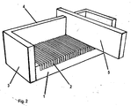
- Fig. 2
- Ansicht der Vorrichtung nach
Figur 1 mit Rahmen und Messvorrichtung ; - Fig. 3a
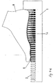
- seitliche Ansicht der Vorrichtung bestehend aus fester Unterlage mit senkrecht stehenden Stegen , Fersenanlage und Einlegesohlen-Rohling mit ebenfalls senkrechten Lamellen auf der Unterseite;
- Fig. 3b
- seitliche Ansicht der Vorrichtung nach
Figur 1 mit durch den Druck des Fußes ( belastetem Einlegesohlen-Rohling; - Fig. 3c
- seitliche Ansicht der Vorrichtung nach
Figur 1 nach erfolgter Druckbelastung durch den Fuß; - Fig. 3d
- schematische Vergrößerung der Stege auf der festen Unterlage mit horizontalen Längsrillen;
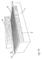
- Fig. 4a
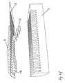
- Ansicht der Vorrichtung bestehend aus fester Unterlage mit senkrecht zur horizontalen Ebene stehenden Stegen , Rost mit Aussparungen und Stegen und Einlegesohlen-Rohling;
- Fig. 4b
- Ansicht der Vorrichtung bestehend aus fester Unterlage , auf den Grundkörper aufgelegten Rost und Einlegesohlen-Rohling;
- Fig. 4c
- seitliche Ansicht der Vorrichtung nach
Figur 4a und4b mit durch den Druck des Fußes belastetem Einlegesohlen-Rohling; - Fig. 4d
- seitliche Ansicht der Vorrichtung bestehend aus Grundkörper , mit durch den Druck der Fußes belastetem Einlegesohlenrohling und eingeschobenem Korrekturkörper;
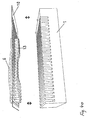
- Fig. 4e
- Ansicht der Vorrichtung bestehend aus Rost mit fixierter Einlegesohle und fester Unterlage;
- Fig. 4f
- seitliche Ansicht der Vorrichtung nach
Fig. 4e mit schematischer Darstellung der Abtrennung der nicht mehr benötigten Lamellenüberstände. - Der Grundkörper besteht aus einer festen Unterlage 1 mit senkrecht stehenden Stegen 2, einer Fersenanlagevorrichtung 3, einem Rahmen 4 und einer Messvorrichtung 5. Bei der Anwendung des Erfindungsgegenstandes (
Fig.3a ) liegt auf den Stegen 2 der festen Unterlage 1 des Grundkörpers ein austauschbarer Einlegesohlen-Rohling 6 auf, der durch Druck verformbar ist. Die Lamellen 7 an der Unterseite des Rohlings 6 sind dabei mit den Stegen 2 auf der Oberseite der festen Unterlage 1 des Gerätes durch Verzahnung leicht fixiert. Die Stege 2 auf der Oberseite der festen Unterlage 1 sind mit horizontalen Rillen 9 (Fig.3d ) versehen, die es erlauben, den Einlegesohlen-Rohling 6 durch leichtes Eindrücken in einer Anfangsstellung zu fixieren und den Einlegesohlen-Rohling 6 in jeder beliebigen Position halten. Nach erfolgter Belastung (Fig. 3b ) des Einlegesohlen-Rohlings 6 durch das Aufstellen des Fußes 8, sind die Lamellen 7 des Rohlings 6 entsprechend der Fußtopographie in die Stegzwischenräume der festen Unterlage 1 gepresst. Die Horizontal-Rillen 9 an den Stegen 2 der festen Unterlage 1 verhindern ein Zurückgleiten in den ursprünglichen Zustand nach Zurücknahme des Druckes (Fig. 3c ). Soll die Topographie aus orthopädischen Gründen geändert werden, kann dies durch Anheben bzw. Absenken der entsprechenden Lamellen 7 erfolgen oder durch das Einbringen von Korrekturkörpern 14 in die Zwischenräume der Stege 2, Lamellen, Noppen oder ähnliches der festen Unterlage 1 vor der Belastung des Einlegesohlen-Rohlings 6 durch das Aufstellen des Fußes 8. - Der Einlegesohlen-Rohling 6 kann nun abgetrennt werden, wobei hierfür zum Beispiel entweder eine Bandsäge verwendet werden kann, oder die Konturen der Stege 2 abgezeichnet werden und nach Entnahme des Rohlings 6 die über die Abzeichnung stehenden Lamellen 7 mittels Messer, Schere, Zange o.ä. abgetrennt werden. Die so entstandene Einlage kann sofort ohne Nachbearbeitung verwendet werden.
- Der Rost 10 (
Fig. 4a ) besteht aus einer flachen Platte 10, die rasterförmig durch Aussparungen 11 durchbrochen ist, sodass eine Anordnung von Stegen 12, Gittern o.ä. entsteht (Fig. 4a ). Die Abmessungen der Aussparungen11 entsprechen den Maßen der Lamellen 7 auf der Unterseite des Einlegesohlen-Rohlings 6. Bei kombinierter Nutzung von Grundkörper und Rost (Fig. 4c ) muss der Rost 10 in seinen Abmessungen der Unterlage 1 entsprechen. - Bei der kombinierten Anwendung liegt auf der Unterlage 1 der Rost 10 mit Aussparungen 11 auf (
Fig. 4b ). - Auf dem Rost mit Aussparungen11 liegt der austauschbare Einlegesohlen-Rohling 6. Entsprechend der Belastung mittels des natürlichen Fußes (
Fig. 4c ) sind die Lamellen 7 des Einlegesohlen-Rohlings 6 in die Aussparungen 11 des Rosts 10 und in die Stegzwischenräume der festen Unterlage 1 gedrückt. Wie oben beschrieben, ergibt sich nach erfolgter Belastung durch den Fuß 8 ein Abbild der Topographie der Fußunterseite. Nachdem der Rost 10 mit dem Einlegesohlen-Rohling 6 von der Unterlage 1 genommen wurde (Fig. 4e ), bleibt die Topographie erhalten infolge der Fixierung der Lamellen 7 auf der Unterseite des Rohlings 6 in den Aussparungen 11 des Rosts 10. Die Aussparungen 11 des Rosts 10 sind um ein solches kleiner, dass der dem Fuß entsprechend Einlegesohlen-Rohling 6 nach dem Einpressen mit dem Fuß 8 in den Rost 10 so stark fixiert ist, dass die Form des Einlegesohlen-Rohlings 6 entsprechend der gewünschten Korrektur der Fußtopographie durch Bearbeitung der Lamellen 7 auf der Unterseite der Einlegesohlen-Rohlings 6 geändert werden kann. Die Bearbeitung der Lamellen 7 des Einlegesohlen-Rohlings 6 kann direkt an der Unterseite des Rosts 10 erfolgen (Fig. 4e ). Entsprechend den orthopädischen Gegebenheiten werden die Lamellen 7 des Einlegesohlen-Rohlings6 angehoben oder abgesenkt. Nach dem Abtrennen (Fig. 4f ) der Lamellenüberstände 13 mittels eines Schneidgerätes kann die so entstandene Einlage sofort ohne Nachbearbeitung verwendet werden.
Claims (18)
- Vorrichtung zur Erfassung der Topographie eines Fußes und zur Herstellung eines Fußbettes, einer Einlage und dergleichen für Schuhe, dadurch gekennzeichnet, dass eine Anzahl Stege (2), Lamellen, Noppen, Aussparungen oder ähnliches auf einer festen Unterlage (1) oder Aussparungen (11) in einer rasterförmig durchbrochenen flachen Platte eines Rostes (10) angeordnet ist, auf welcher Unterlage (1) oder auf welchem Rost (10) ein austauschbarer Einlegesohlen-Rohling (6) mit unterseitigen Lamellen (7), Noppen oder ähnlichem aufliegt, wobei die Lamellen (7), Noppen oder ähnliches mittels Belastung durch den Fuß (8) zur Erfassung der Fußtopographie entsprechend der Form der Fußsohle in die Zwischenräume der Stege (2), Lamellen, Noppen Aussparungen oder ähnliches der Unterlage (1) oder mehr oder minder tief durch die Aussparungen (11) des Rostes (10) gedrückt werden.
- Vorrichtung nach Anspruch 1, dadurch gekennzeichnet, dass die Stege (2), Noppen, Aussparungen oder ähnliches senkrecht zur horizontalen Ebene der festen Unterlage (1) stehen.
- Vorrichtung nach Anspruch 1, dadurch gekennzeichnet, dass die Stege (2), Noppen, Aussparungen oder ähnliches in Längs- oder Querrichtung oder schräg in der horizontalen Ebene angeordnet sind.
- Vorrichtung nach einem der Ansprüche 1 bis 3, dadurch gekennzeichnet, dass die Stege (2), Noppen oder ähnliches fest auf der Unterlage (1) positioniert sind.
- Vorrichtung gemäß Anspruch 1, dadurch gekennzeichnet, dass die Stege (2), Noppen oder ähnliches auf der Unterlage (1) austauschbar sind.
- Vorrichtung nach Anspruch 5, dadurch gekennzeichnet, dass die Stege (2), Noppen oder ähnliches mittels Stiften auf der festen Unterlage (1) positioniert sind, wobei die Positionierungsstifte in einer oder mehreren Reihen angeordnet sind oder die Fläche der Unterlage (1) vollkommen willkürlich teilweise oder ganz bedecken.
- Vorrichtung nach einem der Ansprüche 1 bis 6, dadurch gekennzeichnet, dass die feste Unterlage (1) in einem Rahmen (4) liegt.
- Vorrichtung nach Anspruch 1, dadurch gekennzeichnet, dass sie eine Messvorrichtung (5) zur Bestimmung der Fußmaße enthält, wobei sich an einer Schmalseite der Unterlage (1) eine Fersenanlage (3) befindet.
- Vorrichtung nach Anspruch 1, dadurch gekennzeichnet, dass die Abstände zwischen den Stegen (2), Lamellen, Noppen, Aussparungen oder ähnlichem der festen Unterlage (1) oder die Aussparungen (11) des Rostes (10) um ein solches kleiner sind, dass der dem Fuß entsprechende Einlegesohlen-Rohling (6) nach dem Einpressen mit dem Fuß (8) in die Unterlage (1) oder in den Rost (10) so stark fixiert ist, dass die Form des Einlegesohlen-Rohlings (6) entsprechend der gewünschten Korrektur der Fußtopographie verändert werden kann.
- Vorrichtung nach einem der Ansprüche 1 bis 6, dadurch gekennzeichnet, dass die Stege (2), Noppen, Aussparungen oder ähnliches der festen Unterlage (1) zur Fixierung des Einlegesohlen-Rohlings (6) mit Horizontal-Rillen (9), Haftmasse oder ähnlichem versehen sind.
- Vorrichtung nach Anspruch 1, dadurch gekennzeichnet, dass sich zwischen den Stegen (2), Noppen, Aussparungen oder ähnlichem der festen Unterlage (1) Mess-Sensoren befinden, um die Eintauchtiefe der jeweiligen Lamellen (7) des Einlegesohlen-Rohlings (6) zur elektronischen Erfassung zu bestimmen.
- Vorrichtung nach Anspruch 1, dadurch gekennzeichnet, dass zwischen den Stegen (2), Noppen, Lamellen, Aussparungen oder ähnlichem der Unterlage (1) Korrekturkörper (14) liegen, um Unregelmäßigkeiten in der Fußtopographie auszugleichen.
- Vorrichtung nach Anspruch 1, dadurch gekennzeichnet, dass das Muster der Aussparungen (11) des Rostes (10) in Anordnung und Form den Lamellen (7), Stegen, Noppen oder ähnlichem auf der Unterseite des Einlegesohlen-Rohlings (6) entspricht.
- Vorrichtung nach Anspruch 1, dadurch gekennzeichnet, dass sie eine Unterlage (1) und einen Rost (10) umfasst und der Rost (10) auf der Unterlage (1) aufliegt.
- Vorrichtung nach Anspruch 14, dadurch gekennzeichnet, dass die Abmessungen der Aussparungen (11) des Rostes (10) in Anordnung, Form und Maßen den Stegen (2), Lamellen, Noppen, Aussparungen und dergleichen auf der festen Unterlage (1) entsprechen.
- Vorrichtung nach Anspruch 14 oder 15, dadurch gekennzeichnet, dass die Lamellen (7) des Einlegesohlen-Rohlings (6) durch einen zweiten Rost, der dem ersten untergelagert ist, fixiert sind.
- Vorrichtung nach einem der Ansprüche 14 bis 16, dadurch gekennzeichnet, dass die Stege (12) des Rostes (10) nach unten versenkbar sind.
- Vorrichtung nach einem der Ansprüche 14 bis 16, dadurch gekennzeichnet, dass die Stege (12) des Rostes (10) zur Seite verschiebbar sind.
Priority Applications (1)
| Application Number | Priority Date | Filing Date | Title |
|---|---|---|---|
| PL07400001T PL1810585T3 (pl) | 2006-01-24 | 2007-01-09 | Przyrząd do pomiaru topografii stopy oraz wytwarzania wkładek albo wyściółek |
Applications Claiming Priority (2)
| Application Number | Priority Date | Filing Date | Title |
|---|---|---|---|
| DE200620001178 DE202006001178U1 (de) | 2006-01-24 | 2006-01-24 | Vorrichtung zum Messen und Abformen des Fusses und zur Herstellung von Einlagen, Einlegesohlen oder Fußbetten |
| DE200610003553 DE102006003553A1 (de) | 2006-01-24 | 2006-01-24 | Vorrichtung zum Messen und Abformen des Fußes und zur Herstellung von Einlagen, Einlegesohlen oder Fußbetten |
Publications (3)
| Publication Number | Publication Date |
|---|---|
| EP1810585A2 EP1810585A2 (de) | 2007-07-25 |
| EP1810585A3 EP1810585A3 (de) | 2007-12-05 |
| EP1810585B1 true EP1810585B1 (de) | 2009-05-06 |
Family
ID=38057348
Family Applications (1)
| Application Number | Title | Priority Date | Filing Date |
|---|---|---|---|
| EP07400001A Active EP1810585B1 (de) | 2006-01-24 | 2007-01-09 | Vorrichtung zum Messen und Abformen des Fusses und zur Herstellung von Einlagen, Einlagesohlen oder Fussbetten |
Country Status (6)
| Country | Link |
|---|---|
| EP (1) | EP1810585B1 (de) |
| AT (1) | ATE430499T1 (de) |
| DE (1) | DE502007000677D1 (de) |
| DK (1) | DK1810585T3 (de) |
| ES (1) | ES2327074T3 (de) |
| PL (1) | PL1810585T3 (de) |
Families Citing this family (1)
| Publication number | Priority date | Publication date | Assignee | Title |
|---|---|---|---|---|
| CN107874762B (zh) * | 2017-12-25 | 2023-07-21 | 苏州半鱼健康科技服务有限公司 | 一种脚底形状采集装置 |
Family Cites Families (4)
| Publication number | Priority date | Publication date | Assignee | Title |
|---|---|---|---|---|
| EP0071386A3 (de) | 1981-07-23 | 1983-08-03 | Amfit Inc. | System und Verfahren zur Herstellung von nach Mass angefertigten Schuhen und Schuheinlagen dafür |
| JPH0751084B2 (ja) * | 1987-04-06 | 1995-06-05 | 和豊 鈴木 | 足型の採取装置 |
| AU718646B2 (en) | 1995-09-27 | 2000-04-20 | Hans-Rudolf Rickli | Installation for the manufacture of shoe inserts |
| DE202006001178U1 (de) * | 2006-01-24 | 2006-11-09 | Hundertmarck, Günter | Vorrichtung zum Messen und Abformen des Fusses und zur Herstellung von Einlagen, Einlegesohlen oder Fußbetten |
-
2007
- 2007-01-09 DE DE502007000677T patent/DE502007000677D1/de active Active
- 2007-01-09 AT AT07400001T patent/ATE430499T1/de active
- 2007-01-09 DK DK07400001T patent/DK1810585T3/da active
- 2007-01-09 PL PL07400001T patent/PL1810585T3/pl unknown
- 2007-01-09 ES ES07400001T patent/ES2327074T3/es active Active
- 2007-01-09 EP EP07400001A patent/EP1810585B1/de active Active
Also Published As
| Publication number | Publication date |
|---|---|
| EP1810585A3 (de) | 2007-12-05 |
| EP1810585A2 (de) | 2007-07-25 |
| DK1810585T3 (da) | 2009-08-31 |
| DE502007000677D1 (de) | 2009-06-18 |
| ATE430499T1 (de) | 2009-05-15 |
| ES2327074T3 (es) | 2009-10-23 |
| PL1810585T3 (pl) | 2009-10-30 |
Similar Documents
| Publication | Publication Date | Title |
|---|---|---|
| WO1988009147A1 (fr) | Procede et dispositif pour la fabrication de garnitures ou similaire | |
| WO2007112766A1 (de) | Verfahren und vorrichtung zur herstellung eines entsprechend einer anatomischen sollform vorgeformten flächigen implantats für einen menschlichen oder tierischen körper | |
| DE102011120789B4 (de) | Verfahren zur Endbearbeitung eines Platinen-Umformwerkzeuges | |
| EP1810585B1 (de) | Vorrichtung zum Messen und Abformen des Fusses und zur Herstellung von Einlagen, Einlagesohlen oder Fussbetten | |
| EP3045152A1 (de) | Haltevorrichtung für die herstellung einer orthese sowie vorrichtung und verfahren zur herstellung einer orthese | |
| DE102011055238B4 (de) | Verfahren zur Herstellung einer Schuheinlage | |
| DE102004022158B4 (de) | Vorrichtung und ein Baukastensystem für die Herstellung orthopädischer Schuh- und/oder Einbaueinlagen sowie orthopädische Schuh- und/oder Einbaueinlage als solche | |
| DE2320196C3 (de) | Verfahren zur Herstellung eines gewölbten, langgestreckten Sportgerätes, z.B. Ski oder Bogen, sowie zur Durchfuhrung des Verfahrens verwendete Form | |
| DE202006001178U1 (de) | Vorrichtung zum Messen und Abformen des Fusses und zur Herstellung von Einlagen, Einlegesohlen oder Fußbetten | |
| DE102006003553A1 (de) | Vorrichtung zum Messen und Abformen des Fußes und zur Herstellung von Einlagen, Einlegesohlen oder Fußbetten | |
| DE1441362A1 (de) | Als Fussstuetze dienende Schuheinlage aus thermoplastischem Werkstoff sowie Verfahren und Vorrichtung zum Herstellen dieser Schuheinlage | |
| DE10346531B4 (de) | Verfahren und Vorrichtung zum Anpassen einer Fußstützvorrichtung | |
| DE102019126598B3 (de) | Orthopädisches Fußsohlen-Scansystem, Verfahren zum Ermitteln einer dreidimensionalen Form einer Schuheinlage und Verfahren zum automatischen Herstellen einer Schuheinlage | |
| EP4061293B1 (de) | Verfahren zum erstellen eines 3 d-scans | |
| DE102014001508B4 (de) | Vorrichtung zum Herstellen eines Schutzes für einen Huf | |
| DE1077569B (de) | Verfahren und Vorrichtung zum Abformen orthopaedisch korrigierter Fuesse in belastetem Zustand | |
| DE2317362A1 (de) | Lehrenvorrichtung fuer funkenerosionsmaschinen | |
| DE2213768B2 (de) | Verfahren und Vorrichtung zum ortsgenauen Einsetzen eines Schneidorganes zur Herstellung eines Gravierstichels für elektronische Druckform-Graviermaschinen | |
| DE817703C (de) | Geraet zum Zeichnen von Grundmustern, Leistenkopien | |
| DE10312129A1 (de) | Verfahren zur Herstellung von orthopädischen Maßschuhen | |
| DE102023112614B3 (de) | Verfahren zur automatisierten Anpassung eines Fußwerks an eine Fußanatomie | |
| DE102015102004B4 (de) | Stanzvorrichtung zum Ausstanzen von Teigstücken | |
| DE102023102474A1 (de) | Halbzeug, Schablonenteil, Schuheinlage, Vorrichtung und Verfahren zum Fertigen eines solchen Halbzeugs, sowie Verwendung eines Körpers eines Schablonenteils | |
| DE9400979U1 (de) | Bausatz zum Fertigen therapeutischer orthopädischer Einlagen | |
| DE660168C (de) | Vorrichtung zum Abnehmen der Abdruecke der Fusssohlenflaechen |
Legal Events
| Date | Code | Title | Description |
|---|---|---|---|
| PUAI | Public reference made under article 153(3) epc to a published international application that has entered the european phase |
Free format text: ORIGINAL CODE: 0009012 |
|
| AK | Designated contracting states |
Kind code of ref document: A2 Designated state(s): AT BE BG CH CY CZ DE DK EE ES FI FR GB GR HU IE IS IT LI LT LU LV MC NL PL PT RO SE SI SK TR |
|
| AX | Request for extension of the european patent |
Extension state: AL BA HR MK YU |
|
| PUAL | Search report despatched |
Free format text: ORIGINAL CODE: 0009013 |
|
| AK | Designated contracting states |
Kind code of ref document: A3 Designated state(s): AT BE BG CH CY CZ DE DK EE ES FI FR GB GR HU IE IS IT LI LT LU LV MC NL PL PT RO SE SI SK TR |
|
| AX | Request for extension of the european patent |
Extension state: AL BA HR MK YU |
|
| 17P | Request for examination filed |
Effective date: 20080322 |
|
| AKX | Designation fees paid |
Designated state(s): AT BE BG CH CY CZ DE DK EE ES FI FR GB GR HU IE IS IT LI LT LU LV MC NL PL PT RO SE SI SK TR |
|
| GRAP | Despatch of communication of intention to grant a patent |
Free format text: ORIGINAL CODE: EPIDOSNIGR1 |
|
| GRAS | Grant fee paid |
Free format text: ORIGINAL CODE: EPIDOSNIGR3 |
|
| GRAA | (expected) grant |
Free format text: ORIGINAL CODE: 0009210 |
|
| AK | Designated contracting states |
Kind code of ref document: B1 Designated state(s): AT BE BG CH CY CZ DE DK EE ES FI FR GB GR HU IE IS IT LI LT LU LV MC NL PL PT RO SE SI SK TR |
|
| REG | Reference to a national code |
Ref country code: GB Ref legal event code: FG4D Free format text: NOT ENGLISH |
|
| REG | Reference to a national code |
Ref country code: CH Ref legal event code: EP |
|
| REG | Reference to a national code |
Ref country code: IE Ref legal event code: FG4D |
|
| REF | Corresponds to: |
Ref document number: 502007000677 Country of ref document: DE Date of ref document: 20090618 Kind code of ref document: P |
|
| REG | Reference to a national code |
Ref country code: CH Ref legal event code: NV Representative=s name: ISLER & PEDRAZZINI AG |
|
| REG | Reference to a national code |
Ref country code: SE Ref legal event code: TRGR |
|
| REG | Reference to a national code |
Ref country code: DK Ref legal event code: T3 |
|
| REG | Reference to a national code |
Ref country code: GR Ref legal event code: EP Ref document number: 20090401980 Country of ref document: GR |
|
| REG | Reference to a national code |
Ref country code: ES Ref legal event code: FG2A Ref document number: 2327074 Country of ref document: ES Kind code of ref document: T3 |
|
| PG25 | Lapsed in a contracting state [announced via postgrant information from national office to epo] |
Ref country code: LT Free format text: LAPSE BECAUSE OF FAILURE TO SUBMIT A TRANSLATION OF THE DESCRIPTION OR TO PAY THE FEE WITHIN THE PRESCRIBED TIME-LIMIT Effective date: 20090506 |
|
| REG | Reference to a national code |
Ref country code: PL Ref legal event code: T3 |
|
| PG25 | Lapsed in a contracting state [announced via postgrant information from national office to epo] |
Ref country code: IS Free format text: LAPSE BECAUSE OF FAILURE TO SUBMIT A TRANSLATION OF THE DESCRIPTION OR TO PAY THE FEE WITHIN THE PRESCRIBED TIME-LIMIT Effective date: 20090906 Ref country code: LV Free format text: LAPSE BECAUSE OF FAILURE TO SUBMIT A TRANSLATION OF THE DESCRIPTION OR TO PAY THE FEE WITHIN THE PRESCRIBED TIME-LIMIT Effective date: 20090506 Ref country code: SI Free format text: LAPSE BECAUSE OF FAILURE TO SUBMIT A TRANSLATION OF THE DESCRIPTION OR TO PAY THE FEE WITHIN THE PRESCRIBED TIME-LIMIT Effective date: 20090506 |
|
| REG | Reference to a national code |
Ref country code: HU Ref legal event code: AG4A Ref document number: E006255 Country of ref document: HU |
|
| PG25 | Lapsed in a contracting state [announced via postgrant information from national office to epo] |
Ref country code: EE Free format text: LAPSE BECAUSE OF FAILURE TO SUBMIT A TRANSLATION OF THE DESCRIPTION OR TO PAY THE FEE WITHIN THE PRESCRIBED TIME-LIMIT Effective date: 20090506 Ref country code: RO Free format text: LAPSE BECAUSE OF FAILURE TO SUBMIT A TRANSLATION OF THE DESCRIPTION OR TO PAY THE FEE WITHIN THE PRESCRIBED TIME-LIMIT Effective date: 20090506 |
|
| PG25 | Lapsed in a contracting state [announced via postgrant information from national office to epo] |
Ref country code: SK Free format text: LAPSE BECAUSE OF FAILURE TO SUBMIT A TRANSLATION OF THE DESCRIPTION OR TO PAY THE FEE WITHIN THE PRESCRIBED TIME-LIMIT Effective date: 20090506 |
|
| PLBE | No opposition filed within time limit |
Free format text: ORIGINAL CODE: 0009261 |
|
| STAA | Information on the status of an ep patent application or granted ep patent |
Free format text: STATUS: NO OPPOSITION FILED WITHIN TIME LIMIT |
|
| PG25 | Lapsed in a contracting state [announced via postgrant information from national office to epo] |
Ref country code: BG Free format text: LAPSE BECAUSE OF FAILURE TO SUBMIT A TRANSLATION OF THE DESCRIPTION OR TO PAY THE FEE WITHIN THE PRESCRIBED TIME-LIMIT Effective date: 20090806 |
|
| 26N | No opposition filed |
Effective date: 20100209 |
|
| PG25 | Lapsed in a contracting state [announced via postgrant information from national office to epo] |
Ref country code: MC Free format text: LAPSE BECAUSE OF NON-PAYMENT OF DUE FEES Effective date: 20100131 |
|
| PGRI | Patent reinstated in contracting state [announced from national office to epo] |
Ref country code: IT Effective date: 20110501 |
|
| PG25 | Lapsed in a contracting state [announced via postgrant information from national office to epo] |
Ref country code: CY Free format text: LAPSE BECAUSE OF FAILURE TO SUBMIT A TRANSLATION OF THE DESCRIPTION OR TO PAY THE FEE WITHIN THE PRESCRIBED TIME-LIMIT Effective date: 20090506 |
|
| PG25 | Lapsed in a contracting state [announced via postgrant information from national office to epo] |
Ref country code: PT Free format text: LAPSE BECAUSE OF FAILURE TO SUBMIT A TRANSLATION OF THE DESCRIPTION OR TO PAY THE FEE WITHIN THE PRESCRIBED TIME-LIMIT Effective date: 20091006 |
|
| PG25 | Lapsed in a contracting state [announced via postgrant information from national office to epo] |
Ref country code: TR Free format text: LAPSE BECAUSE OF FAILURE TO SUBMIT A TRANSLATION OF THE DESCRIPTION OR TO PAY THE FEE WITHIN THE PRESCRIBED TIME-LIMIT Effective date: 20090506 |
|
| REG | Reference to a national code |
Ref country code: FR Ref legal event code: PLFP Year of fee payment: 9 |
|
| REG | Reference to a national code |
Ref country code: FR Ref legal event code: PLFP Year of fee payment: 10 |
|
| REG | Reference to a national code |
Ref country code: FR Ref legal event code: PLFP Year of fee payment: 11 |
|
| PGFP | Annual fee paid to national office [announced via postgrant information from national office to epo] |
Ref country code: CZ Payment date: 20161223 Year of fee payment: 11 |
|
| PGFP | Annual fee paid to national office [announced via postgrant information from national office to epo] |
Ref country code: GR Payment date: 20170116 Year of fee payment: 11 |
|
| PGFP | Annual fee paid to national office [announced via postgrant information from national office to epo] |
Ref country code: LU Payment date: 20170123 Year of fee payment: 11 Ref country code: DK Payment date: 20170119 Year of fee payment: 11 Ref country code: HU Payment date: 20170117 Year of fee payment: 11 |
|
| REG | Reference to a national code |
Ref country code: FR Ref legal event code: PLFP Year of fee payment: 12 |
|
| REG | Reference to a national code |
Ref country code: DK Ref legal event code: EBP Effective date: 20180131 |
|
| PG25 | Lapsed in a contracting state [announced via postgrant information from national office to epo] |
Ref country code: HU Free format text: LAPSE BECAUSE OF NON-PAYMENT OF DUE FEES Effective date: 20180110 Ref country code: LU Free format text: LAPSE BECAUSE OF NON-PAYMENT OF DUE FEES Effective date: 20180109 |
|
| PG25 | Lapsed in a contracting state [announced via postgrant information from national office to epo] |
Ref country code: GR Free format text: LAPSE BECAUSE OF NON-PAYMENT OF DUE FEES Effective date: 20180802 Ref country code: CZ Free format text: LAPSE BECAUSE OF NON-PAYMENT OF DUE FEES Effective date: 20180109 |
|
| PG25 | Lapsed in a contracting state [announced via postgrant information from national office to epo] |
Ref country code: DK Free format text: LAPSE BECAUSE OF NON-PAYMENT OF DUE FEES Effective date: 20180131 |
|
| PGFP | Annual fee paid to national office [announced via postgrant information from national office to epo] |
Ref country code: ES Payment date: 20190226 Year of fee payment: 13 |
|
| REG | Reference to a national code |
Ref country code: FI Ref legal event code: MAE |
|
| REG | Reference to a national code |
Ref country code: SE Ref legal event code: EUG |
|
| GBPC | Gb: european patent ceased through non-payment of renewal fee |
Effective date: 20200109 |
|
| REG | Reference to a national code |
Ref country code: SE Ref legal event code: EUG |
|
| PG25 | Lapsed in a contracting state [announced via postgrant information from national office to epo] |
Ref country code: SE Free format text: LAPSE BECAUSE OF NON-PAYMENT OF DUE FEES Effective date: 20200110 Ref country code: GB Free format text: LAPSE BECAUSE OF NON-PAYMENT OF DUE FEES Effective date: 20200109 Ref country code: FI Free format text: LAPSE BECAUSE OF NON-PAYMENT OF DUE FEES Effective date: 20200109 |
|
| PG25 | Lapsed in a contracting state [announced via postgrant information from national office to epo] |
Ref country code: IE Free format text: LAPSE BECAUSE OF NON-PAYMENT OF DUE FEES Effective date: 20200109 |
|
| PGFP | Annual fee paid to national office [announced via postgrant information from national office to epo] |
Ref country code: NL Payment date: 20210201 Year of fee payment: 15 |
|
| PGFP | Annual fee paid to national office [announced via postgrant information from national office to epo] |
Ref country code: BE Payment date: 20210201 Year of fee payment: 15 Ref country code: AT Payment date: 20210202 Year of fee payment: 15 |
|
| REG | Reference to a national code |
Ref country code: ES Ref legal event code: FD2A Effective date: 20210602 |
|
| PG25 | Lapsed in a contracting state [announced via postgrant information from national office to epo] |
Ref country code: ES Free format text: LAPSE BECAUSE OF NON-PAYMENT OF DUE FEES Effective date: 20200110 |
|
| REG | Reference to a national code |
Ref country code: NL Ref legal event code: MM Effective date: 20220201 |
|
| REG | Reference to a national code |
Ref country code: AT Ref legal event code: MM01 Ref document number: 430499 Country of ref document: AT Kind code of ref document: T Effective date: 20220109 |
|
| REG | Reference to a national code |
Ref country code: BE Ref legal event code: MM Effective date: 20220131 |
|
| PG25 | Lapsed in a contracting state [announced via postgrant information from national office to epo] |
Ref country code: NL Free format text: LAPSE BECAUSE OF NON-PAYMENT OF DUE FEES Effective date: 20220201 Ref country code: AT Free format text: LAPSE BECAUSE OF NON-PAYMENT OF DUE FEES Effective date: 20220109 |
|
| PG25 | Lapsed in a contracting state [announced via postgrant information from national office to epo] |
Ref country code: BE Free format text: LAPSE BECAUSE OF NON-PAYMENT OF DUE FEES Effective date: 20220131 |
|
| PGFP | Annual fee paid to national office [announced via postgrant information from national office to epo] |
Ref country code: PL Payment date: 20230105 Year of fee payment: 17 |
|
| PGFP | Annual fee paid to national office [announced via postgrant information from national office to epo] |
Ref country code: CH Payment date: 20240802 Year of fee payment: 18 |
|
| PGFP | Annual fee paid to national office [announced via postgrant information from national office to epo] |
Ref country code: DE Payment date: 20250130 Year of fee payment: 19 |
|
| PG25 | Lapsed in a contracting state [announced via postgrant information from national office to epo] |
Ref country code: PL Free format text: LAPSE BECAUSE OF NON-PAYMENT OF DUE FEES Effective date: 20240109 |
|
| PGFP | Annual fee paid to national office [announced via postgrant information from national office to epo] |
Ref country code: FR Payment date: 20250130 Year of fee payment: 19 |
|
| PGFP | Annual fee paid to national office [announced via postgrant information from national office to epo] |
Ref country code: IT Payment date: 20250130 Year of fee payment: 19 |
|
| REG | Reference to a national code |
Ref country code: CH Ref legal event code: PL |
|
| PG25 | Lapsed in a contracting state [announced via postgrant information from national office to epo] |
Ref country code: CH Free format text: LAPSE BECAUSE OF NON-PAYMENT OF DUE FEES Effective date: 20250131 |