EP1810718A2 - Übungsgerät - Google Patents
Übungsgerät Download PDFInfo
- Publication number
- EP1810718A2 EP1810718A2 EP20060020591 EP06020591A EP1810718A2 EP 1810718 A2 EP1810718 A2 EP 1810718A2 EP 20060020591 EP20060020591 EP 20060020591 EP 06020591 A EP06020591 A EP 06020591A EP 1810718 A2 EP1810718 A2 EP 1810718A2
- Authority
- EP
- European Patent Office
- Prior art keywords
- hole
- pivot
- swinging
- pivot post
- base
- Prior art date
- Legal status (The legal status is an assumption and is not a legal conclusion. Google has not performed a legal analysis and makes no representation as to the accuracy of the status listed.)
- Withdrawn
Links
- 238000013016 damping Methods 0.000 claims description 5
- 125000006850 spacer group Chemical group 0.000 claims description 5
- 210000003205 muscle Anatomy 0.000 description 2
- 230000000694 effects Effects 0.000 description 1
Images


Classifications
-
- A—HUMAN NECESSITIES
- A63—SPORTS; GAMES; AMUSEMENTS
- A63B—APPARATUS FOR PHYSICAL TRAINING, GYMNASTICS, SWIMMING, CLIMBING, OR FENCING; BALL GAMES; TRAINING EQUIPMENT
- A63B23/00—Exercising apparatus specially adapted for particular parts of the body
- A63B23/035—Exercising apparatus specially adapted for particular parts of the body for limbs, i.e. upper or lower limbs, e.g. simultaneously
- A63B23/03575—Apparatus used for exercising upper and lower limbs simultaneously
-
- A—HUMAN NECESSITIES
- A63—SPORTS; GAMES; AMUSEMENTS
- A63B—APPARATUS FOR PHYSICAL TRAINING, GYMNASTICS, SWIMMING, CLIMBING, OR FENCING; BALL GAMES; TRAINING EQUIPMENT
- A63B2208/00—Characteristics or parameters related to the user or player
- A63B2208/02—Characteristics or parameters related to the user or player posture
- A63B2208/0214—Kneeling
- A63B2208/0219—Kneeling on hands and knees
-
- A—HUMAN NECESSITIES
- A63—SPORTS; GAMES; AMUSEMENTS
- A63B—APPARATUS FOR PHYSICAL TRAINING, GYMNASTICS, SWIMMING, CLIMBING, OR FENCING; BALL GAMES; TRAINING EQUIPMENT
- A63B23/00—Exercising apparatus specially adapted for particular parts of the body
- A63B23/02—Exercising apparatus specially adapted for particular parts of the body for the abdomen, the spinal column or the torso muscles related to shoulders (e.g. chest muscles)
- A63B23/0205—Abdomen
- A63B23/0222—Abdomen moving torso and lower limbs
Definitions
- the present invention relates to an exercising machine, and more particularly to an exercising machine that can provide an oscillated function and train whole the body of a user.
- Exercising machines have been marketed, such as an exercising bike, a treadmill, a boat-rowing machine and a surfing machine.
- the conventional exercising machines are used to simulate exercising circumstances and users can exercise and train their muscle by the conventional exercising machines.
- the conventional exercising machines have some shortcomings.
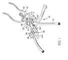
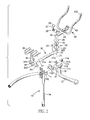
- an exercising machine comprises a support device (10), a pivot device (20), a swinging device (30) and a handle assembly (40).
- the support device (10) comprises a base (11), a collar (12), a transverse leg (13) and two supporting legs (14).
- the base (11) has a top, a bottom, a front end, a rear end, a frame (111), a pivot hole (112), a pillar (113), a panel (114), a fastener (115) and an inserting hole (116).
- the frame (111) is protruded on the bottom and has a through hole.
- the pivot hole (112) is formed in the top.
- the pillar (113) is protruded up from the top near the front end and has a proximal end and a distal end. The proximal end of the pillar (113) is mounted on the top of the base (11).
- the panel (114) is mounted on the distal end of the pillar (113) and has a hole.
- the fastener (115) is extended through the hole and mounted with the panel (114).
- the inserting hole (116) is formed in the top of the base (11) near the rear end.
- the transverse leg (13) is connected with the collar (12) and has a middle.
- the collar (12) is mounted on the middle and connected to the frame (111) on the base (11).
- Each supporting leg (14) is attached to the base (11) near the rear end and has a proximal end, a distal end and a connecting bracket (142).
- the connecting bracket (142) is attached to the proximal end of the supporting leg (14) and mounted onto the base (11).
- the pivot device (20) is mounted with the base (11) and has a pivot post (21), a first washer (22), a board (23), a damping disk (24), a second washer (25), an adjusting disk (26), a spacer (27) and a fixing element (28).
- the pivot post (21) is inserted into the pivot hole (112) in the base (11) and has a proximal end, a distal end and a threaded hole. The proximal end is inserted into the pivot hole (112), and the threaded hole is formed in the distal end.
- the first washer (22) is mounted on the pivot post (21) near the proximal end.
- the board (23) is mounted on the pivot post (21) near the distal end.
- the damping disk (24) is mounted around the pivot post (21), is held on the board (23) and provides a resistance effect to the pivot post (21).
- the second washer (25) is mounted around the pivot post (21) and abuts with the damping disk (24).
- the adjusting disk (26) and the spacer (27) are mounted around the pivot post (21) over the second washer (25).
- the adjusting disk (26) has multiple positioning holes (262) formed through the adjusting disk (26).
- the fixing element (28) is connected to the threaded hole in the pivot post (21), presses against the spacer (27) and has a bottom, a hole, a spring (281) and a positioning stub (282). The hole is formed in the bottom.
- the spring (281) is held inside the hole and abuts against the positioning stub (282).
- the positioning stub (282) is partially extends out from the hole and engages with one of the positioning holes (262).
- the swinging device (30) is connected to the base (11) by the pivot post (21) and has a swinging beam (31), a pillar seat (32), an inserting pillar (33), a holding frame (34), a fastener (35) and two holders (36).
- the swinging beam (31) has a front end, a rear end, a pillar hole (312) and at least one adjusting hole (314).
- the pillar hole (312) is formed through the swinging beam (31) near the front end and corresponds to the inserting hole (116).
- Each adjusting hole (314) is formed through the swinging beam (31).
- the pillar seat (32) is attached to the front end of the swinging beam (31) and has a top, a bottom and a pillar hole (321).
- the pillar hole (321) is formed through the pillar seat (32) and mounted around the pivot post (21).
- the inserting pillar (33) is extended through the pillar hole (312) and selectively into the inserting hole (116), and has a distal end and a proximal end. If the proximal end of the inserting pillar (33) is detached from the inserting hole (116), the swinging beam (31) can be swung relative to the pivot device (20).
- the holding frame (34) is mounted on the swing beam (31) and has a jacket (342), two holding blocks (341) and a positioning hole (344).
- the jacket (342) is mounted around the swinging beam (31).
- the holding blocks (341) are mounted on the jacket (342).
- the positioning hole (344) is formed through the jacket (342) and corresponds to one of the adjusting holes (314).
- the fastener (35) is extended through the positioning hole (344) and the corresponding adjusting hole (314).
- the holders (36) are attached respectively to the holding blocks (341).
- the handle assembly (40) is connected to the swinging device (30) by the pivot post (21) and has a mounting tube (42), a handle (43) and a lateral arm (41).
- the mounting tube (42) is mounted around the pivot post (21) and located between the second washer (25) and the adjusting disk (26).
- the handle (43) has two handlebars (432).
- the lateral arm (41) has a rear end, a front end, a bottom and a fixed hole (412). The rear end is mounted with the mounting tube (42) and the front end is connected to the handle (43).
- the fixed hole (412) is formed on the bottom, and the fastener (115) is inserted into the fixed hole (412).
- the handle assembly (40) can be swung relative to the base (11) opposite to the swinging device (30).
- the distance between the holders (36) and the base (11) can be adjusted by inserting the fastener (35) extending through the positioning hole (344) of the holding frame (34) into one of the adjusting holes (314).
- another embodiment of the exercising machine also comprises a support device (10), a pivot device (20), a swinging device (30) and a handle assembly (40).
- the structure of the another embodiment is mostly the same as the exercising machine above-mention except the follows.
- the support device (10) comprises a base (11), a collar (12), a transverse leg (13) and two supporting legs (14).
- the transverse leg (13) has a mounting shaft forming on the middle of the transverse shaft (13).
- the collar (12) is mounted around the mounting shaft (132) and connected to the frame (111) and has a fastener (122).
- the swinging device (30) is connected to the base (11) by the pivot post (21) and has a first swinging beam (31 A), a frame (37), a second swinging beam (31B), a holding pin (33) and two holders (36).
- the first swinging beam (31A) has a curved front end and a rear end and the frame (37) is attached to the curved front end.
- the second swinging beam (31B) is mounted with the frame (37) and has a curved front end and a rear end.
- the holding pin (33) is mounted with the frame (37).
- the holders (36) are attached respectively to the swinging beams (31A, 31B) to hold user's feet.
- the distance between the two swinging beams (31A, 31B) can be adjusted by the holding pin (33).
- the gradient of the support device (10) can be adjusted by changing the distance between the mounting shaft (132) and the collar (12).
Landscapes
- Health & Medical Sciences (AREA)
- Orthopedic Medicine & Surgery (AREA)
- General Health & Medical Sciences (AREA)
- Physical Education & Sports Medicine (AREA)
- Rehabilitation Tools (AREA)
- Pivots And Pivotal Connections (AREA)
Applications Claiming Priority (1)
| Application Number | Priority Date | Filing Date | Title |
|---|---|---|---|
| CNU2006200029246U CN2865777Y (zh) | 2006-01-20 | 2006-01-20 | 旋摆式运动健身器 |
Publications (1)
| Publication Number | Publication Date |
|---|---|
| EP1810718A2 true EP1810718A2 (de) | 2007-07-25 |
Family
ID=37701477
Family Applications (1)
| Application Number | Title | Priority Date | Filing Date |
|---|---|---|---|
| EP20060020591 Withdrawn EP1810718A2 (de) | 2006-01-20 | 2006-09-29 | Übungsgerät |
Country Status (2)
| Country | Link |
|---|---|
| EP (1) | EP1810718A2 (de) |
| CN (1) | CN2865777Y (de) |
Cited By (3)
| Publication number | Priority date | Publication date | Assignee | Title |
|---|---|---|---|---|
| GB2457035A (en) * | 2008-01-30 | 2009-08-05 | King I Tech Corp | Swinging waist-twisting fitness equipment |
| EP2163280A3 (de) * | 2008-09-08 | 2010-09-08 | Robson Splane | Bauchübungsgerät |
| US7901329B2 (en) | 2007-04-04 | 2011-03-08 | Cheng-Kang Chu | Swinging gymnastic machine |
Families Citing this family (2)
| Publication number | Priority date | Publication date | Assignee | Title |
|---|---|---|---|---|
| WO2008122142A1 (en) * | 2007-04-04 | 2008-10-16 | Jao-Hsing Tsai | A swinging exercising machine |
| CN102327688B (zh) * | 2011-09-13 | 2014-07-09 | 胡江勇 | 扭腰器 |
-
2006
- 2006-01-20 CN CNU2006200029246U patent/CN2865777Y/zh not_active Expired - Fee Related
- 2006-09-29 EP EP20060020591 patent/EP1810718A2/de not_active Withdrawn
Cited By (7)
| Publication number | Priority date | Publication date | Assignee | Title |
|---|---|---|---|---|
| US7901329B2 (en) | 2007-04-04 | 2011-03-08 | Cheng-Kang Chu | Swinging gymnastic machine |
| GB2457035A (en) * | 2008-01-30 | 2009-08-05 | King I Tech Corp | Swinging waist-twisting fitness equipment |
| GB2457035B (en) * | 2008-01-30 | 2010-02-03 | King I Tech Corp | Swinging waist-twisting fitness equipment |
| EP2163280A3 (de) * | 2008-09-08 | 2010-09-08 | Robson Splane | Bauchübungsgerät |
| US7927267B2 (en) | 2008-09-08 | 2011-04-19 | Robson Splane | Abdominal exercise device |
| EP2446937A1 (de) * | 2008-09-08 | 2012-05-02 | Robson Splane | Bauchtrainer |
| US8323160B2 (en) | 2008-09-08 | 2012-12-04 | Robson Splane | Abdominal exercise device |
Also Published As
| Publication number | Publication date |
|---|---|
| CN2865777Y (zh) | 2007-02-07 |
Similar Documents
| Publication | Publication Date | Title |
|---|---|---|
| US5299997A (en) | Horse-riding type exerciser | |
| US6544147B1 (en) | Rocker arm for an electric treadmill | |
| US7455624B2 (en) | Low-impact exercise machine | |
| US6162150A (en) | Foot massaging exercising apparatus | |
| US5865711A (en) | Exercise bicycle | |
| US6123653A (en) | Multifunctional situp exerciser | |
| US5913752A (en) | Total body exercise machine | |
| US7104933B1 (en) | Rower | |
| WO2006110727A3 (en) | Exercise ball mounted for rotation | |
| JP2000317011A (ja) | 室内運動用自転車 | |
| US20060035756A1 (en) | Twist pedals for stepping exercisers | |
| US7137929B2 (en) | Fitness bike | |
| TWM471910U (zh) | 健身車搖擺裝置 | |
| US20050170939A1 (en) | Yoga balance trainer | |
| TW200800336A (en) | Exercise device | |
| WO2008041035A3 (en) | Improved abdominal muscle training apparatus | |
| EP2462996A1 (de) | Übungsgerät mit Stepperbewegung, Drehbewegung oder Stepper- und Drehbewegung | |
| US5895343A (en) | Upper or lower body trainer | |
| US6508745B1 (en) | Stationary exercise bicycle with shock absorption system | |
| US4606538A (en) | Physical exercise device | |
| KR101352397B1 (ko) | 실내용 자전거 운동기구 | |
| US20060128532A1 (en) | Extendable swing arm assembly for a treadmill | |
| US20030060347A1 (en) | Abdominal exercising machine | |
| US5823915A (en) | Exercise bicycle | |
| US20070179022A1 (en) | Surfing exercisers |
Legal Events
| Date | Code | Title | Description |
|---|---|---|---|
| PUAI | Public reference made under article 153(3) epc to a published international application that has entered the european phase |
Free format text: ORIGINAL CODE: 0009012 |
|
| AK | Designated contracting states |
Kind code of ref document: A2 Designated state(s): AT BE BG CH CY CZ DE DK EE ES FI FR GB GR HU IE IS IT LI LT LU LV MC NL PL PT RO SE SI SK TR |
|
| AX | Request for extension of the european patent |
Extension state: AL BA HR MK YU |
|
| 17P | Request for examination filed |
Effective date: 20070801 |
|
| STAA | Information on the status of an ep patent application or granted ep patent |
Free format text: STATUS: THE APPLICATION IS DEEMED TO BE WITHDRAWN |
|
| 18D | Application deemed to be withdrawn |
Effective date: 20090401 |