EP1810826A2 - Machine d'impression de feuilles - Google Patents
Machine d'impression de feuilles Download PDFInfo
- Publication number
- EP1810826A2 EP1810826A2 EP07000754A EP07000754A EP1810826A2 EP 1810826 A2 EP1810826 A2 EP 1810826A2 EP 07000754 A EP07000754 A EP 07000754A EP 07000754 A EP07000754 A EP 07000754A EP 1810826 A2 EP1810826 A2 EP 1810826A2
- Authority
- EP
- European Patent Office
- Prior art keywords
- sheet
- printing
- fed
- formless
- printing device
- Prior art date
- Legal status (The legal status is an assumption and is not a legal conclusion. Google has not performed a legal analysis and makes no representation as to the accuracy of the status listed.)
- Withdrawn
Links
Images


Classifications
-
- B—PERFORMING OPERATIONS; TRANSPORTING
- B41—PRINTING; LINING MACHINES; TYPEWRITERS; STAMPS
- B41J—TYPEWRITERS; SELECTIVE PRINTING MECHANISMS, i.e. MECHANISMS PRINTING OTHERWISE THAN FROM A FORME; CORRECTION OF TYPOGRAPHICAL ERRORS
- B41J3/00—Typewriters or selective printing or marking mechanisms characterised by the purpose for which they are constructed
- B41J3/54—Typewriters or selective printing or marking mechanisms characterised by the purpose for which they are constructed with two or more sets of type or printing elements
- B41J3/546—Combination of different types, e.g. using a thermal transfer head and an inkjet print head
-
- B—PERFORMING OPERATIONS; TRANSPORTING
- B41—PRINTING; LINING MACHINES; TYPEWRITERS; STAMPS
- B41F—PRINTING MACHINES OR PRESSES
- B41F19/00—Apparatus or machines for carrying out printing operations combined with other operations
- B41F19/007—Apparatus or machines for carrying out printing operations combined with other operations with selective printing mechanisms, e.g. ink-jet or thermal printers
Definitions
- the invention relates to a sheet-fed printing machine according to the preamble of claim 1.
- pressure-free printing devices are increasingly used, which are preferably used for the individualization of printed products produced by offset printing with, for example, barcodes, numbering or other markings.
- Such printing formless printing devices are also referred to as non-impact print (NIP) printing devices and can be embodied, for example, as inkjet printing devices which have at least one inkjet print head, wherein the or each inkjet print head according to the so-called continuous inkjet principle, The drop-on-demand inkjet principle, the thermal inkjet principle or any other inkjet principle can work.
- the pressure-formless or NIP printing devices can also be designed as laser printing devices.
- a sheet-fed printing machine in which a designed as an inkjet printing device or as a laser printing device, pressure-free printing device is integrated in an offset printing unit of the sheet-fed press.
- the pressure-formless printing device with respect to a sheet-guiding impression cylinder in the area after the passage of sheet is arranged by a pressure gap formed by the impression cylinder and a blanket cylinder.
- the printing machine according to DE 197 04 003 A1 In particular, the printing of printed sheets with a high rigidity in the area of the inkjet printing device or laser printing device is problematic.
- Another sheet-fed press with a built-in pressure-free printing device is from the DE 195 14 259 A1 known, the pressure-formless printing device seen in the transport direction of the sheet seen behind the last offset printing unit and in the transport direction of the sheet seen in front of a boom of the sheet-fed press integrated into this according to this prior art.
- the present invention is based on the problem to provide a novel sheet-fed printing machine.
- the or each pressure-formless printing device is integrated in the sheet-fed printing machine in the area of the feeder.
- the or each pressure-formless printing device in the area of the feeder of the sheet-fed printing machine into the same. Accordingly, in the context of the present invention, the printing of printed sheets with the help of or any pressure-free printing device at a time, which is prior to printing the sheet in the preferably formed as offset printing units of the sheet-fed printing press.
- the printing formless printing devices can be arranged with a small distance to the printed sheet, without rolling on the sheet to be printed on the sheet Sheet guide rollers are required, which on the one hand affect the print quality and on the other hand limit the printable in the range of or any pressure-free device width of the sheet.
- Fig. 1 shows a schematic representation of a sheet-fed printing machine 10, wherein the sheet-fed printing machine 10 comprises a feeder 11, a plurality formed as offset printing units printing units 12, a printing units 12 downstream coating unit 13 and the coating unit 13 downstream boom 14.
- the feeder 11 is used for feeding sheet to be printed in the sheet-fed press 10, wherein the sheets are moved through the printing units 12 and the coating unit 13 and printed in the same with a print sheet for all the same or unchanging and thus static printed image.
- printed signatures are discharged from the sheet-fed printing press to form a delivery stack 15.
- the sheet-fed printing machine 10 is designed as a so-called turning machine, which serves the two-sided printing of printed sheets in the so-called perfecting.
- a arranged between the first two printing units 12 transfer cylinder is this formed as a turning cylinder 16.
- At least one pressure-formless printing device is integrated, which preferably serves to print the printed sheet with a dynamic or variable print image.
- the or each pressure-formless printing device is integrated in the area of the feeder 11 in the sheet-fed press 10, wherein in Fig. 1 possible mounting positions 17 and 18 are shown schematically for the or each pressure-formless printing device. In both installation positions 17 and 18, the printed sheets are printed in the region of the feeder 11 via the or each pressure-formless printing device from above.
- the installation position 18 is preferred for each pressure-formless printing device, namely above an investment table 19, via which printed sheets lifted from an feeder stack 20 are fed to the first printing unit 12 of the printing press.
- the printed sheets are guided on their underside by at least one suction belt, so that the printing sheets of the or each printing forme printing device on an upper side thereof are printable, namely over the entire format width and format length thereof.
- the sheets are flat or flat. It can be maintained a small distance between the or each pressure-free printing device and the sheet and thus a high print quality can be provided.
- a pressure-free printing device is integrated into the feeder 11 in the installed position 18 above an investment table 19, the installation position along the contact table 19 can be freely selected.
- the printing forme printing device then at least a leading edge and a side edge of the sheet must then be detected and evaluated to print the sheets in the desired zones thereof.
- the sensors required to detect the leading edge and side edge may be provided via infrared or ultrasonic sensors or capacitive sensors.
- the installation position 17 is preferred for the or each pressure-formless printing device, namely above a contact plate of the flaker feeder, not shown in FIG. 1, wherein the printed sheets are separated in the region of the contact plate and detected by a so-called pre-gripper 21 and the first printing unit 12 of the sheet-fed printing machine 10 are supplied.
- the printed sheets of the or each printing formless printing device over the entire format width and format length can be printed with a dynamic or variable printed image.
- a printing formless printing device is integrated in the installation position 17 adjacent to the pre-gripper 21 in the feeder 11, at least one leading edge of the printed sheet must be detected and evaluated in order to control the printing form free printing device in the desired zones thereof to print.
- the required for detecting the leading edge sensor can be provided in turn via infrared or ultrasonic sensors or capacitive sensors.
- a sheet guiding device is preferably positioned which can be displaced into regions or zones of the printed sheets which are not to be printed by the printing-formless printing device.
- At least one characteristic curve is stored in a control device of the printing-form-free printing device which depends on substrate characteristics such as the grammage and / or the grain direction and / or the stiffness of the sheet Printed sheet is.
- the pressure-formless printing device is then controlled based on one of these characteristics.
- the characteristic curves are determined in advance for printed sheets from different substrates.
- the or each in the sheet-fed printing machine 10 integrated pressure-free printing device is preferably designed as an inkjet printing device or laser printing device, said printing devices seen transversely to the transport direction of the sheet seen a plurality of juxtaposed inkjet printheads or laser printheads and seen in the transport direction of the sheet a plurality of successively arranged
- inkjet printheads or laser printheads arranged array-like or matrix-like to each other and preferably interconnected on the control side.
- the number of print heads required transversely to the printing direction is primarily defined by the desired total print width relative to the given print width of the print head used.
- the required number of printheads in the transport direction of the sheet is, however, determined by the fact that the desired printing speed is greater than the given printing speed of a printhead and in that a plurality of inks are to be applied to the sheets by means of pressure-free printing device. Furthermore, the number of print heads in the transport direction of the print sheets is defined by the desired print resolution in relation to the given print resolution of the print head used.
- the printing units 12 and the coating unit 13 of the sheet-fed printing press 10 serve to print the printed sheets with a static, identical for all printed image.
- the or each in the area of the investor 11 integrated in the sheet-fed press 10 formless device is used to print the sheet with a dynamic or variable print image, the printing with the dynamic or variable print image inline for printing the sheet with the static image, namely, in time before printing the sheet in the printing units 12 and the coating unit 13th
- Fig. 2 shows the application of the invention in a sheet-fed press 22, in the transport direction of the sheet seen after the feeder 11 designed as a flexo printing unit printing unit 23 and seen in the transport direction of the sheet before the boom 14, a coating unit 24 is arranged, and wherein between the flexographic printing unit 23 and the coating unit 24 two drying devices 25 are positioned.
- At least one pressure-formless printing device in the region of the feeder 11 is integrated into the sheet-fed printing press 22, namely either in the area of the installation position 17 or in the area of the installation position 18, so that reference may be made to the embodiments of the embodiment of FIG ,
- the installation position 17 is preferred in the case of a feeder designed as a flaker feeder and the installation position 18 in the case of a feeder designed as a single-sheet feeder.
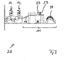
- Fig. 3 shows a section of a further sheet-fed printing machine 26 according to the invention, in which the feeder 11 is designed as a roll-sheet feeder, and wherein the roll sheet feeder 11 seen in the transport direction of the sheet seen downstream of two printing units 12 designed as offset printing units are.
- the roll-bow feeder 11 comprises a sheet-roll cutter 27, also referred to as an inline sheeter. In the area of the sheet-roll cutter 27, printed sheets are cut from a roll-shaped printing material 28, which are then fed via a feed table 19 to the first printing unit 12 of the sheet-fed printing machine 26.
- the or each pressure-formless printing device is preferably integrated into the feeder 11 of the sheet-fed printing press 26 according to the invention at the installation position 29 schematically illustrated in FIG.
- the printed sheets can be printed over the entire format width and format length from above with a variable or variable print image.
- the or each pressure-formless printing device of the sheet-fed printing machine can be disassembled, in such a way that the or each pressure-formless printing device can be used on a different sheet-fed press or within the same sheet-fed press at different mounting positions.
- the or each pressure-formless printing device has a supply side, namely mechanical or printing ink side, and a control side, namely electrical or electronic, interface, via which the or any pressure-free printing device can be connected to an ink supply system or to a control device of the respective printing press ,
- pressure-free printing devices are integrated into a sheet-fed printing machine at several installation positions, then the electrical and mechanical interfaces for these printing devices can be centralized.
- To the or each pressure-formless printing device leading supply lines be it electrical supply lines or mechanical or pressure-color side supply lines can either be permanently installed on the sheet-fed press according to the invention or be brought to the sheet-fed press mobile. Due to the dismantling of the or each printing formless printing device of the sheet-fed printing machine according to the invention maintenance and cleaning of the printing formless printing devices outside the range of the sheet-fed press can be performed.
- the printing formless printing device is preferably arranged downstream of a drying device or curing device and / or a suction device, wherein the drying device serves to dry the printing ink applied via the printing formless printing device and the suction device to remove solvent vapors from the ink applied via the printing plate free printing device.
- the pressure-formless printing device is arranged pivotably in the region of the feeder 11, preferably on a feeder arm, which engages on a side frame of the feeder or the first printing unit. As a result, the feeder 11 is freely accessible for setup work.
Landscapes
- Feeding Of Articles By Means Other Than Belts Or Rollers (AREA)
- Rotary Presses (AREA)
- Supply, Installation And Extraction Of Printed Sheets Or Plates (AREA)
Applications Claiming Priority (1)
| Application Number | Priority Date | Filing Date | Title |
|---|---|---|---|
| DE102006002302.1A DE102006002302B4 (de) | 2006-01-18 | 2006-01-18 | Bogendruckmaschine |
Publications (2)
| Publication Number | Publication Date |
|---|---|
| EP1810826A2 true EP1810826A2 (fr) | 2007-07-25 |
| EP1810826A3 EP1810826A3 (fr) | 2011-03-09 |
Family
ID=38023763
Family Applications (1)
| Application Number | Title | Priority Date | Filing Date |
|---|---|---|---|
| EP07000754A Withdrawn EP1810826A3 (fr) | 2006-01-18 | 2007-01-16 | Machine d'impression de feuilles |
Country Status (2)
| Country | Link |
|---|---|
| EP (1) | EP1810826A3 (fr) |
| DE (1) | DE102006002302B4 (fr) |
Cited By (4)
| Publication number | Priority date | Publication date | Assignee | Title |
|---|---|---|---|---|
| WO2009036991A1 (fr) * | 2007-09-19 | 2009-03-26 | Manroland Ag | Procédé d'impression d'une matière à imprimer |
| EP2111985A1 (fr) * | 2008-04-21 | 2009-10-28 | WIFAG Maschinenfabrik AG | Imprimantes de journaux dotée d'un dispositif d'impression supplémentaire et procédé d'impression variable durant la production de journaux |
| WO2010086263A1 (fr) * | 2009-01-30 | 2010-08-05 | Manroland Ag | Presse à feuilles |
| EP3072690A1 (fr) * | 2015-03-25 | 2016-09-28 | Heidelberger Druckmaschinen AG | Machine d'impression de feuilles et station d'acceleration |
Families Citing this family (13)
| Publication number | Priority date | Publication date | Assignee | Title |
|---|---|---|---|---|
| DE102009000519A1 (de) | 2009-01-30 | 2010-08-05 | Manroland Ag | Bogendruckmaschine |
| DE102009000518B4 (de) | 2009-01-30 | 2023-11-16 | manroland sheetfed GmbH | Bogendruckmaschine |
| DE102009000521A1 (de) | 2009-01-30 | 2010-08-05 | Manroland Ag | Bogendruckmaschine |
| DE102009000513B4 (de) | 2009-01-30 | 2024-04-18 | manroland sheetfed GmbH | Bogendruckmaschine |
| DE102009000523A1 (de) | 2009-01-30 | 2010-08-05 | Manroland Ag | Bogendruckmaschine |
| DE102010010785B4 (de) * | 2010-03-09 | 2012-04-12 | Fritz Egger Gmbh & Co. Og | Verfahren und Vorrichtung zur Herstellung von Dekorpapier zum Beschichten von plattenförmigen Grundkörpern |
| DE102012200650A1 (de) | 2011-02-08 | 2012-08-09 | Manroland Ag | Bogendruckmaschine |
| DE102015116030A1 (de) | 2014-10-02 | 2016-04-07 | manroland sheetfed GmbH | Einrichtung zum Codieren von Druckbogen in einer Bogendruckmaschine |
| DE102015017156B4 (de) | 2015-04-30 | 2023-11-30 | Koenig & Bauer Ag | Verfahren zum Betrieb einer Transporteinrichtung zum Transport von Bogen in einer Anordnung von mehreren jeweils Bogen bearbeitenden Bearbeitungsstationen |
| DE102016125960A1 (de) | 2015-12-31 | 2017-07-06 | manroland sheetfed GmbH | Inkjet-Druckeinrichtung an einer Bogenoffsetdruckmaschine |
| DE102018106529A1 (de) * | 2018-03-20 | 2019-09-26 | Manroland Goss Web Systems Gmbh | Druckmaschine und Verfahren zum Überwachen einer Druckmaschine |
| CN114905839A (zh) | 2021-02-09 | 2022-08-16 | 海德堡印刷机械股份公司 | 用于处理基材幅面的设备和方法 |
| DE102022105615A1 (de) | 2022-03-10 | 2023-09-14 | Koenig & Bauer Ag | Bogenverarbeitende Maschine und Verfahren zur Kennzeichnung und Nachverfolgung von Bogen |
Citations (2)
| Publication number | Priority date | Publication date | Assignee | Title |
|---|---|---|---|---|
| DE19514259A1 (de) | 1995-04-15 | 1996-10-17 | Roland Man Druckmasch | Verfahren zum Eindrucken von Strichcodes in Druckbogen und Vorrichtung zur Durchführung des Verfahrens |
| DE19704003A1 (de) | 1997-02-04 | 1998-08-06 | Kba Planeta Ag | Verfahren und Vorrichtung zum Eindrucken von individualisierenden Kennzeichnungen |
Family Cites Families (10)
| Publication number | Priority date | Publication date | Assignee | Title |
|---|---|---|---|---|
| US4370665A (en) * | 1981-04-27 | 1983-01-25 | The Mead Corporation | Paper transport for a printer test unit |
| DE19629370A1 (de) * | 1996-07-20 | 1998-01-22 | Heidelberger Druckmasch Ag | Rotationsdruckmaschine mit einer Einrichtung zum Behandeln der Oberfläche von Bogen |
| DE19745136B4 (de) * | 1996-10-17 | 2007-07-12 | Heidelberger Druckmaschinen Ag | Rotationsbogendruckmaschine |
| JP2946201B2 (ja) * | 1997-04-17 | 1999-09-06 | 株式会社東京機械製作所 | 付加印刷装置付き輪転機及び付加印刷装置付き印刷ユニット |
| US6022104A (en) * | 1997-05-02 | 2000-02-08 | Xerox Corporation | Method and apparatus for reducing intercolor bleeding in ink jet printing |
| DE10103039B4 (de) * | 2001-01-24 | 2015-07-02 | Heidelberger Druckmaschinen Ag | Verfahren zur Einstellung drucktechnischer und anderer jobabhängiger Parameter einer Druckmaschine |
| DE102004002132A1 (de) * | 2004-01-15 | 2005-08-11 | Man Roland Druckmaschinen Ag | Einrichtung zur Erzeugung einer Beschichtung von Druckprodukten einer Druckmaschine |
| DE102005011568A1 (de) * | 2004-04-13 | 2005-11-17 | Man Roland Druckmaschinen Ag | Produktionsverfahren für eine Prägeeinrichtung in einer Bogendruckmaschine |
| DE102005021185A1 (de) * | 2004-05-03 | 2005-11-24 | Man Roland Druckmaschinen Ag | Verfahren und Vorrichtung zur Applikation von Deckweiß und Effektschichten auf einen Bedruckstoff |
| DE202005011939U1 (de) * | 2005-07-29 | 2005-10-13 | Man Roland Druckmaschinen Ag | Bogendruckmaschine |
-
2006
- 2006-01-18 DE DE102006002302.1A patent/DE102006002302B4/de not_active Expired - Lifetime
-
2007
- 2007-01-16 EP EP07000754A patent/EP1810826A3/fr not_active Withdrawn
Patent Citations (2)
| Publication number | Priority date | Publication date | Assignee | Title |
|---|---|---|---|---|
| DE19514259A1 (de) | 1995-04-15 | 1996-10-17 | Roland Man Druckmasch | Verfahren zum Eindrucken von Strichcodes in Druckbogen und Vorrichtung zur Durchführung des Verfahrens |
| DE19704003A1 (de) | 1997-02-04 | 1998-08-06 | Kba Planeta Ag | Verfahren und Vorrichtung zum Eindrucken von individualisierenden Kennzeichnungen |
Cited By (8)
| Publication number | Priority date | Publication date | Assignee | Title |
|---|---|---|---|---|
| WO2009036991A1 (fr) * | 2007-09-19 | 2009-03-26 | Manroland Ag | Procédé d'impression d'une matière à imprimer |
| CN101815622B (zh) * | 2007-09-19 | 2014-10-29 | 曼罗兰公司 | 用于印刷承印材料的方法 |
| EP2193032B1 (fr) * | 2007-09-19 | 2018-12-26 | manroland Goss web systems GmbH | Procédé d'impression d'une matière à imprimer |
| EP2111985A1 (fr) * | 2008-04-21 | 2009-10-28 | WIFAG Maschinenfabrik AG | Imprimantes de journaux dotée d'un dispositif d'impression supplémentaire et procédé d'impression variable durant la production de journaux |
| WO2009130078A1 (fr) * | 2008-04-21 | 2009-10-29 | Wifag Maschinenfabrik Ag | Machine d'impression de journaux avec dispositif d'impression additionnelle et procédé d'impression variable dans la production des journaux |
| WO2010086263A1 (fr) * | 2009-01-30 | 2010-08-05 | Manroland Ag | Presse à feuilles |
| EP3072690A1 (fr) * | 2015-03-25 | 2016-09-28 | Heidelberger Druckmaschinen AG | Machine d'impression de feuilles et station d'acceleration |
| CN106004100A (zh) * | 2015-03-25 | 2016-10-12 | 海德堡印刷机械股份公司 | 具有加速站的页张印刷机 |
Also Published As
| Publication number | Publication date |
|---|---|
| EP1810826A3 (fr) | 2011-03-09 |
| DE102006002302B4 (de) | 2025-11-06 |
| DE102006002302A1 (de) | 2007-07-19 |
Similar Documents
| Publication | Publication Date | Title |
|---|---|---|
| EP1810826A2 (fr) | Machine d'impression de feuilles | |
| DE102009000518B4 (de) | Bogendruckmaschine | |
| EP2574463B1 (fr) | Machine d'impression à feuilles | |
| EP2982510B1 (fr) | Unite de jet d'encre modulaire dans une imprimante hybride | |
| DE20006513U1 (de) | Bogen-Rotationsdruckmaschine | |
| EP1810825A2 (fr) | Machine d'impression de feuilles | |
| DE102009002580A1 (de) | Druckmaschine, insbesondere Bogenoffsetdruckmaschine | |
| DE102009000513B4 (de) | Bogendruckmaschine | |
| DE102006002304A1 (de) | Bogendruckmaschine | |
| EP3201000B1 (fr) | Dispositif de codage de feuilles à imprimer dans une presse à feuilles | |
| DE19921632B4 (de) | Rollenrotations-Druckmaschine mit einer Vorrichtung zum Umlenken einer nassen oder feuchten bedruckten Bahn | |
| DE102005019533B4 (de) | Druckmaschine und Verfahren zum Betreiben der Druckmaschine zur Inline-Herstellung individualisierter Druckerzeugnisse | |
| EP1151860B1 (fr) | Machine pour imprimer des feuilles | |
| WO2010086263A1 (fr) | Presse à feuilles | |
| WO2010086262A1 (fr) | Presse à feuilles | |
| EP1872946B1 (fr) | Cylindre de guidage de feuille avec un habillage pour une machine de traitement | |
| WO2010086205A1 (fr) | Presse à feuilles | |
| DE102005016309B4 (de) | Bogendruckmaschine | |
| DE20113639U1 (de) | Beschichtungsmaschine zum Veredeln von Druckbogen | |
| DE102019131799A1 (de) | Bearbeitungsmaschine mit zumindest einer Reinigungsvorrichtung und Verfahren zur Reinigung | |
| EP2046578A2 (fr) | Unité d'impression d'une imprimante rotative à bobines | |
| DE102007044622B4 (de) | Rollendruckmaschine | |
| EP1106350B1 (fr) | Dispositif pour imprimer de feuilles recto-verso dans de machines d'impression offset à feuille | |
| WO2010086264A1 (fr) | Presse à feuilles | |
| DE202005011939U1 (de) | Bogendruckmaschine |
Legal Events
| Date | Code | Title | Description |
|---|---|---|---|
| PUAI | Public reference made under article 153(3) epc to a published international application that has entered the european phase |
Free format text: ORIGINAL CODE: 0009012 |
|
| AK | Designated contracting states |
Kind code of ref document: A2 Designated state(s): AT BE BG CH CY CZ DE DK EE ES FI FR GB GR HU IE IS IT LI LT LU LV MC NL PL PT RO SE SI SK TR |
|
| AX | Request for extension of the european patent |
Extension state: AL BA HR MK YU |
|
| RIN1 | Information on inventor provided before grant (corrected) |
Inventor name: SCHOELZIG, JUERGEN, DIPL.-ING. Inventor name: KLITZA, ALEXANDER, DIPL.-ING. Inventor name: IHME, ANDREAS, DIPL.-ING. |
|
| RAP1 | Party data changed (applicant data changed or rights of an application transferred) |
Owner name: MANROLAND AG |
|
| PUAL | Search report despatched |
Free format text: ORIGINAL CODE: 0009013 |
|
| AK | Designated contracting states |
Kind code of ref document: A3 Designated state(s): AT BE BG CH CY CZ DE DK EE ES FI FR GB GR HU IE IS IT LI LT LU LV MC NL PL PT RO SE SI SK TR |
|
| AX | Request for extension of the european patent |
Extension state: AL BA HR MK RS |
|
| RIC1 | Information provided on ipc code assigned before grant |
Ipc: B41F 7/06 20060101ALI20110202BHEP Ipc: B41J 3/54 20060101ALI20110202BHEP Ipc: B41F 13/46 20060101AFI20070523BHEP |
|
| AKY | No designation fees paid | ||
| REG | Reference to a national code |
Ref country code: DE Ref legal event code: R108 |
|
| REG | Reference to a national code |
Ref country code: DE Ref legal event code: R108 Effective date: 20111116 |
|
| STAA | Information on the status of an ep patent application or granted ep patent |
Free format text: STATUS: THE APPLICATION IS DEEMED TO BE WITHDRAWN |
|
| 18D | Application deemed to be withdrawn |
Effective date: 20110910 |