EP1811067A2 - Dispositif de réglage du rapport d'armure pour un métier à tisser - Google Patents
Dispositif de réglage du rapport d'armure pour un métier à tisser Download PDFInfo
- Publication number
- EP1811067A2 EP1811067A2 EP06026202A EP06026202A EP1811067A2 EP 1811067 A2 EP1811067 A2 EP 1811067A2 EP 06026202 A EP06026202 A EP 06026202A EP 06026202 A EP06026202 A EP 06026202A EP 1811067 A2 EP1811067 A2 EP 1811067A2
- Authority
- EP
- European Patent Office
- Prior art keywords
- patterns
- shed
- frames
- heald
- loom
- Prior art date
- Legal status (The legal status is an assumption and is not a legal conclusion. Google has not performed a legal analysis and makes no representation as to the accuracy of the status listed.)
- Withdrawn
Links
Images





Classifications
-
- D—TEXTILES; PAPER
- D03—WEAVING
- D03C—SHEDDING MECHANISMS; PATTERN CARDS OR CHAINS; PUNCHING OF CARDS; DESIGNING PATTERNS
- D03C19/00—Methods or devices concerned with designing or making patterns, not provided for in other groups of this subclass
- D03C19/005—Electronic
-
- D—TEXTILES; PAPER
- D03—WEAVING
- D03J—AUXILIARY WEAVING APPARATUS; WEAVERS' TOOLS; SHUTTLES
- D03J1/00—Auxiliary apparatus combined with or associated with looms
- D03J1/005—Displays or displaying data
Definitions
- the present invention relates to a loom, and, more particularly, to a shed pattern setting device in a loom including a shedding machine that can electrically control individual movements of a plurality of heald frames.
- the heald frames are operated as a result of driving the shedding machine in accordance with shed patterns in which vertical positions of the respective heald frames for every loom cycle are indicated over a weaving cycle.
- a shedding machine such as an electronic dobby shedding machine or an electric shedding machine
- the shedding machine is driven in accordance with previously set shed patterns. This causes each heald frame to be driven so as to move vertically, so that a shed is formed in a warp to perform weaving.
- FIG. 9A Examples of the aforementioned shed patterns are shown in Fig. 9A.
- the illustration shows set states of the shed patterns of a loom that performs weaving using 20 heald frames. More specifically, the set states of the illustrated shed patterns regarding positions (maximally raised position/maximally lowered position) of the respective heald frames (that is, the first heald frame to the twentieth heald frame) for each shed step (that is, a weaving cycle) are shown in matrix form over the plurality of shed steps. Therefore, the columns of the illustrated shed patterns represent driving patterns of the respective heald frames that advance every weaving cycle.
- the above-described shed patterns are formed by an operator that forms (edits) the shed patterns, and are set by a setting unit that is attached to a display device of the loom.
- the operator forms the shed patterns with a shed pattern setting device.
- the operator sets the positions (maximally raised position/maximally lowered position) of the respective heald frames for every shed step at an editing screen that is provided at a display screen of the shed pattern setting device.
- the above-described setting operation is performed by changing a display mode (such as display color) of a box corresponding to its associated heald frame for each shed step.
- the setting is performed as follows.
- the display mode of the box corresponding to its associated heald frame set at its maximally raised position is changed to distinguish the display mode of the heald frame set at its maximally raised position from the display mode of the heald frame set at its maximally lowered position.
- the shed patterns set in this way are displayed differently when they are set at their maximally raised positions from when they are set their maximally lowered positions, it is possible to easily visually recognize the relationship between the driving patterns of the heald frames.
- the aforementioned changing of the display mode of each box is performed by, for example, putting a cursor at the box and operating a button.
- a personal computer may be used, instead of the display device (such as a display device including a touch-panel display unit) provided at the loom, to form the aforementioned shed patterns.
- the shed patterns are read into the setting device at the loom through a storage medium (such as a memory card) or LAN to set the shed patterns.
- all of the plurality of head frames (20 frames in the illustrated example) are not necessarily used to weave a non-selvage portion of a cloth.
- some (such as the 18th to 20th heald frames) of the first to twentieth heald frames may be used for weaving a selvage portion of the cloth.
- the heald frames used to weave selvage portions may be driven in accordance with driving patterns that are the reverse of driving patterns set in accordance with the driving patterns of the heald frames used to weave the non-selvage portion of the cloth (such as driving patterns in which the upper and lower positions of the heald frames are reversed).
- the heald frames used to weave the non-selvage portion of the cloth are hereunder referred to as the "non-selvage frames.”
- the driving patterns that are set for the selvage frames are patterns in which the setting of the upper and lower positions are reversed as compared to those of the driving patterns set in accordance with the driving patterns of the non-selvage frames shown in Fig. 9A.
- the driving patterns of some of the heald frames are set so as to be the reverse of the patterns that are set in accordance with the driving patterns of the other heald frames (such driving patterns of some of the heald frames are hereunder referred to as the "reversed patterns")
- the reversed patterns in a related method of setting shed patterns, it is necessary to set the patterns of the some of the heald frames irregularly with respect to those of the other heald frames while checking the columns of the some of the heald frames.
- the task of forming the shed patterns by this setting method has problems in that it is very complicated, is troublesome to carry out, and requires time. In particular, the problems become more noticeable as the shed patterns become sophisticated.
- Japanese Unexamined Patent Application Publication No. 4-263644 discloses the process of reversing and outputting a set pattern (that is, a shed pattern) when driving an electronic dobby machine.
- a set pattern that is, a shed pattern
- the document only discloses the process of completely reversing and outputting the set shed pattern, that is, it does not disclose the process of partly reversing a temporarily formed shed pattern at an editing screen.
- Reversing patterns in the invention of the application covers a case in which patterns are reversed with respect to a central line in a column direction of the patterns disposed in a matrix form within a specified range, in addition to the case in which setting states regarding the positions (maximally raised position/maximally lowered position) of heald frames are reversed.
- the shed patterns when forming shed patterns partly including reversed patterns, the shed patterns are not formed by assuming the reversed state from the beginning. Rather, portions to be reversed are set in a regular state in correspondence with the other portions. After completing this setting operation, a range of the portions to be reversed is specified, so that the patterns can be changed (reversed) by one operation. Therefore, the shed patterns can be easily formed in a short time.
- Figs. 1 to 4 show an embodiment of the present invention.
- the reversed patterns set as driving patterns of the selvage frames are patterns in which set states of vertical positions of the heald frames are the reverse of those of vertical positions of patterns set in correspondence with shed patterns of non-selvage frames.
- the shed patterns are formed with a personal computer, and the formed shed patterns are set on a display device at the loom through a storage medium (such as a memory card). Therefore, in the embodiment, a combination of, for example, a display 41 (corresponds to a display unit), a personal computer body 42 (to be more precise, includes a pattern formation program (software) that is executed at the personal computer body), a keyboard 43, and a mouse 44 corresponds to a shed pattern setting device 40.
- the personal computer body 42 corresponds to controlling means.
- the shed patterns that are formed with the shed pattern setting device 40 and that are stored in a storage medium MC are inserted into and read by a reading unit 21 at the display device 20 of the loom through the storage medium MC, and is stored in a setting unit 22 through a CPU 23 (Fig. 4).
- the shed patterns that are stored in the setting unit 22 are read out from the setting unit 22 by the CPU 23, and the read out shed patterns can be displayed on a display unit 24.
- the shed patterns that are stored in the setting unit 22 are output to a main controlling device 10 through the CPU 23 in accordance with a request from the main controlling device 10 of the loom.
- the main controlling device 10 outputs a signal that is in accordance with a selection state (that is, a state in which either a maximally raised position or a maximally lowered position is selected) of each heald frame 30a, to a shedding machine 30 for each weaving cycle. Then, the shedding machine 30 moves each heald frame 30a vertically in a predetermined timing on the basis of the signal from the main controlling device 10.
- the forming operation of the shed patterns will hereunder be described as being carried out on the display unit (display) 41 of the shed pattern setting device 40.
- the operator uses the personal computer body 42 (serving as controlling means) to display a pattern editing screen 50 (shown in Fig. 1) on a display screen of the display unit 41.
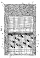
- a pattern editing screen 50 shown in Fig. 1
- the pattern editing screen 50 shown in Fig. 1 is in a state in which the shed patterns are already set, in an initial state, each box 51 disposed in a matrix is in a colorless (white) display state.
- a section of the screen 50 where the boxes 51 are disposed in a matrix at the left side of the screen (this section will hereunder be referred to as the "box section 55") is where the shed patterns are formed.
- Each number in a numerical column 52 provided above the box section 55 indicates a frame number (frame no.) of its associated heald frame 30a corresponding to the column of its associated box 51.
- the boxes 51 under no. 1 represent driving patterns of the first heald frame 30a
- the boxes 51 under no. 20 represent driving patterns of the 20th heald frame 30a.
- Each number in a numerical column 53 provided on the left of the box section 55 represents a step number of the shed patterns.
- Each step number of the shed patterns represents the order of shed states through which the shed patterns progress in one weaving cycle. Therefore, each row of the box section 55 represents the vertical position (selection state) of each heald frame 30a during warp shedding for each weaving cycle.
- a display box 54 which is provided at the top portion in the pattern editing screen 50, indicates the number of heald frames that are used in weaving.
- a display frame 61 indicates information related to the heald frame 30a that is specified by a cursor 57. As illustrated, in the embodiment, the number of head frames used in weaving is 20. In addition, in the embodiment, of the 20 heald frames 30a, or the 1st to the 20th heald frames 30a, the 18th to the 20th heald frames 30a are used as the selvage frames. Therefore, when the cursor 57 is put at any one of the numbers 1 to 17 among the numbers in the numerical column 52, the display frame 61 displays "non-selvage frame" as in the illustrated example. In contrast, when the cursor 57 is put at any one of the numbers 18 to 20, the display frame 61 displays "selvage frame.”
- the shed patterns are formed, that is, the driving pattern of each heald frame is set by confirming whether each heald frame is set at its maximally raised position or its maximally lowered position for every shed step during warp shedding, to change the display mode (such as display color) of each box 51 of the heald frame at its maximally raised position.
- the display mode is changed by using a cursor 56 at a predetermined box 51 and operating a button.
- the positional operation of the cursor 56 is performed by operating the mouse 44 to operate a cursor movement button 62 (provided on the right side in the pattern editing screen 50) with a mouse pointer (not shown) or by operating a cursor key of the keyboard 43.
- the display mode is changed by operating an upper position specification button 63a or a lower position specification button 63b (both of which are provided on the right side in the pattern editing screen 50) or by operating a particular key of the keyboard 43 to which a position specification operation is allotted. If possible, the display mode may be changed by putting the mouse pointer directly at a box 51 and clicking the box 51.
- the driving pattern of each heald frame is set by the operations described above.
- the operator performs the above-described operations while confirming the vertical position where each heald frame is set for each shed step (each weaving cycle). If, as shown in Fig. 9A, the shed patterns are as a whole regular, such shed pattern setting operation can be easily carried out. However, as mentioned above, when some of the patterns are set as reversed patterns, the setting operation becomes complicated. Therefore, in the present invention, a program that reverses patterns of a specified range is set with respect to the controlling means (personal computer body) 42 to facilitate the forming of the shed patterns including the reversed patterns described above.
- each heald frame 30a for every weaving cycle is set in accordance with a pattern having a predetermined regularity at the pattern editing screen 50, without the operator being conscious of the selvage frames and the reversed patterns.
- shed patterns to be reversed that is, the driving patterns of the 18th heald frame to 20th heald frame are specified.
- the specification of a range is carried out by, for example, operating a range specification button 64 (provided at a lower portion in the pattern editing screen 50) and causing the controlling means 42 to be set in a range setting mode.
- a program that performs such a range specification is also set at the controlling means 42.
- the pattern editing screen 50 is set in the range setting mode by the controlling means 42 as a result of operating the range specification button 64 or by operating a particular key of the keyboard 43 to which a range specification operation is allotted.
- the cursor 56 is moved by the aforementioned operation to specify a beginning point and an end point, so that the range is specified.
- the range can also be specified by operating the mouse 44 and dragging the range with the mouse pointer.
- the range of the driving patterns of the selvage frames is specified (that is, the range specified portion is in a state in which its display mode (such as color) is changed with respect to the other portions).
- a frame reversal button 65 (provided at the lower portion of the pattern editing screen) is operated or a particular key of the keyboard 43 to which the frame reversal operation is allotted is operated.
- the reversal program for reversing the set state of the vertical position of each pattern in the specified range is executed.
- the shed patterns of the selvage frames are changed from the state in which they are set in accordance with the shed patterns of the non-selvage frames to the state (shown in Fig. 3) in which the set states of the vertical positions are reversed, thereby ending the forming operation of the shed patterns.
- the present invention is not limited thereto.
- the above-described range specification is not limited to that performed in heald frame units. It may also be performed in weaving cycles (shed steps).
- weaving may be performed on a cloth with reversed shed patterns as in the embodiment over a predetermined range in a warp direction.
- the shed patterns are reverse patterns like those in the embodiment over, for example, a predetermined weaving cycle (in the illustrated example, the weaving cycle extends from the shed step no. 5 to the shed step no. 15), as indicated by a portion that is enclosed by dotted lines in Fig. 5.
- the range including all of the boxes from the row of the shed step no. 5 to the row of the shed step no. 15 in the illustrated shed patterns is specified to reverse the patterns in the specified range, so that the shed patterns partly including reversed patterns as in the illustrated example can be easily formed.
- the range specification is not limited to that performed in heald frames or weaving cycles as mentioned above, so that any range may be specified in the set shed patterns.
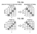
- Reversing patterns in the present invention is not limited to reversing the set states of the vertical positions of patterns within the specified range as mentioned above, so that it may mean reversing patterns with respect to a central line extending in a columnar direction of the patterns in a matrix and within a specified range.
- reversing patterns with respect to a central line extending in a columnar direction of patterns in a matrix refers to symmetrically interchanging the patterns with respect to the central line, that is, to interchanging driving patterns of the heald frames that are symmetrically positioned with respect to the central line.
- Fig. 6A shows a case for shed patterns of shed frames A to D in a specified range of from a shed step a to a shed step d.
- a central line in a columnar direction in the shed patterns is a line that is positioned between a driving pattern of the heald frame B and a driving pattern of the heald frame C.
- the central line is represented by a reference character x.
- a driving pattern of the heald frame A and a driving pattern of the heald frame D are symmetrically positioned.
- the driving pattern of the heald frame B and the driving pattern of the head frame C are symmetrically positioned.
- the driving pattern of the heald frame A and the driving pattern of the heald frame D, which are symmetrically positioned with respect to the central line x are interchanged
- the driving pattern of the heald frame B and the driving pattern of the heald frame C, which are symmetrically positioned with respect to the central line x are interchanged. Accordingly, when the driving patterns are in an interchanged state, the shed patterns before the change and the shed patterns after the change are in mirror symmetry when they are placed side by side and viewed.
- reversing patterns also means symmetrically interchanging the set driving patterns with respect to the central line in the columnar direction in the shed patterns.
- a central line in a columnar direction in shed patterns corresponds to a central line y passing through the center of a driving pattern of the heald frame C.
- driving patterns of the heald frames that is, those of the heald frames A and E and those of the heald frames B and D
- a driving pattern of the heald frame C is positioned in the center of the shed patterns within the specified range, it is in a set state that is the same as that before the reversal.
- Examples of the above-described reversed shed patterns are shed patterns that are used when weaving (back weaving) is performed so that a portion of a pattern of a front side appears at a back or reverse side of a cloth that is weaved. This will be described in more detail with reference to Figs. 7A to 7C.
- shed patterns that are used when the whole pattern at the front side appears at the front side are as represented by (a).
- shed patterns are as represented by (c).
- the shed patterns (c) are formed by the present invention.
- the regular shed patterns (a) are formed.
- a range of from the shed step no. 7 to the shed step no. 15 is specified.
- the shed patterns in the range specified above are symmetrically reversed with respect to a central line of the shed patterns.
- the reversing operation is also carried out by one operation by, for example, operating a button that is provided for the reversing operation. This causes the shed patterns to be in a set state that is indicated by (b).
- a reversing operation is carried out to reverse set states regarding vertical positions in the shed patterns in the specified range. This causes the shed patterns to be in a set state that is indicated by (c).
- the aforementioned two types of reversing operations may be executed in the reverse order.
- the reversing operations are performed by operating buttons for the respective reversing operations
- the method of executing the reversing operations is not limited thereto.
- the two types of reversing operations may be continuously carried out by operating a single operating button for forming a reversed pattern for back weaving.
- shed patterns are formed with the shed pattern setting device having, for example, the personal computer body 42 that is provided separately from the loom
- the present invention is not limited thereto.
- the shed patterns may be formed with a display device that is provided at the loom.
- the form of the shed pattern setting device is not particularly limited as along as it can form and edit shed patterns.
- shed patterns partly including reversed patterns may be formed by forming regular shed patterns, serving as base patterns, with, for example, a separately provided personal computer and performing reversing operations with a separately provided device (such as a display device provided at the loom).
- the separately provided device corresponds to the shed pattern setting device in the present invention.
Landscapes
- Engineering & Computer Science (AREA)
- Textile Engineering (AREA)
- Looms (AREA)
Applications Claiming Priority (2)
| Application Number | Priority Date | Filing Date | Title |
|---|---|---|---|
| JP2006010572 | 2006-01-19 | ||
| JP2006124554A JP5370978B2 (ja) | 2006-01-19 | 2006-04-28 | 織機における開口パターン設定装置 |
Publications (2)
| Publication Number | Publication Date |
|---|---|
| EP1811067A2 true EP1811067A2 (fr) | 2007-07-25 |
| EP1811067A3 EP1811067A3 (fr) | 2009-06-03 |
Family
ID=37946343
Family Applications (1)
| Application Number | Title | Priority Date | Filing Date |
|---|---|---|---|
| EP06026202A Withdrawn EP1811067A3 (fr) | 2006-01-19 | 2006-12-18 | Dispositif de réglage du rapport d'armure pour un métier à tisser |
Country Status (2)
| Country | Link |
|---|---|
| EP (1) | EP1811067A3 (fr) |
| JP (1) | JP5370978B2 (fr) |
Cited By (3)
| Publication number | Priority date | Publication date | Assignee | Title |
|---|---|---|---|---|
| BE1017843A3 (fr) * | 2006-04-18 | 2009-09-01 | Kabushiki Kaishi Toyota Jidoshokki | Procede et dispositif pour former un tissu via une armure envers dans un metier a tisser. |
| CN108691060A (zh) * | 2018-03-26 | 2018-10-23 | 浙江理工大学 | 一种附加纬接结双面全显色提花织物结构设计方法 |
| CN109183237A (zh) * | 2018-10-30 | 2019-01-11 | 浙江理工大学 | 一种可控行程经纱开口装置及其控制方法 |
Family Cites Families (4)
| Publication number | Priority date | Publication date | Assignee | Title |
|---|---|---|---|---|
| DE3309829A1 (de) * | 1982-03-22 | 1983-09-29 | Stäubli AG, 8810 Horgen, Zürich | Verfahren und vorrichtung zur herstellung neuer webmuster und datentraeger |
| FR2610645B1 (fr) * | 1987-02-09 | 1989-06-16 | Texel Sarl | Procede et installation pour etablir des dessins et des dessins tisses et tissu obtenu |
| JP2570909B2 (ja) * | 1991-02-18 | 1997-01-16 | 株式会社豊田自動織機製作所 | 織機のドビー装置における柄パターン制御装置 |
| JPH0594286U (ja) * | 1992-05-15 | 1993-12-24 | 楠橋紋織株式会社 | 紋織における自動柄変換装置 |
-
2006
- 2006-04-28 JP JP2006124554A patent/JP5370978B2/ja not_active Expired - Fee Related
- 2006-12-18 EP EP06026202A patent/EP1811067A3/fr not_active Withdrawn
Cited By (3)
| Publication number | Priority date | Publication date | Assignee | Title |
|---|---|---|---|---|
| BE1017843A3 (fr) * | 2006-04-18 | 2009-09-01 | Kabushiki Kaishi Toyota Jidoshokki | Procede et dispositif pour former un tissu via une armure envers dans un metier a tisser. |
| CN108691060A (zh) * | 2018-03-26 | 2018-10-23 | 浙江理工大学 | 一种附加纬接结双面全显色提花织物结构设计方法 |
| CN109183237A (zh) * | 2018-10-30 | 2019-01-11 | 浙江理工大学 | 一种可控行程经纱开口装置及其控制方法 |
Also Published As
| Publication number | Publication date |
|---|---|
| JP5370978B2 (ja) | 2013-12-18 |
| EP1811067A3 (fr) | 2009-06-03 |
| JP2007217854A (ja) | 2007-08-30 |
Similar Documents
| Publication | Publication Date | Title |
|---|---|---|
| JPH08141244A (ja) | 刺繍データ作成装置 | |
| US5239475A (en) | Data preparing apparatus | |
| US20110168070A1 (en) | Sewing machine modification tools | |
| EP1849897A1 (fr) | Dispositif de configuration des dessins d'armure pour métiers à tisser | |
| JPS58169539A (ja) | 織成意匠図およびデ−タキヤリヤを造るための方法および装置 | |
| US6321671B1 (en) | Display apparatus for a sewing machine | |
| EP1811067A2 (fr) | Dispositif de réglage du rapport d'armure pour un métier à tisser | |
| JPH10113483A (ja) | 刺繍データ編集方法並びに刺繍データ編集装置 | |
| US6944519B2 (en) | Embroidery data producing device and embroidery data producing program stored in a computer readable medium | |
| WO2007058123A1 (fr) | Dispositif et procede de creation de tricot et programme correspondant | |
| US7493867B2 (en) | Sewing machine | |
| JP2013136869A (ja) | 織機における開口パターン設定装置 | |
| KR20060116727A (ko) | 재봉기 | |
| JP2000027055A (ja) | デザイン装置 | |
| JP5013716B2 (ja) | 織機における製織関連装置に関する作動選択状態の表示設定装置 | |
| JPH0634868B2 (ja) | 自動ミシンのための縫製デ−タ作成装置 | |
| JP2025004551A (ja) | 刺繍糸の色彩設定システム | |
| JP3875765B2 (ja) | トーションレース編機の編組データ作成装置 | |
| JPH0747068B2 (ja) | 自動ミシンのための縫製デ−タ作成装置 | |
| JP3065091B2 (ja) | 自動刺しゅうミシンの文字サイズ設定方法および設定装置 | |
| JP4081832B2 (ja) | 刺繍データ処理装置及び記録媒体 | |
| JP2001017759A (ja) | 刺繍用模様データ編集装置 | |
| JP6139470B2 (ja) | 編地のデザインシステム | |
| JP2007075490A (ja) | ミシンの縫製データ作成装置 | |
| JP3061216B2 (ja) | 刺繍ブロックデータ展開装置 |
Legal Events
| Date | Code | Title | Description |
|---|---|---|---|
| PUAI | Public reference made under article 153(3) epc to a published international application that has entered the european phase |
Free format text: ORIGINAL CODE: 0009012 |
|
| AK | Designated contracting states |
Kind code of ref document: A2 Designated state(s): AT BE BG CH CY CZ DE DK EE ES FI FR GB GR HU IE IS IT LI LT LU LV MC NL PL PT RO SE SI SK TR |
|
| AX | Request for extension of the european patent |
Extension state: AL BA HR MK YU |
|
| PUAL | Search report despatched |
Free format text: ORIGINAL CODE: 0009013 |
|
| AK | Designated contracting states |
Kind code of ref document: A3 Designated state(s): AT BE BG CH CY CZ DE DK EE ES FI FR GB GR HU IE IS IT LI LT LU LV MC NL PL PT RO SE SI SK TR |
|
| AX | Request for extension of the european patent |
Extension state: AL BA HR MK RS |
|
| RIC1 | Information provided on ipc code assigned before grant |
Ipc: D03J 1/00 20060101ALI20090428BHEP Ipc: D03C 19/00 20060101AFI20090428BHEP |
|
| STAA | Information on the status of an ep patent application or granted ep patent |
Free format text: STATUS: THE APPLICATION IS DEEMED TO BE WITHDRAWN |
|
| 18D | Application deemed to be withdrawn |
Effective date: 20090701 |