EP1811092A2 - Soupage d'évacuation d'un réservoir de chasse d'eau - Google Patents
Soupage d'évacuation d'un réservoir de chasse d'eau Download PDFInfo
- Publication number
- EP1811092A2 EP1811092A2 EP06011883A EP06011883A EP1811092A2 EP 1811092 A2 EP1811092 A2 EP 1811092A2 EP 06011883 A EP06011883 A EP 06011883A EP 06011883 A EP06011883 A EP 06011883A EP 1811092 A2 EP1811092 A2 EP 1811092A2
- Authority
- EP
- European Patent Office
- Prior art keywords
- housing
- flushing valve
- float
- fitted
- valve according
- Prior art date
- Legal status (The legal status is an assumption and is not a legal conclusion. Google has not performed a legal analysis and makes no representation as to the accuracy of the status listed.)
- Withdrawn
Links
- 238000011010 flushing procedure Methods 0.000 title claims abstract description 48
- 230000007246 mechanism Effects 0.000 title claims abstract description 38
- XLYOFNOQVPJJNP-UHFFFAOYSA-N water Substances O XLYOFNOQVPJJNP-UHFFFAOYSA-N 0.000 claims abstract description 49
- 238000006073 displacement reaction Methods 0.000 claims abstract description 22
- 230000009977 dual effect Effects 0.000 claims abstract description 12
- 238000007789 sealing Methods 0.000 claims abstract description 6
- 230000004888 barrier function Effects 0.000 claims description 18
- 230000000694 effects Effects 0.000 claims description 6
- 238000013016 damping Methods 0.000 claims description 3
- 230000004913 activation Effects 0.000 description 7
- 230000000994 depressogenic effect Effects 0.000 description 4
- 239000000463 material Substances 0.000 description 4
- 230000008878 coupling Effects 0.000 description 3
- 238000010168 coupling process Methods 0.000 description 3
- 238000005859 coupling reaction Methods 0.000 description 3
- 238000003825 pressing Methods 0.000 description 3
- 230000003213 activating effect Effects 0.000 description 2
- 238000004891 communication Methods 0.000 description 2
- 238000010276 construction Methods 0.000 description 2
- 238000013461 design Methods 0.000 description 2
- 239000012530 fluid Substances 0.000 description 2
- 230000005484 gravity Effects 0.000 description 2
- 239000010808 liquid waste Substances 0.000 description 2
- 230000001105 regulatory effect Effects 0.000 description 2
- 239000002910 solid waste Substances 0.000 description 2
- 230000003247 decreasing effect Effects 0.000 description 1
- 230000000881 depressing effect Effects 0.000 description 1
- 238000011161 development Methods 0.000 description 1
- 239000013505 freshwater Substances 0.000 description 1
- 238000009434 installation Methods 0.000 description 1
- 238000004519 manufacturing process Methods 0.000 description 1
- 238000000034 method Methods 0.000 description 1
- 230000004048 modification Effects 0.000 description 1
- 238000012986 modification Methods 0.000 description 1
- 238000009877 rendering Methods 0.000 description 1
- 239000002699 waste material Substances 0.000 description 1
Images




Classifications
-
- E—FIXED CONSTRUCTIONS
- E03—WATER SUPPLY; SEWERAGE
- E03D—WATER-CLOSETS OR URINALS WITH FLUSHING DEVICES; FLUSHING VALVES THEREFOR
- E03D1/00—Water flushing devices with cisterns ; Setting up a range of flushing devices or water-closets; Combinations of several flushing devices
- E03D1/02—High-level flushing systems
- E03D1/14—Cisterns discharging variable quantities of water also cisterns with bell siphons in combination with flushing valves
-
- E—FIXED CONSTRUCTIONS
- E03—WATER SUPPLY; SEWERAGE
- E03D—WATER-CLOSETS OR URINALS WITH FLUSHING DEVICES; FLUSHING VALVES THEREFOR
- E03D5/00—Special constructions of flushing devices, e.g. closed flushing system
- E03D5/02—Special constructions of flushing devices, e.g. closed flushing system operated mechanically or hydraulically (or pneumatically) also details such as push buttons, levers and pull-card therefor
- E03D5/09—Special constructions of flushing devices, e.g. closed flushing system operated mechanically or hydraulically (or pneumatically) also details such as push buttons, levers and pull-card therefor directly by the hand
- E03D5/092—Special constructions of flushing devices, e.g. closed flushing system operated mechanically or hydraulically (or pneumatically) also details such as push buttons, levers and pull-card therefor directly by the hand the flushing element, e.g. siphon bell, being actuated through a lever
Definitions
- the present invention relates to toilet cistern flushing valve mechanisms, and particularly to dual quantity flushing valve mechanisms.
- One type of dual flush mechanisms comprises a single operating actuator, a first activation thereof opens the valve to flush the toilet bowl and a second activation is required to cease operation thereof, namely to shut water flow to the toilet bowl.
- the more popular type of dual flushing mechanisms typically comprises two different flush cycles achieved by the flush valve being adapted for two positions, whereby each cycle is activated by a separate knob or handle.
- the two positions may be at different heights with respect to the bottom of the closet's tank.
- the actuation of the knob linked to an upper valve position will produce a short or partial flush, while the actuation of a lower valve position will produce a long or full flush.
- the length of the flush cycle is a function of the height of the flush valve with respect to the closet's bottom wall. The higher the valve is from the closet's bottom wall, the smaller the volume of water that will be discharged.
- the flushing of liquid waste requires the pressing of the upper flush valve position operating knob since only a small amount of water is required for the flushing, while the flushing of solid waste requires the pressing of the knob linked to the lower flushing valve position whereby a longer flush or a larger volume of flush water is produced. In this way, water conservation is ensured.
- a toilet cistern flushing valve of compact size rendering it suitable for installation in cisterns of different configurations, e.g. substantially large or small cisterns, with long/short flush actuators of different configurations (push buttons, levers, etc.)
- the invention thus calls for a dual quantity flushing valve mechanism comprising:
- any of the following arrangements may be incorporated in the flushing mechanism:
- FIG. 1 of the drawings for understanding the construction and usage of the flushing valve in accordance with the present invention generally designated 10.
- the flushing valve 10 is disposed within a toilet cistern 12.
- the cistern 12 comprises an inlet 14 for water flow entry into the cistern 12, a float control mechanism 15 coupled to the inlet 14, for regulating water flow into the cistern 12.
- An outlet 16 is disposed at a bottom portion of the cistern 12 and is coupled to a toilet bowl (not shown).
- An operation mechanism 18 is fitted on the top of the cistern 12 and is articulated to the flushing valve 10 for operation thereof.
- the flushing valve 10 is secured to the outlet 16 via a base coupler 20.
- the base coupler 20 has slots 21 formed therein, through which the base coupler 20 is in fluid communication with the cistern 12.
- the flushing valve 10 comprises an annular plug 22, fitted with an annular seal 23, extending within the base coupler 20, adapted for sealing water passage into the outlet 16, whenever the flushing valve is in its closed position.
- the valve 10 comprises a substantially cylindrical housing 32 (which in the drawings is partially concealed to facilitate viewing of the internal components therein).
- the housing 32 comprises an open top portion 34, and is formed with a large slot 38, a small slot 40 and several notches 42 disposed adjacent to the top portion 34, adapted for fastening different covers thereto, as will be discussed hereinafter.
- the housing 32 further comprises a bottom portion 43, formed with a downwardly extending rim 44 for detachably connecting to the base coupler 20, and a propulsion inlet 48 formed therein (elaborated in connection with Fig. 7).
- the large slot 38 extends from about slightly higher than the middle of the housing 32 to the top portion 34.
- the small slot 40 is disposed diametrically opposite to the large slot 38, extending upwardly from about the middle of the housing 32 a length, for example. However, position of the small slot 40 may differ with respect to the position of the large slot 38.
- the housing 32 is detachably secured to the base coupler 20 by snap coupling, however it may be secured in other ways, e.g., by threaded coupling, bayonet coupling, etc., and typically the arrangement is such that the housing 32 may be rotatably fixed with respect to the base coupler 20.
- the base coupler 20 has an externally threaded tubular bottom portion 50 and is fitted for projecting through an opening formed at a bottom wall of the cistern 12 and is connectable by said threading to outlet pipe 16 which as discussed hereinabove in connection with in Fig. 1, is coupled in turn to a toilet bowl (typically via an intermediate pipe segment, not shown).
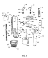
- a non-linear overflow pipe and float guide 62 disposed partially within the housing 32, comprises a bottom portion of the pipe 64 being vertically oriented, disposed coaxially within the housing 32 and being in fluid communication with the tubular bottom portion 50, an intermediate portion of the pipe 66, disposed above the first portion 64, being slanted and protruding upwardly from the housing 32 via the large slot 38 therein, and a top portion of the pipe 68, disposed above the intermediate portion 66, being substantially vertically oriented with an open upper end 69, and accommodating a telescopic extension tube section 70 (Fig. 3) with an open top end 71, axially displaceable with respect to the top portion of the pipe 68.
- the height of the top end 71 determines an overflow level of the cistern 12, namely the top end 71 determines the maximal water level within the cistern 12 so that in case of a system miscalibration or failure, in which the water level rises above the height of top end 71, the water may drain through the pipe 62, and hence the tubular bottom portion 50 into the outlet 16 (Fig. 1).
- the bottom portion of the pipe 64 may be integrally formed with the annular plug 22 described in Fig. 1, supporting the rubber seal disc 23 so as to more effectively seal an axial aperture 52 of the base coupler 20 (Fig. 2).
- the plug 22 may be fitted on a lowermost end of the bottom portion of the pipe 64.
- the bottom portion 64 of the overflow pipe 62 is further formed with a plurality of laterally projecting wings 72, and a lateral flange 75 formed integrally therewith, to be described hereinafter.
- the intermediate portion 66 of the pipe 62 is formed with two laterally extending arms 74, with their extreme edges 78 oriented away from each other (substantially radial), so that the extreme ends 78 are slidingly received within internal axial grooves 76 that extend along an internal wall portion of the housing 32, whereby the overflow pipe 62 is adapted for axial displacement only within the housing 32.
- a support member 80 vertically displaceable outside the housing 32, is attached to the first flange 75.
- the support member 80 is in the form of a thin connecting bar, with one surface having a toothed-rack like appearance 84 and another surface further comprising a second flange 82 formed thereon.
- the second flange 82 is articulated to the first flange 75 and laterally projects through slot 40 formed in the housing 32.
- the arrangement is such that vertical displacement of the overflow pipe 62 entails corresponding vertical displacement of the support member 80 and vice versa.
- the support member 80 has mounted thereon an external float 88 (referred to as a "half flush float", as it is associated with flushing only a partial volume of the cistern 12 as will become apparent hereinafter).
- the external float 88 may have a buoyant material inserted therein, e.g. foamed material, a water tight space, etc.
- the external float 88 is slidingly displaceable over a portion of the toothed rack-like surface 84 of the support member 80 and is fitted with a clasp 90 formed in turn with a projection 91, fitted for engaging with the teeth of the toothed surface 84 so as to calibrate the vertical level of the external float 88.
- the arrangement is such that the external float 88 is stationary with respect to the support member 80, i.e. with respect to the pipe 62, and is articulated displaceable therewith.
- the button operated flushing valve 10 comprises a top cover 92 articulated to the top portion of the housing 32, e.g. by snap-type engagement with notches 42 of the housing 32.
- the cover 92 comprises in turn a chamber 100 accommodating two push buttons, namely a full flush button 96 and a half-flush button 95, each having an upper pressing surface 104 and an elongated vertical stem 97 and 98, respectively, integrally formed therewith and extending downwards through respective openings formed in a bottom wall 102 of the top cover 92.
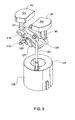
- the full flush button 96 and the half-flush button 95 are each fitted with a coiled spring 99 (Fig.3) mounted on the respective stem, disposed between the upper surface 104 and the bottom wall 102 of the top cover 92, for biasing the buttons into their non-depressed position (in Figs. 2 and 5 the full flush button 96 is shown in its depressed position and the half-flush button 95 in its elevated position, and in Fig. 6 vice versa).
- An annular rim 108 of the top cover 92 further comprises a guide member 112, adapted to slidingly receive and support the support member 80.
- the elongated vertical stems 97 and 98 are each in contact with a lever system 114, completely disposed within the housing 32, at a top portion thereof, above the intermediate portion 66 of the pipe 62 (Fig. 2).
- the lever system 114 comprises a shaft 116, oriented horizontally, inserted in two notches 47 (one of which is seen in Fig. 3) in the housing 32 (Figs. 1 to 3) such that translational movement is prevented but not rotational movement.
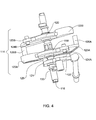
- first rocker lever 118 Mounted on the shaft 116 in a freely rotatable manner there is a first rocker lever 118, a second rocker lever 120 and a barrier 121.
- the center of gravity of the first rocker lever 118 and second rocker lever 120 is such that they normally retain a ready state, namely extend at a substantially horizontal position.
- Both the first rocker lever 118 and the second rocker lever 120 are physically similar though oriented in opposite directions, and each comprises a first end 122A, 122B respectively, adapted for contact with the vertical stem 97 and 98, respectively.
- the first ends 122A and 122B are arced so as to enable continuous and smooth contact with a bottom end of the respective vertical stem 97 and 98.
- a second end 123A and 123B of each rocker is fitted with a first lateral projection 124A and 124B, respectively, and a second lateral protrusion 126A and 126B, to be further elaborated on hereinafter.
- first rocker lever 118 and the barrier 121 are articulated to one another by a lateral projection 125, so that rotational movement of the first lever 118 entails the barrier 121 to rotationally displace in the same sense.
- the barrier 121 is formed with an arresting arm portion 127, extending shorter than the second end 123A of the first rocker lever 118, the reason for which will become apparent hereinafter.
- each second lateral protrusion 126A and 126B is positioned under an extending arm 74 of the overflow pipe 62.
- the button valve 10 further comprises a substantially cylindrical internal float 128 concentrically mounted inside the housing 32, normally disposed at the bottom portion 43 thereof and further being slidingly disposed over the bottom portion 64 of the overflow pipe 62.
- a substantially cylindrical internal float 128 concentrically mounted inside the housing 32, normally disposed at the bottom portion 43 thereof and further being slidingly disposed over the bottom portion 64 of the overflow pipe 62.
- axial displacement of the internal float 128 in an upwards direction is restricted by the wings 72 of the overflow pipe 62 adapted for engaging a top surface 129 of the internal float 128.
- the float 128 may accommodate buoyant material (e.g. foamed material).
- buoyant material e.g. foamed material
- the internal float 128 is free to move in the axial direction when not restrained by the wings 72.
- the wings 72 biased downwards by the weight of the pipe 62, serve to ensure the internal float 128 normally remains in the lowest possible position within the housing 32, sealing the outlet 16 (Fig. 1) from the cistern 12 (Fig. 1).
- the rod 132 is disposed under the barrier 121 such that when the barrier 121 is rotated to a substantially horizontal orientation (Figs. 4 and 6), the arresting arm portion 127 of the barrier 121 is positioned directly above the rod 132, preventing further upwards displacement of the rod 132 and the articulated internal float 128. Additionally, if the barrier 121 is rotated to a substantially vertical orientation, as seen in Figs. 1, 2 and 5, then there is no portion of the barrier 121 above the rod 132, thus the of the rod 132 and the articulated internal float 128 are free to axially displace upwardly until abutment of the internal float 128 with wings 72. It is also noteworthy to mention in the normal position the barrier 121 is designed to be in its substantially vertical orientation.
- the normal state of the cistern 12 being at least partially filled with water (not shown), which enters the cistern 12 via the inlet 14.
- the water level in the cistern 12 is calibrated to a chosen height by means of the control mechanism 15 which is adapted to detect when the water in the cistern 12 reaches at least a specified level and regulate the flow through the inlet 14 accordingly.
- the flushing valve 10 being at least partially submerged in the water, having lateral slots allowing water to access the base coupler 20.
- the flushing valve 10 may raise the plug 22 allowing the water in the cistern 12 to drain into the outlet 16.
- the water in the outlet 16 may be directed into a toilet bowl (not shown) forcing waste (not shown) into a sewer (not shown).
- a full flush button 96 is depressed (Figs. 1, 2 and 5).
- the coiled spring 99 is thereby compressed and the relevant stem 98 descends into the housing 32 applying a downwards force on the first end 122B of the second rocker lever 120, causing it to pivot about shaft 116.
- the recoil of the spring 99 causes the button 96 to immediately revert to it's elevated position (Fig. 6) upon stopping a force applied thereto.
- the rotation of the second lever 120 causes the second lateral protrusion 126B thereof to elevate the corresponding extending arm 74 of the overflow pipe 62.
- the elevation of the pipe 62 entails raising the external float 88 (owing to buoyancy forces), and lifting the annular plug 22, facilitating full drainage of the cistern 12.
- the drainage causes the water level in the cistern 12 to drop below the calibrated water level.
- the upwards motion of the plug 22 forces water into the propulsion inlet 48, thereby applying additional force propelling the internal float 128 in an upwards direction.
- the upwards motion of the internal float 128 is halted when the its top surface engages the wings 72, of the already elevated pipe 62, the upwards motion of which is halted when the annular plug 22 encounters the bottom base of the housing 32.
- the pipe 62 and connected components begin to descend, due to gravitational forces, to their original, downward positions.
- the downwards motion of the pipe 62 is retarded by the external float 88 and the internal float 128 thereby increasing drainage time.
- the rate of descent is decreased when the buoyant external float 88 contacts the reducing water level, the force of the water on the external float 88 being in the upward direction. Additionally, the descent of the pipe 62 is further retarded by the slow descent of the internal float 128.
- the internal float 128 is forced downwards by the wings 72 of the pipe 62, which are propelled by the weight of the pipe 62, however, as the water beneath the internal float 128 must exit compartment 45 of the housing 32 via the small propulsion outlet 48 creating a damping effect and thereby impeding the descent of the internal float 128.
- propulsion outlet 48 may be of controllable section area, e.g. by a manual lever 135 pivotally secured at 131 to the bottom wall of the compartment 125, governing the section are of the outlet, to thereby govern the descending speed of the overflow pipe 62.
- Fig. 6 there is illustrated the lever system 114 with the half-flush button 95 depressed.
- the operation of the button valve 10 is substantially similar to that described in the previous example, however with the following differences.
- the depression of the half-flush button 95 causes rotation of the second rocker lever 120 and therefore a corresponding pivotal displacement of the articulated barrier 121.
- the arresting arm portion 127 of the barrier 121 is thereby rotated to a substantially horizontal orientation.
- Pivotal displacement of barrier 121 is restricted by a projection 133 extending from the shaft 118.
- the upward motion of the internal float 128 is halted when the rod 132 impacts the arresting arm portion 127 of the barrier 121.
- the distance traveled by the internal float 128 is significantly less than in the previous example, associated with a full flush mode, and hence the retardation effect caused thereby will be significantly shorter. Thus there is a shorter drainage period causing the desired half-flush effect.
- the elevation of the external float 88 in fact governs the amount of water to be flushed in a 'half flush' procedure.
- Fig. 8 is directed to a modification of the invention, illustrating the activating mechanism generally referred to at 140, wherein rather than a press button valve there is provided a pull-lever valve.
- the pull-lever valve 140 differs from the button valve 10 by the replacement of the cover 92 with an alternate cover 142 adapted for pull-levers 144A and 144B, associated with the half-flush and full-flush rocker levers 118 and 120, respectively.
- Each pull-lever 144A and 144B is mounted on the relevant lateral protrusions 124A and 124B, respectively, and protrudes from the housing 32 upwardly through the alternate cover 142.
- each pull-lever 144 has a handle 146 at the upper end thereof. These handles are articulated to lever operators typically fitted on a front wall of a cistern (not shown).
- the operation of the button valve 10 is identical to that of the pull-lever valve 140 except that the respective second end 123A and 123B of either the first lever 118 or second lever 120 is pulled in order to create a desired rotational motion and the following chain of effects that are caused.
Landscapes
- Engineering & Computer Science (AREA)
- Health & Medical Sciences (AREA)
- Life Sciences & Earth Sciences (AREA)
- Hydrology & Water Resources (AREA)
- Public Health (AREA)
- Water Supply & Treatment (AREA)
- Mechanical Engineering (AREA)
- Aviation & Aerospace Engineering (AREA)
- Sanitary Device For Flush Toilet (AREA)
Applications Claiming Priority (1)
| Application Number | Priority Date | Filing Date | Title |
|---|---|---|---|
| IL173213A IL173213A0 (en) | 2006-01-18 | 2006-01-18 | Flushing valve mechanism |
Publications (1)
| Publication Number | Publication Date |
|---|---|
| EP1811092A2 true EP1811092A2 (fr) | 2007-07-25 |
Family
ID=37965275
Family Applications (1)
| Application Number | Title | Priority Date | Filing Date |
|---|---|---|---|
| EP06011883A Withdrawn EP1811092A2 (fr) | 2006-01-18 | 2006-06-08 | Soupage d'évacuation d'un réservoir de chasse d'eau |
Country Status (3)
| Country | Link |
|---|---|
| US (1) | US20070163034A1 (fr) |
| EP (1) | EP1811092A2 (fr) |
| IL (1) | IL173213A0 (fr) |
Cited By (1)
| Publication number | Priority date | Publication date | Assignee | Title |
|---|---|---|---|---|
| CN108222154A (zh) * | 2017-06-24 | 2018-06-29 | 郭文平 | 一种设置前后翻转覆盖件的冲厕水箱 |
Families Citing this family (13)
| Publication number | Priority date | Publication date | Assignee | Title |
|---|---|---|---|---|
| AU319921S (en) * | 2008-02-28 | 2008-06-11 | Caroma Industries Ltd | A cistern support bracket |
| USD638108S1 (en) * | 2008-08-25 | 2011-05-17 | Caroma Industries Limited | Cistern support bracket |
| CA2695274C (fr) | 2009-03-02 | 2017-02-14 | Mjsi, Inc. | Adaptation de robinet de fond de cuve pour capacite double chasse |
| US9447570B1 (en) | 2010-10-15 | 2016-09-20 | Danco, Inc. | Dual flush handle control |
| US9803348B1 (en) | 2010-11-30 | 2017-10-31 | Danco, Inc. | Electrically controlled flush |
| CN102418373B (zh) * | 2010-12-11 | 2013-11-06 | 李飞宇 | 一种双排阀 |
| US9267275B2 (en) | 2011-11-22 | 2016-02-23 | Danco, Inc. | Dual flush handle control |
| US9228333B1 (en) * | 2011-11-22 | 2016-01-05 | Danco, Inc. | Dual flush handle control |
| US9834918B2 (en) * | 2012-03-13 | 2017-12-05 | Delta Faucet Company | Toilet with overflow protection |
| CA2928755C (fr) * | 2013-11-13 | 2017-12-12 | Lab (Xiamen) Sanitary Fittings Inc | Appareil de debut de tube de cur interne pour clapet double de purge d'eau |
| WO2017201642A1 (fr) * | 2016-05-23 | 2017-11-30 | 厦门立业卫浴工业有限公司 | Dispositif de fixation pour cylindre central interne de robinet de chasse |
| CN108166583A (zh) * | 2017-11-20 | 2018-06-15 | 广东恒洁卫浴有限公司 | 延时加水进水杆 |
| CN109881747A (zh) * | 2019-04-08 | 2019-06-14 | 广东安百利卫浴科技有限公司 | 一种中心力平衡的排水阀提拉机构 |
Family Cites Families (3)
| Publication number | Priority date | Publication date | Assignee | Title |
|---|---|---|---|---|
| SE9404138L (sv) * | 1994-11-29 | 1995-10-09 | Ifoe Sanitaer Ab | Klosettarmatur för vattenklosetter |
| US6510866B2 (en) * | 2001-03-26 | 2003-01-28 | Wdi International, Inc. | Ball cock assembly, float assembly for same, and method of controlling liquid level in a tank |
| US6666228B1 (en) * | 2003-06-12 | 2003-12-23 | Feiyu Li | Ball cock assembly |
-
2006
- 2006-01-18 IL IL173213A patent/IL173213A0/en unknown
- 2006-06-08 EP EP06011883A patent/EP1811092A2/fr not_active Withdrawn
-
2007
- 2007-01-17 US US11/654,028 patent/US20070163034A1/en not_active Abandoned
Cited By (1)
| Publication number | Priority date | Publication date | Assignee | Title |
|---|---|---|---|---|
| CN108222154A (zh) * | 2017-06-24 | 2018-06-29 | 郭文平 | 一种设置前后翻转覆盖件的冲厕水箱 |
Also Published As
| Publication number | Publication date |
|---|---|
| US20070163034A1 (en) | 2007-07-19 |
| IL173213A0 (en) | 2006-06-11 |
Similar Documents
| Publication | Publication Date | Title |
|---|---|---|
| US20070163034A1 (en) | Flushing valve mechanism | |
| US4651359A (en) | Dual mode flush valve assembly | |
| AU746540B2 (en) | Discharge valve for flushing cisterns | |
| US6510866B2 (en) | Ball cock assembly, float assembly for same, and method of controlling liquid level in a tank | |
| US6637042B2 (en) | Toilet valve assembly | |
| US5524297A (en) | Two-level flush valve | |
| US20050217012A1 (en) | Dual Flush Water Saving Toilet System | |
| WO2009066096A1 (fr) | W.c. économique en eau | |
| WO2007059398A2 (fr) | Mecanisme de toilette a deux chasses d'eau | |
| WO2007139371A1 (fr) | Appareil de vanne | |
| JPH08302781A (ja) | 節水機能を有するトイレ排水装置 | |
| JPH08302782A (ja) | 節水機能を有するトイレ排水装置 | |
| US6658673B2 (en) | Toilet valve assembly | |
| US5216761A (en) | Flush volume controls for toilets | |
| GB2453439A (en) | Flushing valve | |
| US8117687B2 (en) | Diverter valve with minimum bias forces | |
| GB2402136A (en) | Water saving device for toilet | |
| US20050193483A1 (en) | Adjustable toilet valve assembly | |
| US4082110A (en) | Water level control for toilet having vertical float | |
| US20020095719A1 (en) | Toilet valve assembly | |
| US4086667A (en) | Flush control device for conserving water | |
| CA2174587C (fr) | Dispositif de chasse economiseur d'eau | |
| KR102186897B1 (ko) | 변기용수배출장치 | |
| US5291620A (en) | Push button toilet flush mechanism | |
| US5440765A (en) | Revised automatic water shut off for stuck open flush valves in toilet water tanks |
Legal Events
| Date | Code | Title | Description |
|---|---|---|---|
| PUAI | Public reference made under article 153(3) epc to a published international application that has entered the european phase |
Free format text: ORIGINAL CODE: 0009012 |
|
| AK | Designated contracting states |
Kind code of ref document: A2 Designated state(s): AT BE BG CH CY CZ DE DK EE ES FI FR GB GR HU IE IS IT LI LT LU LV MC NL PL PT RO SE SI SK TR |
|
| AX | Request for extension of the european patent |
Extension state: AL BA HR MK YU |
|
| STAA | Information on the status of an ep patent application or granted ep patent |
Free format text: STATUS: THE APPLICATION IS DEEMED TO BE WITHDRAWN |
|
| 18D | Application deemed to be withdrawn |
Effective date: 20100105 |