EP1811146A1 - Appareil d évaluation d un agent réducteur de liquide - Google Patents
Appareil d évaluation d un agent réducteur de liquide Download PDFInfo
- Publication number
- EP1811146A1 EP1811146A1 EP05785706A EP05785706A EP1811146A1 EP 1811146 A1 EP1811146 A1 EP 1811146A1 EP 05785706 A EP05785706 A EP 05785706A EP 05785706 A EP05785706 A EP 05785706A EP 1811146 A1 EP1811146 A1 EP 1811146A1
- Authority
- EP
- European Patent Office
- Prior art keywords
- reducing agent
- liquid reducing
- concentration
- vehicle
- aqueous solution
- Prior art date
- Legal status (The legal status is an assumption and is not a legal conclusion. Google has not performed a legal analysis and makes no representation as to the accuracy of the status listed.)
- Granted
Links
Images


Classifications
-
- F—MECHANICAL ENGINEERING; LIGHTING; HEATING; WEAPONS; BLASTING
- F01—MACHINES OR ENGINES IN GENERAL; ENGINE PLANTS IN GENERAL; STEAM ENGINES
- F01N—GAS-FLOW SILENCERS OR EXHAUST APPARATUS FOR MACHINES OR ENGINES IN GENERAL; GAS-FLOW SILENCERS OR EXHAUST APPARATUS FOR INTERNAL-COMBUSTION ENGINES
- F01N3/00—Exhaust or silencing apparatus having means for purifying, rendering innocuous, or otherwise treating exhaust
- F01N3/08—Exhaust or silencing apparatus having means for purifying, rendering innocuous, or otherwise treating exhaust for rendering innocuous
- F01N3/10—Exhaust or silencing apparatus having means for purifying, rendering innocuous, or otherwise treating exhaust for rendering innocuous by thermal or catalytic conversion of noxious components of exhaust
- F01N3/18—Exhaust or silencing apparatus having means for purifying, rendering innocuous, or otherwise treating exhaust for rendering innocuous by thermal or catalytic conversion of noxious components of exhaust characterised by methods of operation; Control
- F01N3/20—Exhaust or silencing apparatus having means for purifying, rendering innocuous, or otherwise treating exhaust for rendering innocuous by thermal or catalytic conversion of noxious components of exhaust characterised by methods of operation; Control specially adapted for catalytic conversion
- F01N3/206—Adding periodically or continuously substances to exhaust gases for promoting purification, e.g. catalytic material in liquid form, NOx reducing agents
- F01N3/208—Control of selective catalytic reduction [SCR], e.g. by adjusting the dosing of reducing agent
-
- G—PHYSICS
- G01—MEASURING; TESTING
- G01N—INVESTIGATING OR ANALYSING MATERIALS BY DETERMINING THEIR CHEMICAL OR PHYSICAL PROPERTIES
- G01N25/00—Investigating or analyzing materials by the use of thermal means
- G01N25/18—Investigating or analyzing materials by the use of thermal means by investigating thermal conductivity
-
- F—MECHANICAL ENGINEERING; LIGHTING; HEATING; WEAPONS; BLASTING
- F01—MACHINES OR ENGINES IN GENERAL; ENGINE PLANTS IN GENERAL; STEAM ENGINES
- F01N—GAS-FLOW SILENCERS OR EXHAUST APPARATUS FOR MACHINES OR ENGINES IN GENERAL; GAS-FLOW SILENCERS OR EXHAUST APPARATUS FOR INTERNAL-COMBUSTION ENGINES
- F01N2550/00—Monitoring or diagnosing the deterioration of exhaust systems
-
- F—MECHANICAL ENGINEERING; LIGHTING; HEATING; WEAPONS; BLASTING
- F01—MACHINES OR ENGINES IN GENERAL; ENGINE PLANTS IN GENERAL; STEAM ENGINES
- F01N—GAS-FLOW SILENCERS OR EXHAUST APPARATUS FOR MACHINES OR ENGINES IN GENERAL; GAS-FLOW SILENCERS OR EXHAUST APPARATUS FOR INTERNAL-COMBUSTION ENGINES
- F01N2560/00—Exhaust systems with means for detecting or measuring exhaust gas components or characteristics
- F01N2560/12—Other sensor principles, e.g. using electro conductivity of substrate or radio frequency
-
- F—MECHANICAL ENGINEERING; LIGHTING; HEATING; WEAPONS; BLASTING
- F01—MACHINES OR ENGINES IN GENERAL; ENGINE PLANTS IN GENERAL; STEAM ENGINES
- F01N—GAS-FLOW SILENCERS OR EXHAUST APPARATUS FOR MACHINES OR ENGINES IN GENERAL; GAS-FLOW SILENCERS OR EXHAUST APPARATUS FOR INTERNAL-COMBUSTION ENGINES
- F01N2610/00—Adding substances to exhaust gases
- F01N2610/02—Adding substances to exhaust gases the substance being ammonia or urea
-
- F—MECHANICAL ENGINEERING; LIGHTING; HEATING; WEAPONS; BLASTING
- F01—MACHINES OR ENGINES IN GENERAL; ENGINE PLANTS IN GENERAL; STEAM ENGINES
- F01N—GAS-FLOW SILENCERS OR EXHAUST APPARATUS FOR MACHINES OR ENGINES IN GENERAL; GAS-FLOW SILENCERS OR EXHAUST APPARATUS FOR INTERNAL-COMBUSTION ENGINES
- F01N2610/00—Adding substances to exhaust gases
- F01N2610/10—Adding substances to exhaust gases the substance being heated, e.g. by heating tank or supply line of the added substance
-
- F—MECHANICAL ENGINEERING; LIGHTING; HEATING; WEAPONS; BLASTING
- F01—MACHINES OR ENGINES IN GENERAL; ENGINE PLANTS IN GENERAL; STEAM ENGINES
- F01N—GAS-FLOW SILENCERS OR EXHAUST APPARATUS FOR MACHINES OR ENGINES IN GENERAL; GAS-FLOW SILENCERS OR EXHAUST APPARATUS FOR INTERNAL-COMBUSTION ENGINES
- F01N2900/00—Details of electrical control or of the monitoring of the exhaust gas treating apparatus
- F01N2900/04—Methods of control or diagnosing
- F01N2900/0421—Methods of control or diagnosing using an increment counter when a predetermined event occurs
-
- F—MECHANICAL ENGINEERING; LIGHTING; HEATING; WEAPONS; BLASTING
- F01—MACHINES OR ENGINES IN GENERAL; ENGINE PLANTS IN GENERAL; STEAM ENGINES
- F01N—GAS-FLOW SILENCERS OR EXHAUST APPARATUS FOR MACHINES OR ENGINES IN GENERAL; GAS-FLOW SILENCERS OR EXHAUST APPARATUS FOR INTERNAL-COMBUSTION ENGINES
- F01N2900/00—Details of electrical control or of the monitoring of the exhaust gas treating apparatus
- F01N2900/04—Methods of control or diagnosing
- F01N2900/0422—Methods of control or diagnosing measuring the elapsed time
-
- F—MECHANICAL ENGINEERING; LIGHTING; HEATING; WEAPONS; BLASTING
- F01—MACHINES OR ENGINES IN GENERAL; ENGINE PLANTS IN GENERAL; STEAM ENGINES
- F01N—GAS-FLOW SILENCERS OR EXHAUST APPARATUS FOR MACHINES OR ENGINES IN GENERAL; GAS-FLOW SILENCERS OR EXHAUST APPARATUS FOR INTERNAL-COMBUSTION ENGINES
- F01N2900/00—Details of electrical control or of the monitoring of the exhaust gas treating apparatus
- F01N2900/06—Parameters used for exhaust control or diagnosing
- F01N2900/18—Parameters used for exhaust control or diagnosing said parameters being related to the system for adding a substance into the exhaust
- F01N2900/1806—Properties of reducing agent or dosing system
- F01N2900/1814—Tank level
-
- F—MECHANICAL ENGINEERING; LIGHTING; HEATING; WEAPONS; BLASTING
- F01—MACHINES OR ENGINES IN GENERAL; ENGINE PLANTS IN GENERAL; STEAM ENGINES
- F01N—GAS-FLOW SILENCERS OR EXHAUST APPARATUS FOR MACHINES OR ENGINES IN GENERAL; GAS-FLOW SILENCERS OR EXHAUST APPARATUS FOR INTERNAL-COMBUSTION ENGINES
- F01N2900/00—Details of electrical control or of the monitoring of the exhaust gas treating apparatus
- F01N2900/06—Parameters used for exhaust control or diagnosing
- F01N2900/18—Parameters used for exhaust control or diagnosing said parameters being related to the system for adding a substance into the exhaust
- F01N2900/1806—Properties of reducing agent or dosing system
- F01N2900/1818—Concentration of the reducing agent
-
- Y—GENERAL TAGGING OF NEW TECHNOLOGICAL DEVELOPMENTS; GENERAL TAGGING OF CROSS-SECTIONAL TECHNOLOGIES SPANNING OVER SEVERAL SECTIONS OF THE IPC; TECHNICAL SUBJECTS COVERED BY FORMER USPC CROSS-REFERENCE ART COLLECTIONS [XRACs] AND DIGESTS
- Y02—TECHNOLOGIES OR APPLICATIONS FOR MITIGATION OR ADAPTATION AGAINST CLIMATE CHANGE
- Y02A—TECHNOLOGIES FOR ADAPTATION TO CLIMATE CHANGE
- Y02A50/00—TECHNOLOGIES FOR ADAPTATION TO CLIMATE CHANGE in human health protection, e.g. against extreme weather
- Y02A50/20—Air quality improvement or preservation, e.g. vehicle emission control or emission reduction by using catalytic converters
-
- Y—GENERAL TAGGING OF NEW TECHNOLOGICAL DEVELOPMENTS; GENERAL TAGGING OF CROSS-SECTIONAL TECHNOLOGIES SPANNING OVER SEVERAL SECTIONS OF THE IPC; TECHNICAL SUBJECTS COVERED BY FORMER USPC CROSS-REFERENCE ART COLLECTIONS [XRACs] AND DIGESTS
- Y02—TECHNOLOGIES OR APPLICATIONS FOR MITIGATION OR ADAPTATION AGAINST CLIMATE CHANGE
- Y02T—CLIMATE CHANGE MITIGATION TECHNOLOGIES RELATED TO TRANSPORTATION
- Y02T10/00—Road transport of goods or passengers
- Y02T10/10—Internal combustion engine [ICE] based vehicles
- Y02T10/12—Improving ICE efficiencies
Definitions
- the present invention relates to a technique enabling it to always discriminate one from such three conditions that there is no remainder of a liquid reducing agent, there remains a solution of a different kind from a liquid reducing agent, or there remains a normal liquid reducing agent by the use of a sensor configured to output a signal in relation to concentration of a liquid reducing agent on the basis of a characteristic of heat transmission between two points apart from each other.
- Patent document 1 discloses an exhaust gas purifying apparatus.
- a liquid reducing agent of a necessary amount depending on the engine operating conditions is injected into an exhaust gas moving on an upstream side of a reduction catalytic converter, which is disposed in an engine exhaust system to make a catalytic reduction reaction between NO x in the exhaust gas and the liquid reducing agent, thereby converting NO x to harmless components.
- Patent Document 1 Japanese Unexamined Patent Publication No. 2000-27627
- an object of the present invention is to provide a liquid reducing agent discriminating apparatus capable of always discriminating one from such three conditions that there is no remainder of liquid reducing agent, there remains a different kind of liquid or solution, and there is a liquid reducing agent that is normal by using the fact that, as long as the liquid reducing agent is normal one, even when convection occurs, it is extremely rare that a sensor output deviates from a predetermined range a number of times in a row.
- the present invention provides a liquid reducing agent discriminating apparatus comprising: a sensor disposed in a storage tank capable of storing a liquid reducing agent and configured to output a signal in relation to concentration of the liquid reducing agent on the basis of a characteristic of heat transmission between two points apart from each other; and a control unit having therein a computer, wherein the control unit outputs a measurement trigger at an every predetermined time after start of an engine, calculates concentration of the liquid reducing agent on the basis of the signal from the sensor upon outputting of the measurement trigger, counts each of first number of times when the concentration successively becomes equal to or higher than a predetermined upper limit threshold and second number of times when the concentration successively becomes equal to or lower than a predetermined lower limit threshold, determines that there is no remainder of liquid reducing agent when the first number of times becomes equal to or larger than a predetermined value, and, determines that there remains a solution of a different kind from the liquid reducing agent when the second number of times becomes equal to or larger than the predetermined value.
- the liquid reducing agent discriminating apparatus of the invention uses such a true fact that, as long as the liquid reducing agent is normal solution, even when convection occurs, it is extremely rare that a sensor output deviates from a predetermined range a number of times in a row.
- the liquid reducing agent discriminating apparatus determines that there is no remainder of liquid urea aqueous or there remains a solution different kind from the liquid urea aqueous. Consequently, irrespective of the state that a vehicle is left to be in, it can be always discriminated that there is no remainder of liquid reducing agent or there remains a solution different in its kind from the liquid reducing agent.
- FIG. 1 shows a general configuration of an exhaust gas purifying system provided with a liquid reducing agent discriminating apparatus according to the present invention
- an exhaust gas of an engine 10 is exhausted from an exhaust manifold 12 to atmosphere through an exhaust pipe 16 in which an NO x reduction catalytic converter 14 is disposed.
- an exhaust pipe 16 in which an NO x reduction catalytic converter 14 is disposed.
- three catalytic converters of an oxidation catalytic converter of nitric oxide (NO), an NO x reduction catalytic converter, and a slip ammonia oxidation catalytic converter are disposed.
- a temperature sensor, an oxygen sensor, and the like are disposed before and after the three catalytic converters, thereby constructing an exhaust system (the details are not shown).
- a liquid reducing agent stored in a storage tank 18 is injected together with air through a reducing agent supplying device 20 and an injection nozzle 22.
- a urea aqueous solution is used as the liquid reducing agent in the embodiment, an ammonia aqueous solution, or diesel oil, petroleum, gasoline, in which hydrocarbon is included as a main component, or the like may be used.
- the urea aqueous solution is a solution in which solid or powder urea is dissolved.
- the urea aqueous solution is sucked from a suction port 24 opened in a lower position near the bottom of the storage tank 18 and is supplied to the reducing agent supplying device 20 through a supply pipe 26.
- An excess, which does not contribute to injection, of the urea aqueous solution supplied to the reducing agent supplying device 20 passes through a return pipe 28 and is returned to the storage tank 18 from a return port 30 opened in an upper position in the storage tank 18.
- the urea aqueous solution injected on the exhaust upstream of the NO x reduction catalytic converter 14 is hydrolyzed with exhaust heat and steam in the exhaust gas, so that ammonia is easily generated. It is known that the generated ammonia reacts with NO x in the exhaust in the NO x reduction catalytic converter 14 and is converted to water and harmless gas.
- a sensor 32 that is configured to output a signal related to the concentration of the urea aqueous solution is attached.
- a base unit 32A having therein a circuit board is secured to the ceiling of the storage tank 18, and a detecting unit 32B is hung down from the base unit 32A toward the bottom of the storage tank 18.
- a heater A and a temperature sensor B are disposed in two positions apart from each other, which are located within the storage tank.
- a signal related to concentration of the urea aqueous solution is outputted on the basis of the characteristic of heat transmitted to the temperature sensor B.
- the temperature in the temperature sensor B gradually increases with the characteristic according to thermal conductivity of the urea aqueous solution.
- the concentration of the urea aqueous solution can be indirectly detected according to the temperature rise characteristic when the heater A is stopped, that is, the difference between the initial temperature and the peak temperature in the temperature sensor B.
- the temperature in the temperature sensor B gradually drops to the temperature before the heater operates by taking time t 2 . Consequently, the concentration of the urea aqueous solution can be detected every predetermined time (t 1 +t 2 ).
- the sensor 32 a sensor manufactured and sold by Mitsui Mining & Smelting Co., Ltd. is known.
- An output signal of the sensor 32 is inputted to a control unit 34 having therein a computer.
- an engine rotating speed signal, an ignition switch signal, a vehicle speed signal, and the like are inputted from an engine control unit 36 for performing various controls on the engine 10 via a CAN (Controller Area Network) or the like.
- a control program stored in a ROM (Read Only Memory) as shown in FIG. 3, a measurement trigger outputting unit 34A, a vehicle state determining unit 34B, a concentration calculating unit 34C, a counting unit 34D, and a reducing agent determining unit 34E are realized.
- the engine control unit 34 has the functions of an engine rotating speed detector and a vehicle speed detector. Alternatively, the engine rotating speed and the vehicle speed may be separately detected by known sensors.
- the measurement trigger outputting unit 34A is activated when the ignition switch signal is made on, and outputs a measurement trigger indicating that detection of concentration of the urea aqueous solution is to be started at an every predetermined time (t 1 +t 2 ) shown in FIG. 3.
- the vehicle state determining unit 34B determines whether the vehicle is stopped or running on the basis of the vehicle speed signal and the engine rotating speed signal.
- the concentration calculating unit 34C calculates the concentration of the urea aqueous solution on the basis of the signal from the sensor 32 when the measurement trigger is outputted from the measurement trigger outputting unit 34A.
- the counting unit 34D counts the number of times the concentration of the urea aqueous solution calculated by the concentration calculating unit 34C continuously deviates from a predetermined range in accordance with the vehicle state determined by the vehicle state determining unit 34B.
- the reducing agent determining unit 34E determines that the liquid reducing agent is not a correct reducing agent when the number of counting times by the counting unit 34D becomes equal to or larger than a predetermined value.
- step 1 S1 in the diagram, and other steps are similarly written below
- an ignition switch signal is read from the engine control unit 36 via a CAN or the like.
- step 2 whether the ignition switch signal is ON or not, in other words, whether the engine 10 has started or not is determined.
- the program proceeds to step 3.
- the ignition switch signal is OFF (No)
- the program returns to step 1.
- the measurement trigger is outputted.
- step 4 whether predetermined time (t 1 +t 2 ) has elapsed since the measurement trigger was outputted or not is determined.
- the predetermined time has elapsed since the measurement trigger was outputted (Yes)
- the process is terminated.
- the predetermined time has not elapsed (No)
- the apparatus waits.
- the measurement trigger outputting process after the engine 10 starts, the measurement trigger is outputted every predetermined time (t 1 +t 2 ). Consequently, by monitoring the presence or absence of the measurement trigger, whether detection of the concentration of the urea aqueous solution by the sensor 32 is enabled or not can be grasped.
- step 11 the engine rotating speed signal is read from the engine control unit 36 via a CAN or the like.
- step 12 whether the engine rotating speed is equal to or less than a predetermined value or not, in other words, whether the engine 10 is idling or not is determined.
- the program proceeds to step 13.
- the program proceeds to step 16.
- step 13 the vehicle speed signal is read from the engine control unit 36 via a CAN or the like.
- step 14 whether the vehicle speed is equal to or less than a predetermined value or not, in other words, whether the speed of the vehicle is equal to or less than a value of the vehicle stop state or not is determined.
- the program proceeds to step 15.
- the program proceeds to step 16.
- step 15 it is determined that the vehicle stops, and data indicative of the stop state is outputted.
- the data indicative of the stop state is outputted to a predetermined area in a memory so that it can be referred to in any time.
- step 16 it is determined that the vehicle is running and data indicative of the travel state is outputted. Like the data indicative of the stop state, the data indicative of the travel state is outputted to a predetermined area in a memory so that it can be referred to in any time.
- the vehicle state determining process when the engine rotating speed is equal to or less than the predetermined value and the vehicle speed is equal to or less than the predetermined value, the "stop state” is determined. In the other cases, the “travel state” is determined. When the vehicle stops, considering the fact that the engine 10 is idling and the vehicle speed is almost zero, the vehicle state can be determined with high accuracy.
- FIGS. 7 and 8 showing the concentration calculating process and the counting process performed by the concentration calculating unit 34C and the counting unit 34D, in step 21, whether the measurement trigger is outputted or not is determined. When the measurement trigger is outputted (Yes), the program proceeds to step 22. When the measurement trigger is not outputted (No), the device waits.
- step 22 the concentration of the urea aqueous solution is calculated. That is, the heater A in the sensor 32 is operated only by the predetermined time t 1 , and the concentration of the urea aqueous solution is calculated on the basis of the temperature rise characteristic in the temperature sensor B. In step 23, the number of determination times stored in the memory is read.
- the number of determination times includes the number of times of determination of no urea aqueous solution, specifically, the number of times the concentration of the urea aqueous solution is successively determined to be equal to or higher than the predetermined upper limit threshold, and the number of times of determination of a different kind solution, specifically, the number of times the concentration of the urea aqueous solution is successively determined to be equal to or less than the predetermined lower limit threshold.
- step 24 data indicative of a vehicle state, that is, a state where the vehicle is being stopped or the vehicle is running is read from the memory.
- step 25 whether the urea aqueous solution concentration is equal to or higher than the upper limit threshold or not is determined.
- the upper limit threshold is a threshold for determining whether no urea aqueous solution remains or not.
- the upper limit threshold is set to the upper limit which cannot be usually detected even if convection occurs in the correct urea aqueous solution.
- the program proceeds to step 26.
- the program proceeds to step 29.
- step 26 a branching process according to the vehicle state is performed. Specifically, when the vehicle is running (Yes), the program proceeds to step 27 where one is added to the number of times of determination of no urea aqueous solution. On the other hand, when the vehicle is being stopped (No), the program proceeds to step 28 where "n" (natural number of 2 or larger) is added to the number of times of determination of no urea aqueous solution. In step 29 after it is determined in step 25 that the urea aqueous solution concentration is less than the upper limit threshold, whether the urea aqueous solution concentration is equal to or less than the lower limit threshold or not is determined.
- the lower limit threshold is a threshold for determining whether the urea aqueous solution is a solution of a different kind or not, and is set to a lower limit value which cannot be usually detected even if convection occurs in the correct urea aqueous solution.
- the program proceeds to step 30.
- the program proceeds to step 33, and each of the number of times of determination of no urea aqueous solution and the number of times of determination of a urea aqueous solution of a different type is cleared.
- step 30 the branching process according to the vehicle state is performed.
- the program proceeds to step 31, and one is added to the number of times of determination of a urea aqueous solution of a different kind.
- the program proceeds to step 32 and "n" (natural number of 2 or larger) is added to the number of times of determination of a urea aqueous solution of a different kind.
- step 34 the number of times of determination stored in the memory is updated.
- the concentration calculating process and the counting process each time the measurement trigger is outputted, the heater A of the sensor 32 is operated for the predetermined time t 1 , and the urea aqueous solution concentration is calculated on the basis of the temperature rise characteristic in the temperature sensor B.
- the urea aqueous solution concentration is equal to or higher than the upper limit threshold, one is added to the number of times of determination of no urea aqueous solution stored in the memory when the vehicle is running, and "n" is added when the vehicle is being stopped.
- the urea aqueous solution concentration is equal to or less than the lower limit threshold, one is added to the number of times of determination of a urea aqueous solution of a different kind stored in the memory when the vehicle is running, and "n" is added when the vehicle is being stopped.
- the urea aqueous solution concentration lies between the lower limit threshold and the upper limit threshold, it is determined that the possibility that the solution is the correct urea aqueous solution is high, and each of the number of times of determination of no urea aqueous solution and the number of times of determination of a urea aqueous solution of a different kind is cleared.
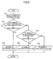
- step 41 the number of times of determination stored in the memory is read.
- step 42 whether the number of times of determination of no urea aqueous solution is equal to or larger than a predetermined value or not is determined.
- the program proceeds to step 44 and it is determined that no urea aqueous solution remains.
- the program proceeds to step 43.
- step 43 whether the number of times of determination of a different kind is equal to or larger than the predetermined value or not is determined.
- the program proceeds to step 45 and it is determined that the urea aqueous solution is a solution of a different kind.
- the program proceeds to step 46, and it is determined that the urea aqueous solution is correct one.
- the reducing agent determining process when the number of times the concentration of the urea aqueous solution is successively determined to be equal to or higher than the upper limit threshold or to be equal to or lower than the lower limit threshold becomes a predetermined value or larger, it is determined that no urea aqueous solution remains or the urea aqueous solution is a solution of a different kind. On the other hand, when the urea aqueous solution concentration lies between the lower limit threshold and the upper limit threshold, it is determined that the urea aqueous solution is correct one.
- the urea aqueous solution around the detecting unit 32B is limited, and its convection is suppressed. Consequently, even when the vehicle is running, variations in the urea aqueous solution concentration detected by the sensor 32 are reduced, and it can be discriminated with high accuracy that the urea aqueous solution does not remain, the urea aqueous solution is a solution of a different kind, or the urea aqueous solution is correct one.
- one (1) may be uniformly added to the number of times of determination of no urea aqueous solution when the urea aqueous solution concentration becomes equal to or higher than the upper limit threshold, and one may be uniformly added to the number of times of determination of a solution of different kind when the urea aqueous solution concentration becomes equal to or lower than the lower limit threshold.
- the driver of the vehicle may be notified of the fact with an alarm or the like. In this case, the driver of the vehicle can grasp that the urea aqueous solution is not correct at an early stage and take a proper action such as replacement, thereby enabling the functions of the exhaust gas purifying apparatus to be maintained.
- EEPROM Electrical Erasable Programmable Read Only Memory
- EEPROM Electrically Erasable Programmable Read Only Memory
- the liquid reducing agent discriminating apparatus can always discriminate one of such three conditions that there is no remainder of liquid reducing agent, there remains a solution of a different kind, and there remains correct liquid reducing agent even when the sensor for outputting a signal in relation to concentration of the liquid reducing agent on the basis of the characteristic of heat transmission between two points apart from each other is mounted on a mobile vehicle.
Landscapes
- Chemical & Material Sciences (AREA)
- Engineering & Computer Science (AREA)
- Chemical Kinetics & Catalysis (AREA)
- Health & Medical Sciences (AREA)
- Biochemistry (AREA)
- Combustion & Propulsion (AREA)
- General Health & Medical Sciences (AREA)
- General Physics & Mathematics (AREA)
- Immunology (AREA)
- Pathology (AREA)
- Analytical Chemistry (AREA)
- Toxicology (AREA)
- Life Sciences & Earth Sciences (AREA)
- Physics & Mathematics (AREA)
- Mechanical Engineering (AREA)
- General Engineering & Computer Science (AREA)
- Exhaust Gas After Treatment (AREA)
- Combined Controls Of Internal Combustion Engines (AREA)
- Sampling And Sample Adjustment (AREA)
- Automatic Analysis And Handling Materials Therefor (AREA)
- Investigating Or Analyzing Materials Using Thermal Means (AREA)
Applications Claiming Priority (2)
| Application Number | Priority Date | Filing Date | Title |
|---|---|---|---|
| JP2004315615A JP3686669B1 (ja) | 2004-10-29 | 2004-10-29 | 液体還元剤判別装置 |
| PCT/JP2005/017284 WO2006046367A1 (fr) | 2004-10-29 | 2005-09-20 | Appareil d’évaluation d’un agent réducteur de liquide |
Publications (3)
| Publication Number | Publication Date |
|---|---|
| EP1811146A1 true EP1811146A1 (fr) | 2007-07-25 |
| EP1811146A4 EP1811146A4 (fr) | 2010-11-17 |
| EP1811146B1 EP1811146B1 (fr) | 2011-10-12 |
Family
ID=35004097
Family Applications (1)
| Application Number | Title | Priority Date | Filing Date |
|---|---|---|---|
| EP05785706A Expired - Lifetime EP1811146B1 (fr) | 2004-10-29 | 2005-09-20 | Appareil d'évaluation d'un agent réducteur liquide |
Country Status (7)
| Country | Link |
|---|---|
| US (1) | US7587288B2 (fr) |
| EP (1) | EP1811146B1 (fr) |
| JP (1) | JP3686669B1 (fr) |
| CN (1) | CN100504046C (fr) |
| AT (1) | ATE528490T1 (fr) |
| ES (1) | ES2370920T3 (fr) |
| WO (1) | WO2006046367A1 (fr) |
Cited By (2)
| Publication number | Priority date | Publication date | Assignee | Title |
|---|---|---|---|---|
| EP2067517A3 (fr) * | 2007-12-04 | 2011-11-30 | Caterpillar Inc. | Systèmes et procédés pour surveiller la qualité d'un agent de réduction |
| EP2072772A4 (fr) * | 2006-10-12 | 2013-05-29 | Nissan Diesel Motor Co | Épurateur de gaz d'échappement de moteur |
Families Citing this family (19)
| Publication number | Priority date | Publication date | Assignee | Title |
|---|---|---|---|---|
| JP3687917B2 (ja) * | 2003-10-31 | 2005-08-24 | 日産ディーゼル工業株式会社 | 液体還元剤の濃度及び残量検出装置 |
| JP4799289B2 (ja) * | 2006-06-26 | 2011-10-26 | Udトラックス株式会社 | エンジンの排気浄化装置 |
| US7946109B2 (en) * | 2006-12-14 | 2011-05-24 | GM Global Technology Operations LLC | Emissions conformance for an exhaust after-treatment system having a dosing agent supply |
| JP4832326B2 (ja) * | 2007-02-06 | 2011-12-07 | Udトラックス株式会社 | エンジンの排気浄化装置 |
| JP4895888B2 (ja) * | 2007-03-29 | 2012-03-14 | Udトラックス株式会社 | 還元剤添加システムの解凍判定装置及びエンジンの排気浄化装置 |
| JP4895887B2 (ja) * | 2007-03-29 | 2012-03-14 | Udトラックス株式会社 | エンジンの排気浄化装置 |
| JP4895889B2 (ja) * | 2007-03-29 | 2012-03-14 | Udトラックス株式会社 | 凍結判定装置 |
| JP4710868B2 (ja) * | 2007-04-25 | 2011-06-29 | トヨタ自動車株式会社 | 内燃機関の排気浄化装置 |
| DE102007024782B4 (de) * | 2007-05-26 | 2011-08-25 | Eichenauer Heizelemente GmbH & Co. KG, 76870 | Heizeinsatz und dessen Verwendung in einem Harnstoffversorgungssystem |
| US8978450B2 (en) | 2010-07-22 | 2015-03-17 | Watlow Electric Manufacturing Company | Combination fluid sensor system |
| KR101416408B1 (ko) * | 2012-12-31 | 2014-07-09 | 기아자동차 주식회사 | 요소 품질 센서의 고장 진단 방법 및 장치 |
| JP6167781B2 (ja) * | 2013-09-12 | 2017-07-26 | いすゞ自動車株式会社 | 尿素水濃度誤診断防止システム |
| US9845717B2 (en) * | 2014-10-28 | 2017-12-19 | Ford Global Technologies, Llc | Systems and methods for managing diesel exhaust fluid stratification |
| KR101673336B1 (ko) * | 2015-04-02 | 2016-11-07 | 현대자동차 주식회사 | 차량의 운전자 강제 유도 방법 및 장치 |
| CN112327705B (zh) * | 2020-11-12 | 2021-12-31 | 浙江工业大学 | 一种基于铜丝溶断的智能小车停车控制系统、方法 |
| CN113758534B (zh) * | 2021-07-29 | 2024-04-19 | 江铃汽车股份有限公司 | 一种燃料存量显示方法、系统、可读存储介质及车辆 |
| IT202100032027A1 (it) * | 2021-12-21 | 2023-06-21 | Errecinque S R L | Metodo ed apparato per monitorare un degrado termico di una soluzione riducente |
| CN114495447B (zh) * | 2022-01-17 | 2024-03-19 | 潍柴动力股份有限公司 | 一种发动机尿素溶液浓度异常的报警方法及装置 |
| CN114382573A (zh) * | 2022-03-24 | 2022-04-22 | 潍柴动力股份有限公司 | 一种尿素喷射量确定方法及装置 |
Family Cites Families (27)
| Publication number | Priority date | Publication date | Assignee | Title |
|---|---|---|---|---|
| JPH04282433A (ja) * | 1991-03-11 | 1992-10-07 | Snow Brand Milk Prod Co Ltd | 液体の濃度測定方法及び装置 |
| US6063350A (en) * | 1997-04-02 | 2000-05-16 | Clean Diesel Technologies, Inc. | Reducing nox emissions from an engine by temperature-controlled urea injection for selective catalytic reduction |
| JP3264221B2 (ja) * | 1997-07-28 | 2002-03-11 | 株式会社デンソー | 内燃機関の空燃比制御装置 |
| DE19736384A1 (de) * | 1997-08-21 | 1999-02-25 | Man Nutzfahrzeuge Ag | Verfahren zur Dosierung eines Reduktionsmittels in stickoxidhaltiges Abgas einer Brennkraftmaschine |
| DE19756251C1 (de) | 1997-12-17 | 1999-07-22 | Siemens Ag | Verfahren und Vorrichtung zur Reduzierung der Stickoxide im Abgas einer Verbrennungsanlage |
| DE19818448A1 (de) | 1998-04-24 | 1999-10-28 | Siemens Ag | Verfahren und Vorrichtung zur katalytischen Reduzierung von Stickoxiden im Abgas einer Verbrennungsanlage |
| JP2000027627A (ja) | 1998-07-13 | 2000-01-25 | Hino Motors Ltd | 排気ガス浄化触媒用還元剤保温装置及びそれを組込んだ排気ガス浄化装置 |
| DE19841770A1 (de) | 1998-09-11 | 2000-04-06 | Siemens Ag | Vorrichtung und Verfahren zur Füllstandsmessung |
| JP2001020724A (ja) * | 1999-07-07 | 2001-01-23 | Isuzu Motors Ltd | ディーゼルエンジンのNOx浄化装置 |
| DE19933798C2 (de) * | 1999-07-19 | 2001-06-21 | Siemens Ag | Vorrichtung und Verfahren zur Abgasnachbehandlung bei einer Brennkraftmaschine |
| DE10047519A1 (de) * | 2000-09-22 | 2002-04-18 | Bosch Gmbh Robert | Verfahren und Vorrichtung zur Dosierung eines Reduktionsmittels zur Entfernung von Stickoxiden aus Abgasen |
| DE10047594A1 (de) | 2000-09-26 | 2002-04-18 | Siemens Ag | Verfahren und Vorrichtung zum Bestimmen des Füllstandes einer Flüssigkeit in einem Behälter |
| DE10102237A1 (de) | 2001-01-19 | 2002-08-08 | Bosch Gmbh Robert | Vorrichtung zur Dosierung einer Harnstofflösung |
| JP2002371831A (ja) * | 2001-06-13 | 2002-12-26 | Nissan Diesel Motor Co Ltd | 自動車の排ガス浄化装置 |
| JP4270428B2 (ja) | 2001-06-13 | 2009-06-03 | 日産ディーゼル工業株式会社 | 還元剤溶液の自動調合装置 |
| DE10155675A1 (de) * | 2001-08-18 | 2003-05-28 | Bosch Gmbh Robert | Verfahren und Vorrichtung zur Speicherung und Dosierung eines Reduktionsmittels |
| WO2003100225A1 (fr) * | 2002-05-07 | 2003-12-04 | Extengine Transport Systems | Systeme de reglage d'emissions |
| WO2004025286A1 (fr) * | 2002-09-10 | 2004-03-25 | Mitsui Mining & Smelting Co., Ltd. | Systeme d'identification de concentration d'uree, procede d'identification de concentration d'uree, systeme de reduction de gaz d'echappement d'automobile mettant en oeuvre ledit systeme et procede de reduction de gaz d'echappement d'automobile |
| JP4238598B2 (ja) * | 2003-02-26 | 2009-03-18 | 三菱ふそうトラック・バス株式会社 | 内燃機関のNOx浄化装置 |
| EP1653227B1 (fr) | 2003-07-11 | 2017-10-25 | SUN-A Corporation | Dispositif et procede de detection de type de liquide |
| JP2005030888A (ja) * | 2003-07-11 | 2005-02-03 | Mitsui Mining & Smelting Co Ltd | 流量・液種検知装置および流量・液種検知方法 |
| JP3751962B2 (ja) * | 2003-09-05 | 2006-03-08 | 日産ディーゼル工業株式会社 | エンジンの排気浄化装置 |
| JP3687915B2 (ja) * | 2003-10-27 | 2005-08-24 | 日産ディーゼル工業株式会社 | 液体判別装置 |
| JP3687916B2 (ja) * | 2003-10-28 | 2005-08-24 | 日産ディーゼル工業株式会社 | エンジンの排気浄化装置 |
| JP3687917B2 (ja) * | 2003-10-31 | 2005-08-24 | 日産ディーゼル工業株式会社 | 液体還元剤の濃度及び残量検出装置 |
| WO2005093382A1 (fr) | 2004-03-29 | 2005-10-06 | Nissan Diesel Motor Co., Ltd. | Structure pour conteneur d’agent réducteur |
| JP4193748B2 (ja) | 2004-04-19 | 2008-12-10 | ソニー株式会社 | 沈胴式レンズ鏡筒および撮像装置 |
-
2004
- 2004-10-29 JP JP2004315615A patent/JP3686669B1/ja not_active Expired - Fee Related
-
2005
- 2005-09-20 CN CNB2005800375336A patent/CN100504046C/zh not_active Expired - Fee Related
- 2005-09-20 ES ES05785706T patent/ES2370920T3/es not_active Expired - Lifetime
- 2005-09-20 WO PCT/JP2005/017284 patent/WO2006046367A1/fr not_active Ceased
- 2005-09-20 AT AT05785706T patent/ATE528490T1/de not_active IP Right Cessation
- 2005-09-20 EP EP05785706A patent/EP1811146B1/fr not_active Expired - Lifetime
-
2007
- 2007-04-27 US US11/790,759 patent/US7587288B2/en active Active
Cited By (2)
| Publication number | Priority date | Publication date | Assignee | Title |
|---|---|---|---|---|
| EP2072772A4 (fr) * | 2006-10-12 | 2013-05-29 | Nissan Diesel Motor Co | Épurateur de gaz d'échappement de moteur |
| EP2067517A3 (fr) * | 2007-12-04 | 2011-11-30 | Caterpillar Inc. | Systèmes et procédés pour surveiller la qualité d'un agent de réduction |
Also Published As
| Publication number | Publication date |
|---|---|
| CN100504046C (zh) | 2009-06-24 |
| US7587288B2 (en) | 2009-09-08 |
| WO2006046367A1 (fr) | 2006-05-04 |
| ATE528490T1 (de) | 2011-10-15 |
| CN101052789A (zh) | 2007-10-10 |
| US20070204678A1 (en) | 2007-09-06 |
| JP3686669B1 (ja) | 2005-08-24 |
| EP1811146B1 (fr) | 2011-10-12 |
| JP2006125322A (ja) | 2006-05-18 |
| EP1811146A4 (fr) | 2010-11-17 |
| ES2370920T3 (es) | 2011-12-23 |
Similar Documents
| Publication | Publication Date | Title |
|---|---|---|
| US7587288B2 (en) | Condition discriminating apparatus for liquid reducing agent | |
| US7651262B2 (en) | Apparatus for discriminating liquid reducing agent | |
| EP1811144B1 (fr) | Appareil de purification de gaz d'echappement | |
| EP2072772B1 (fr) | Épurateur de gaz d'échappement de moteur | |
| JP3687917B2 (ja) | 液体還元剤の濃度及び残量検出装置 | |
| EP2551480B1 (fr) | Dispositif d'épuration des gaz d'échappement de moteur | |
| US7658093B2 (en) | Liquid discriminating apparatus and liquid discriminating method | |
| JP6390952B2 (ja) | 車両の制御装置 | |
| JP4327072B2 (ja) | 排気浄化装置の液体還元剤判別システム | |
| JP4832326B2 (ja) | エンジンの排気浄化装置 |
Legal Events
| Date | Code | Title | Description |
|---|---|---|---|
| PUAI | Public reference made under article 153(3) epc to a published international application that has entered the european phase |
Free format text: ORIGINAL CODE: 0009012 |
|
| 17P | Request for examination filed |
Effective date: 20070502 |
|
| AK | Designated contracting states |
Kind code of ref document: A1 Designated state(s): AT BE BG CH CY CZ DE DK EE ES FI FR GB GR HU IE IS IT LI LT LU LV MC NL PL PT RO SE SI SK TR |
|
| DAX | Request for extension of the european patent (deleted) | ||
| A4 | Supplementary search report drawn up and despatched |
Effective date: 20101020 |
|
| RIC1 | Information provided on ipc code assigned before grant |
Ipc: G01N 27/00 20060101ALI20101014BHEP Ipc: F02D 45/00 20060101ALI20101014BHEP Ipc: F01N 3/08 20060101AFI20060914BHEP Ipc: G01F 23/26 20060101ALI20101014BHEP |
|
| GRAP | Despatch of communication of intention to grant a patent |
Free format text: ORIGINAL CODE: EPIDOSNIGR1 |
|
| RIC1 | Information provided on ipc code assigned before grant |
Ipc: G01F 23/26 20060101ALI20110509BHEP Ipc: G01N 27/00 20060101ALI20110509BHEP Ipc: F02D 45/00 20060101ALI20110509BHEP Ipc: F01N 3/08 20060101AFI20110509BHEP |
|
| GRAS | Grant fee paid |
Free format text: ORIGINAL CODE: EPIDOSNIGR3 |
|
| GRAA | (expected) grant |
Free format text: ORIGINAL CODE: 0009210 |
|
| AK | Designated contracting states |
Kind code of ref document: B1 Designated state(s): AT BE BG CH CY CZ DE DK EE ES FI FR GB GR HU IE IS IT LI LT LU LV MC NL PL PT RO SE SI SK TR |
|
| REG | Reference to a national code |
Ref country code: GB Ref legal event code: FG4D |
|
| REG | Reference to a national code |
Ref country code: CH Ref legal event code: EP |
|
| REG | Reference to a national code |
Ref country code: IE Ref legal event code: FG4D |
|
| REG | Reference to a national code |
Ref country code: DE Ref legal event code: R096 Ref document number: 602005030608 Country of ref document: DE Effective date: 20111208 |
|
| REG | Reference to a national code |
Ref country code: ES Ref legal event code: FG2A Ref document number: 2370920 Country of ref document: ES Kind code of ref document: T3 Effective date: 20111223 |
|
| REG | Reference to a national code |
Ref country code: SE Ref legal event code: TRGR |
|
| REG | Reference to a national code |
Ref country code: NL Ref legal event code: T3 |
|
| LTIE | Lt: invalidation of european patent or patent extension |
Effective date: 20111012 |
|
| REG | Reference to a national code |
Ref country code: AT Ref legal event code: MK05 Ref document number: 528490 Country of ref document: AT Kind code of ref document: T Effective date: 20111012 |
|
| PG25 | Lapsed in a contracting state [announced via postgrant information from national office to epo] |
Ref country code: IS Free format text: LAPSE BECAUSE OF FAILURE TO SUBMIT A TRANSLATION OF THE DESCRIPTION OR TO PAY THE FEE WITHIN THE PRESCRIBED TIME-LIMIT Effective date: 20120212 Ref country code: LT Free format text: LAPSE BECAUSE OF FAILURE TO SUBMIT A TRANSLATION OF THE DESCRIPTION OR TO PAY THE FEE WITHIN THE PRESCRIBED TIME-LIMIT Effective date: 20111012 |
|
| PG25 | Lapsed in a contracting state [announced via postgrant information from national office to epo] |
Ref country code: LV Free format text: LAPSE BECAUSE OF FAILURE TO SUBMIT A TRANSLATION OF THE DESCRIPTION OR TO PAY THE FEE WITHIN THE PRESCRIBED TIME-LIMIT Effective date: 20111012 Ref country code: GR Free format text: LAPSE BECAUSE OF FAILURE TO SUBMIT A TRANSLATION OF THE DESCRIPTION OR TO PAY THE FEE WITHIN THE PRESCRIBED TIME-LIMIT Effective date: 20120113 Ref country code: SI Free format text: LAPSE BECAUSE OF FAILURE TO SUBMIT A TRANSLATION OF THE DESCRIPTION OR TO PAY THE FEE WITHIN THE PRESCRIBED TIME-LIMIT Effective date: 20111012 |
|
| PG25 | Lapsed in a contracting state [announced via postgrant information from national office to epo] |
Ref country code: CY Free format text: LAPSE BECAUSE OF FAILURE TO SUBMIT A TRANSLATION OF THE DESCRIPTION OR TO PAY THE FEE WITHIN THE PRESCRIBED TIME-LIMIT Effective date: 20111012 |
|
| PG25 | Lapsed in a contracting state [announced via postgrant information from national office to epo] |
Ref country code: EE Free format text: LAPSE BECAUSE OF FAILURE TO SUBMIT A TRANSLATION OF THE DESCRIPTION OR TO PAY THE FEE WITHIN THE PRESCRIBED TIME-LIMIT Effective date: 20111012 Ref country code: DK Free format text: LAPSE BECAUSE OF FAILURE TO SUBMIT A TRANSLATION OF THE DESCRIPTION OR TO PAY THE FEE WITHIN THE PRESCRIBED TIME-LIMIT Effective date: 20111012 Ref country code: SK Free format text: LAPSE BECAUSE OF FAILURE TO SUBMIT A TRANSLATION OF THE DESCRIPTION OR TO PAY THE FEE WITHIN THE PRESCRIBED TIME-LIMIT Effective date: 20111012 Ref country code: BG Free format text: LAPSE BECAUSE OF FAILURE TO SUBMIT A TRANSLATION OF THE DESCRIPTION OR TO PAY THE FEE WITHIN THE PRESCRIBED TIME-LIMIT Effective date: 20120112 Ref country code: CZ Free format text: LAPSE BECAUSE OF FAILURE TO SUBMIT A TRANSLATION OF THE DESCRIPTION OR TO PAY THE FEE WITHIN THE PRESCRIBED TIME-LIMIT Effective date: 20111012 |
|
| PLBE | No opposition filed within time limit |
Free format text: ORIGINAL CODE: 0009261 |
|
| STAA | Information on the status of an ep patent application or granted ep patent |
Free format text: STATUS: NO OPPOSITION FILED WITHIN TIME LIMIT |
|
| PG25 | Lapsed in a contracting state [announced via postgrant information from national office to epo] |
Ref country code: PL Free format text: LAPSE BECAUSE OF FAILURE TO SUBMIT A TRANSLATION OF THE DESCRIPTION OR TO PAY THE FEE WITHIN THE PRESCRIBED TIME-LIMIT Effective date: 20111012 Ref country code: RO Free format text: LAPSE BECAUSE OF FAILURE TO SUBMIT A TRANSLATION OF THE DESCRIPTION OR TO PAY THE FEE WITHIN THE PRESCRIBED TIME-LIMIT Effective date: 20111012 |
|
| 26N | No opposition filed |
Effective date: 20120713 |
|
| REG | Reference to a national code |
Ref country code: DE Ref legal event code: R097 Ref document number: 602005030608 Country of ref document: DE Effective date: 20120713 |
|
| PG25 | Lapsed in a contracting state [announced via postgrant information from national office to epo] |
Ref country code: AT Free format text: LAPSE BECAUSE OF FAILURE TO SUBMIT A TRANSLATION OF THE DESCRIPTION OR TO PAY THE FEE WITHIN THE PRESCRIBED TIME-LIMIT Effective date: 20111012 |
|
| PG25 | Lapsed in a contracting state [announced via postgrant information from national office to epo] |
Ref country code: MC Free format text: LAPSE BECAUSE OF NON-PAYMENT OF DUE FEES Effective date: 20120930 |
|
| REG | Reference to a national code |
Ref country code: CH Ref legal event code: PL |
|
| GBPC | Gb: european patent ceased through non-payment of renewal fee |
Effective date: 20120920 |
|
| REG | Reference to a national code |
Ref country code: IE Ref legal event code: MM4A |
|
| PG25 | Lapsed in a contracting state [announced via postgrant information from national office to epo] |
Ref country code: FI Free format text: LAPSE BECAUSE OF FAILURE TO SUBMIT A TRANSLATION OF THE DESCRIPTION OR TO PAY THE FEE WITHIN THE PRESCRIBED TIME-LIMIT Effective date: 20111012 |
|
| PG25 | Lapsed in a contracting state [announced via postgrant information from national office to epo] |
Ref country code: GB Free format text: LAPSE BECAUSE OF NON-PAYMENT OF DUE FEES Effective date: 20120920 Ref country code: LI Free format text: LAPSE BECAUSE OF NON-PAYMENT OF DUE FEES Effective date: 20120930 Ref country code: IE Free format text: LAPSE BECAUSE OF NON-PAYMENT OF DUE FEES Effective date: 20120920 Ref country code: CH Free format text: LAPSE BECAUSE OF NON-PAYMENT OF DUE FEES Effective date: 20120930 |
|
| PG25 | Lapsed in a contracting state [announced via postgrant information from national office to epo] |
Ref country code: TR Free format text: LAPSE BECAUSE OF FAILURE TO SUBMIT A TRANSLATION OF THE DESCRIPTION OR TO PAY THE FEE WITHIN THE PRESCRIBED TIME-LIMIT Effective date: 20111012 |
|
| PG25 | Lapsed in a contracting state [announced via postgrant information from national office to epo] |
Ref country code: LU Free format text: LAPSE BECAUSE OF NON-PAYMENT OF DUE FEES Effective date: 20120920 |
|
| PG25 | Lapsed in a contracting state [announced via postgrant information from national office to epo] |
Ref country code: HU Free format text: LAPSE BECAUSE OF FAILURE TO SUBMIT A TRANSLATION OF THE DESCRIPTION OR TO PAY THE FEE WITHIN THE PRESCRIBED TIME-LIMIT Effective date: 20050920 Ref country code: PT Free format text: LAPSE BECAUSE OF FAILURE TO SUBMIT A TRANSLATION OF THE DESCRIPTION OR TO PAY THE FEE WITHIN THE PRESCRIBED TIME-LIMIT Effective date: 20111012 |
|
| REG | Reference to a national code |
Ref country code: FR Ref legal event code: PLFP Year of fee payment: 11 |
|
| REG | Reference to a national code |
Ref country code: FR Ref legal event code: PLFP Year of fee payment: 12 |
|
| REG | Reference to a national code |
Ref country code: FR Ref legal event code: PLFP Year of fee payment: 13 |
|
| REG | Reference to a national code |
Ref country code: FR Ref legal event code: PLFP Year of fee payment: 14 |
|
| REG | Reference to a national code |
Ref country code: DE Ref legal event code: R081 Ref document number: 602005030608 Country of ref document: DE Owner name: VOLVO TRUCK CORPORATION, SE Free format text: FORMER OWNER: NISSAN DIESEL MOTOR CO., LTD., AGEO, SAITAMA, JP |
|
| REG | Reference to a national code |
Ref country code: BE Ref legal event code: PD Owner name: UD TRUCKS CORPORATION; JP Free format text: DETAILS ASSIGNMENT: CHANGE OF OWNER(S), ASSIGNMENT; FORMER OWNER NAME: UD TRUCKS CORPORATION Effective date: 20211018 Ref country code: BE Ref legal event code: HC Owner name: VOLVO TRUCK CORPORATION; SE Free format text: DETAILS ASSIGNMENT: CHANGE OF OWNER(S), CHANGE OF OWNER(S) NAME; FORMER OWNER NAME: VOLVO GROUP SWEDEN AB Effective date: 20211018 |
|
| REG | Reference to a national code |
Ref country code: NL Ref legal event code: PD Owner name: VOLVO TRUCK CORPORATION; SE Free format text: DETAILS ASSIGNMENT: CHANGE OF OWNER(S), ASSIGNMENT; FORMER OWNER NAME: VOLVO GROUP SWEDEN AB Effective date: 20211125 |
|
| REG | Reference to a national code |
Ref country code: ES Ref legal event code: PC2A Owner name: VOLVO TRUCK CORPORATION Effective date: 20220310 |
|
| PGFP | Annual fee paid to national office [announced via postgrant information from national office to epo] |
Ref country code: SE Payment date: 20220923 Year of fee payment: 18 Ref country code: NL Payment date: 20220926 Year of fee payment: 18 Ref country code: DE Payment date: 20220527 Year of fee payment: 18 |
|
| PGFP | Annual fee paid to national office [announced via postgrant information from national office to epo] |
Ref country code: FR Payment date: 20220927 Year of fee payment: 18 Ref country code: BE Payment date: 20220926 Year of fee payment: 18 |
|
| PGFP | Annual fee paid to national office [announced via postgrant information from national office to epo] |
Ref country code: IT Payment date: 20220926 Year of fee payment: 18 Ref country code: ES Payment date: 20221013 Year of fee payment: 18 |
|
| REG | Reference to a national code |
Ref country code: DE Ref legal event code: R119 Ref document number: 602005030608 Country of ref document: DE |
|
| REG | Reference to a national code |
Ref country code: SE Ref legal event code: EUG |
|
| REG | Reference to a national code |
Ref country code: NL Ref legal event code: MM Effective date: 20231001 |
|
| REG | Reference to a national code |
Ref country code: BE Ref legal event code: MM Effective date: 20230930 |
|
| PG25 | Lapsed in a contracting state [announced via postgrant information from national office to epo] |
Ref country code: NL Free format text: LAPSE BECAUSE OF NON-PAYMENT OF DUE FEES Effective date: 20231001 |
|
| PG25 | Lapsed in a contracting state [announced via postgrant information from national office to epo] |
Ref country code: NL Free format text: LAPSE BECAUSE OF NON-PAYMENT OF DUE FEES Effective date: 20231001 |
|
| PG25 | Lapsed in a contracting state [announced via postgrant information from national office to epo] |
Ref country code: FR Free format text: LAPSE BECAUSE OF NON-PAYMENT OF DUE FEES Effective date: 20230930 Ref country code: DE Free format text: LAPSE BECAUSE OF NON-PAYMENT OF DUE FEES Effective date: 20240403 |
|
| PG25 | Lapsed in a contracting state [announced via postgrant information from national office to epo] |
Ref country code: SE Free format text: LAPSE BECAUSE OF NON-PAYMENT OF DUE FEES Effective date: 20230921 Ref country code: BE Free format text: LAPSE BECAUSE OF NON-PAYMENT OF DUE FEES Effective date: 20230930 |
|
| REG | Reference to a national code |
Ref country code: ES Ref legal event code: FD2A Effective date: 20241029 |
|
| PG25 | Lapsed in a contracting state [announced via postgrant information from national office to epo] |
Ref country code: IT Free format text: LAPSE BECAUSE OF NON-PAYMENT OF DUE FEES Effective date: 20230920 |
|
| PG25 | Lapsed in a contracting state [announced via postgrant information from national office to epo] |
Ref country code: IT Free format text: LAPSE BECAUSE OF NON-PAYMENT OF DUE FEES Effective date: 20230920 |
|
| PG25 | Lapsed in a contracting state [announced via postgrant information from national office to epo] |
Ref country code: ES Free format text: LAPSE BECAUSE OF NON-PAYMENT OF DUE FEES Effective date: 20230921 |
|
| PG25 | Lapsed in a contracting state [announced via postgrant information from national office to epo] |
Ref country code: ES Free format text: LAPSE BECAUSE OF NON-PAYMENT OF DUE FEES Effective date: 20230921 |