EP1811151A2 - Moteur à combustion à piston élévateur - Google Patents
Moteur à combustion à piston élévateur Download PDFInfo
- Publication number
- EP1811151A2 EP1811151A2 EP06025534A EP06025534A EP1811151A2 EP 1811151 A2 EP1811151 A2 EP 1811151A2 EP 06025534 A EP06025534 A EP 06025534A EP 06025534 A EP06025534 A EP 06025534A EP 1811151 A2 EP1811151 A2 EP 1811151A2
- Authority
- EP
- European Patent Office
- Prior art keywords
- lever
- pull
- transmission lever
- push rod
- internal combustion
- Prior art date
- Legal status (The legal status is an assumption and is not a legal conclusion. Google has not performed a legal analysis and makes no representation as to the accuracy of the status listed.)
- Granted
Links
- 238000002485 combustion reaction Methods 0.000 title claims abstract description 24
- 230000005540 biological transmission Effects 0.000 claims abstract description 61
- 230000006835 compression Effects 0.000 description 4
- 238000007906 compression Methods 0.000 description 4
- 238000006073 displacement reaction Methods 0.000 description 2
- 230000008878 coupling Effects 0.000 description 1
- 238000010168 coupling process Methods 0.000 description 1
- 238000005859 coupling reaction Methods 0.000 description 1
- 230000000694 effects Effects 0.000 description 1
Images


Classifications
-
- F—MECHANICAL ENGINEERING; LIGHTING; HEATING; WEAPONS; BLASTING
- F02—COMBUSTION ENGINES; HOT-GAS OR COMBUSTION-PRODUCT ENGINE PLANTS
- F02B—INTERNAL-COMBUSTION PISTON ENGINES; COMBUSTION ENGINES IN GENERAL
- F02B75/00—Other engines
- F02B75/04—Engines with variable distances between pistons at top dead-centre positions and cylinder heads
- F02B75/048—Engines with variable distances between pistons at top dead-centre positions and cylinder heads by means of a variable crank stroke length
-
- F—MECHANICAL ENGINEERING; LIGHTING; HEATING; WEAPONS; BLASTING
- F02—COMBUSTION ENGINES; HOT-GAS OR COMBUSTION-PRODUCT ENGINE PLANTS
- F02B—INTERNAL-COMBUSTION PISTON ENGINES; COMBUSTION ENGINES IN GENERAL
- F02B75/00—Other engines
- F02B75/04—Engines with variable distances between pistons at top dead-centre positions and cylinder heads
-
- F—MECHANICAL ENGINEERING; LIGHTING; HEATING; WEAPONS; BLASTING
- F01—MACHINES OR ENGINES IN GENERAL; ENGINE PLANTS IN GENERAL; STEAM ENGINES
- F01B—MACHINES OR ENGINES, IN GENERAL OR OF POSITIVE-DISPLACEMENT TYPE, e.g. STEAM ENGINES
- F01B9/00—Reciprocating-piston machines or engines characterised by connections between pistons and main shafts, not specific to groups F01B1/00 - F01B7/00
- F01B9/02—Reciprocating-piston machines or engines characterised by connections between pistons and main shafts, not specific to groups F01B1/00 - F01B7/00 with crankshaft
-
- F—MECHANICAL ENGINEERING; LIGHTING; HEATING; WEAPONS; BLASTING
- F02—COMBUSTION ENGINES; HOT-GAS OR COMBUSTION-PRODUCT ENGINE PLANTS
- F02B—INTERNAL-COMBUSTION PISTON ENGINES; COMBUSTION ENGINES IN GENERAL
- F02B75/00—Other engines
Definitions
- the invention relates to reciprocating internal combustion engines with a crank mechanism and an indirectly coupled to the piston, the cylinder axis intersecting transmission lever, which is hinged on the one hand to a connecting rod of a crank mechanism and on the other hand guided in a cylinder block, but adjustable storage.
- the invention has for its object to achieve a greater variation in the translation of movements between the crank mechanism and piston in a generic internal combustion engine.
- the pull and push rod connected to a piston of the internal combustion engine at its end facing the transmission lever on a guide, which is preferably designed as a pivotally mounted shoe, which engages in a longitudinally extending on the transmission lever guide.
- the transmission lever is pivotally connected on the one hand with a connecting rod of the crankshaft and on the other hand, the transmission lever with an actuator, for variably setting the articulation of the pull and push rod to the transmission lever connected.
- the guide of the pull and push rod is effected by a guide lever which is pivotally connected on the one hand with the pull and push rod and on the other hand is pivotally articulated on the cylinder block.
- the shoe can alternatively as any guide which displaceably guides the connecting rod on the transmission lever, z. B. as a slot in the transmission lever, in which engages a pin formed on the connecting rod, be formed.
- crank mechanism and piston With the embodiment according to the invention, a greater variation of the translation of movements between crank mechanism and piston can be realized than in the previously known generic solution. It move in addition to the piston in the first embodiment, only three transmission elements oscillating and that is the transmission lever, a connecting rod and the piston connected to the shoe and provided with pull and push rod.
- the necessary guidance of the pull and push rod of the piston also takes place by a guide lever, which is mounted to reduce the forces occurring vertically displaceable on the cylinder block.
- Another variant provides to guide the pull and push rod of the piston in place of the guide lever by a parallel to the cylinder axis arranged slide.
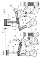
- FIG. 1 shows the engine of a reciprocating internal combustion engine according to the invention in a schematic representation.
- a cylinder 1 is arranged, in which a piston 2 moves and forms a volume-variable working space in a known manner depending on the size of the stroke.
- the crankshaft 3 runs in a bearing 30ZB in the cylinder block, which is arranged offset to the cylinder axis ZA, in the direction of rotation DR.
- a connecting rod 4 is mounted, whose outer bearing eye is hinged at the end of a transmission lever 5.
- the piston 2 is positively connected to a pull and push rod 6, at the other end a pin 61 is arranged, which engages in a slot 51 of the transmission lever 5.
- the transmission lever 5 is pivotally mounted in a cylinder block in adjustable guided storage 8.
- a form-fitting bearing guide 8ZB is arranged, in which the bearing 8 can be set determined by an actuator, not shown in position.
- the controllable by the actuator not shown changes in the position of the bearing 8 are shown symbolically in Figure 1 by the designated arrow S8.
- the bearing guide 8ZB is always directed transversely to the cylinder axis ZA, but it can be arranged at right angles or in an expedient manner extending inclined. Inclined to the cylinder axis ZA extending bearing guides 8ZB are not shown in the figures.
- a guide lever 9 is pivotally articulated, which is hinged on its side remote from the pull and push rod 6 side pivotally mounted on the cylinder block ZB. With an adjustment of the bearing 8 of the transmission lever 5, the transmission lever 5 facing side of the connecting rod 4 due to the stationary, but pivotally mounted on the cylinder block ZB guide lever 9 relative to the transmission lever. 5 moved in the slot 51.
- FIG. 3 shows the engine in a setting according to FIG. 2 for a large stroke, but with a position of the crankshaft 3 in which the piston 2 has reached the bottom dead center UT.
- the pull and push rod 6 pivots from its vertical and is forcibly guided by the guide lever 9 in the slot 51 of the transmission lever 5.
- Figures 4 to 7 show a variant of the solution according to the invention, in which the friction between the shoe 7 and the pin 61 of the pull and push rod 6 and the transmission lever 5 is further reduced.
- the adjustment of the stroke of the piston 2 is also carried out by moving the transmission lever 5 by an adjusting drive, so that the articulation point of the pull and push rod 6 is moved to the transmission lever 5 according to the stroke to be set.
- the leadership of the pull and push rod 6 is also carried out by the guide lever 9, but pivotally mounted on a cylinder block ZB, vertically displaceable sliding guide 10 is articulated.
- the actuator for setting and changing the stroke consists essentially of a controllably driven worm shaft 12, which is in operative connection with a worm wheel 11.
- a controllably driven worm shaft 12 which is in operative connection with a worm wheel 11.
- the worm wheel 11 is pivoted about its pivot point 16.
- the worm wheel 11 is pivoted either up or down.
- the worm wheel 11 is spaced from the pivot point 16 on the one hand via a pivotally hinged feed lever 14 with the guide lever 9 and a sliding guide 10 hingedly connected.
- the worm wheel 11 is pivotally connected via a pivotally hinged rocker arm 15 with the transmission lever 5.
- the pivotable articulation of the feed lever 14 and the rocker 15 on the worm wheel 11 takes place via a common pivot pin. Also via a common pivot pin, the articulation of the feed lever 14 and the guide lever 9 to the arranged on the cylinder block ZB, vertically displaceable sliding guide 10.
- a two-lever 13 is pivotally hinged, the other end is stationary, but pivotally mounted on the cylinder block ZB.
- the pivotal movement of the rocker arm 15 about the pivot point 17 of the transmission lever 5 is moved, wherein the articulation point of the pull and push rod 6 on the transmission lever 5 according to the is shifted to be set stroke.
- the pivoting of the worm wheel 11 displaces the guide lever 9 articulated on the sliding guide 10, which also influences the adjustment of the articulation of the pull and push rod 6 on the transmission lever 5.
- FIGS. 4 and 6 each show a large stroke adjustment, with FIG. 4 showing the position of the piston 2 at bottom dead center UT and FIG. 6 the position of the piston 2 at top dead center TDC. From the illustrations it can be seen that the sliding guide 10 is in its lower position and the articulation point of the rocker 15 and the feed lever 14 is located on the worm wheel 11 close to the worm shaft 12.
- FIG. 5 shows the piston 2 at bottom dead center UT
- FIG. 7 shows the position of the piston 2 at top dead center OT.
- FIGS. 8 to 10 Another variant of the solution according to the invention is shown in FIGS. 8 to 10.
- the leadership of the pull and push rod 6 does not take place by means of the guide lever 9, but by a cylinder block ZB arranged slide 60ZB.
- the transmission lever 5 is also slidably and pivotally mounted to adjust the stroke in a displaceable by an actuator not shown bearing 8.
- Figure 8 shows a position of the engine after passing through top dead center OT at a high lift setting.
- the aspect ratio between the effective lever arm H4 of the connecting rod 4 on the transmission lever 5 and the effective lever arm H6 connected to the piston 2 pull and push rod 6 is about 7 to 10.
- FIG. 9 shows the engine elements at a piston position at top dead center OT and FIG. 10 at a piston position at bottom dead center UT.
- the transmission lever 5 moved by the connecting rod 4 pivots about the angle ⁇ 5, whereby the piston 2 travels the path S.
- the solution according to the invention is in addition to the reciprocating internal combustion engines for other reciprocating engines, such. B. for axial compressor or expander, can be used.
Landscapes
- Engineering & Computer Science (AREA)
- Mechanical Engineering (AREA)
- General Engineering & Computer Science (AREA)
- Chemical & Material Sciences (AREA)
- Combustion & Propulsion (AREA)
- Transmission Devices (AREA)
- Valve Device For Special Equipments (AREA)
Applications Claiming Priority (1)
| Application Number | Priority Date | Filing Date | Title |
|---|---|---|---|
| DE102006003737A DE102006003737B3 (de) | 2006-01-24 | 2006-01-24 | Hubkolben-Verbrennungsmotor |
Publications (3)
| Publication Number | Publication Date |
|---|---|
| EP1811151A2 true EP1811151A2 (fr) | 2007-07-25 |
| EP1811151A3 EP1811151A3 (fr) | 2008-07-02 |
| EP1811151B1 EP1811151B1 (fr) | 2010-10-06 |
Family
ID=37964415
Family Applications (1)
| Application Number | Title | Priority Date | Filing Date |
|---|---|---|---|
| EP06025534A Not-in-force EP1811151B1 (fr) | 2006-01-24 | 2006-12-11 | Moteur à combustion à piston élévateur |
Country Status (5)
| Country | Link |
|---|---|
| US (1) | US7455041B2 (fr) |
| EP (1) | EP1811151B1 (fr) |
| KR (1) | KR101332561B1 (fr) |
| AT (1) | ATE483903T1 (fr) |
| DE (2) | DE102006003737B3 (fr) |
Cited By (4)
| Publication number | Priority date | Publication date | Assignee | Title |
|---|---|---|---|---|
| DE102010009909B3 (de) * | 2010-03-02 | 2010-10-14 | Daimler Ag | Hubkolbenmaschine |
| DE102010009911B3 (de) * | 2010-03-02 | 2010-10-14 | Daimler Ag | Verfahren zum Betreiben einer Hubkolbenmaschine |
| US8776736B2 (en) | 2011-11-14 | 2014-07-15 | Hyundai Motor Company | Variable compression ratio apparatus |
| DE102015109735A1 (de) | 2015-06-18 | 2016-12-22 | Hella Kgaa Hueck & Co. | Sensor zur Drehwinkelbestimmung einer Welle |
Families Citing this family (18)
| Publication number | Priority date | Publication date | Assignee | Title |
|---|---|---|---|---|
| TWI308614B (en) * | 2005-08-29 | 2009-04-11 | Honda Motor Co Ltd | Stroke-variable engine |
| WO2009017423A1 (fr) * | 2007-07-27 | 2009-02-05 | Dennis Smith | Moteur à combustion interne |
| US7891334B2 (en) * | 2008-07-17 | 2011-02-22 | O'leary Paul W | Engine with variable length connecting rod |
| DE102008049088B4 (de) | 2008-09-26 | 2019-07-25 | Audi Ag | Brennkraftmaschine mit Expansionszylindern mit variablem Kolbenhub |
| KR101020826B1 (ko) * | 2008-12-02 | 2011-03-09 | 현대자동차주식회사 | 가변 압축비 장치 |
| KR20110011787A (ko) * | 2009-07-29 | 2011-02-09 | 이일태 | 부하조절기를 포함하는 압축비와 배기량 조절이 가능한 내연기관 |
| US8468997B2 (en) * | 2009-08-06 | 2013-06-25 | Larry C. Wilkins | Internal combustion engine with variable effective length connecting rod |
| JP5471560B2 (ja) * | 2010-02-16 | 2014-04-16 | 日産自動車株式会社 | 内燃機関の可変圧縮比装置 |
| US20120019005A1 (en) * | 2010-07-23 | 2012-01-26 | Wilkins Larry C | Internal combustion engine with rocker member-affected stroke |
| LU91831B1 (fr) * | 2011-06-24 | 2012-12-27 | Gilbert Lucien Ch H L Van Avermaete | Moteur à combustion interne avec transmission à calage variable |
| CN103195566B (zh) * | 2013-04-03 | 2015-01-21 | 浙江大学 | 一种连续可变排量的内燃机 |
| WO2014194059A1 (fr) * | 2013-05-31 | 2014-12-04 | Intellectual Property Holdings, Llc | Compresseur de gaz naturel |
| US9062613B1 (en) * | 2014-02-19 | 2015-06-23 | Hi-Tech Forward, L.L.C. | Variable stroke and compression ratio internal combustion engine |
| MX355312B (es) | 2014-09-02 | 2018-04-16 | Nissan Motor | Motor de combustión interna con relación de compresión variable. |
| US9605708B2 (en) | 2015-01-30 | 2017-03-28 | GM Global Technology Operations LLC | Single-shaft dual expansion internal combustion engine |
| CN105443694A (zh) * | 2015-12-19 | 2016-03-30 | 重庆泽田汽车部件有限责任公司 | 单侧驻留往复传动机构 |
| US11703048B2 (en) * | 2020-03-04 | 2023-07-18 | Enfield Engine Company, Inc. | Systems and methods for a tangent drive high pressure pump |
| CN111622836B (zh) * | 2020-06-05 | 2021-11-19 | 张家陶 | 一种半径可调的发动机曲轴 |
Citations (1)
| Publication number | Priority date | Publication date | Assignee | Title |
|---|---|---|---|---|
| JPS5882035A (ja) | 1981-11-11 | 1983-05-17 | Ikuo Kato | 可変排気量エンジン |
Family Cites Families (27)
| Publication number | Priority date | Publication date | Assignee | Title |
|---|---|---|---|---|
| US939669A (en) * | 1909-03-05 | 1909-11-09 | Albert J Cole | Explosive-engine. |
| FR607215A (fr) * | 1925-12-01 | 1926-06-28 | Chambre de compression variable | |
| CA1160921A (fr) * | 1981-10-29 | 1984-01-24 | Normand Beaudoin | Moteur energetique |
| DE3145557A1 (de) * | 1981-11-17 | 1983-05-26 | Daimler-Benz Ag, 7000 Stuttgart | "kolbenbrennkraftmaschine mit veraenderlichem hubraum" |
| US4475495A (en) * | 1982-09-27 | 1984-10-09 | Lydell Martin G | Transmission |
| US4538557A (en) * | 1983-03-24 | 1985-09-03 | Kleiner Rudolph R | Internal combustion engine |
| DE3521626C2 (de) * | 1985-06-15 | 1995-10-05 | Reinhard R Gospodar | Brennkraftmaschine mit Einrichtungen zur willkürlichen Verstellung der Größe ihrer Verbrennungsräume |
| US4917066A (en) * | 1986-06-04 | 1990-04-17 | The Trustees Of Columbia University In The City Of New York | Swing beam internal-combustion engines |
| US4899705A (en) * | 1988-09-01 | 1990-02-13 | Reed Patrick J | Trammel crank engine |
| US5136987A (en) * | 1991-06-24 | 1992-08-11 | Ford Motor Company | Variable displacement and compression ratio piston engine |
| US5189994A (en) * | 1991-08-20 | 1993-03-02 | Ilya Gindentuller | Internal combustion engine |
| DE4138210A1 (de) * | 1991-11-21 | 1992-04-23 | Anton Schad | Kurbelgleitzapfenantriebsgetriebe zur umwandlung einer hin- und hergehenden bewegung in eine drehbewegung oder umgekehrt |
| US5163386A (en) * | 1992-03-23 | 1992-11-17 | Ford Motor Company | Variable stroke/clearance volume engine |
| DE4317226A1 (de) * | 1993-05-24 | 1994-12-01 | Schweizer Viktor Dipl Ing Fh | Der pleuelgeführte Motor |
| DE10026643C1 (de) | 2000-05-29 | 2001-10-25 | Zeiss Carl | Dämpfungseinheit für Präzisionsmaschinen |
| DE10026634C2 (de) * | 2000-05-29 | 2003-01-30 | Meta Motoren Energietech | Vorrichtung zum Verändern der Verdichtung eines Zylinders einer Hubkolbenbrennkraftmaschine |
| JP3941371B2 (ja) * | 2000-10-12 | 2007-07-04 | 日産自動車株式会社 | 内燃機関の可変圧縮比機構 |
| JP4058927B2 (ja) * | 2001-09-18 | 2008-03-12 | 日産自動車株式会社 | 内燃機関の制御装置 |
| GB0219708D0 (en) * | 2002-08-23 | 2002-10-02 | Mayflower Engines Ltd | Internal combustion engines |
| US7174863B2 (en) * | 2003-01-02 | 2007-02-13 | Scalzo Automotive Research Pty Ltd | Mechanism for internal combustion piston engines |
| US7162935B2 (en) * | 2003-03-26 | 2007-01-16 | Siegfried Meyer | Crankshaft coupling structure for engine |
| JP4204915B2 (ja) * | 2003-07-08 | 2009-01-07 | 本田技研工業株式会社 | 可変圧縮比エンジン |
| JP4148144B2 (ja) * | 2004-01-22 | 2008-09-10 | トヨタ自動車株式会社 | 近似直線機構を有するピストン機関 |
| JP2005207390A (ja) | 2004-01-26 | 2005-08-04 | Toyota Motor Corp | 内燃機関の運動変換構造 |
| JP4403885B2 (ja) * | 2004-06-04 | 2010-01-27 | 日産自動車株式会社 | 複リンク式ピストンクランク機構を備えたエンジン |
| US7174865B2 (en) * | 2004-07-19 | 2007-02-13 | Masami Sakita | Engine with a variable compression ratio |
| US20070044739A1 (en) * | 2005-08-30 | 2007-03-01 | Caterpillar Inc. | Machine with a reciprocating piston |
-
2006
- 2006-01-24 DE DE102006003737A patent/DE102006003737B3/de not_active Expired - Fee Related
- 2006-12-11 EP EP06025534A patent/EP1811151B1/fr not_active Not-in-force
- 2006-12-11 DE DE502006008011T patent/DE502006008011D1/de active Active
- 2006-12-11 AT AT06025534T patent/ATE483903T1/de active
-
2007
- 2007-01-23 US US11/656,752 patent/US7455041B2/en not_active Expired - Fee Related
- 2007-01-24 KR KR1020070007670A patent/KR101332561B1/ko not_active Expired - Fee Related
Patent Citations (1)
| Publication number | Priority date | Publication date | Assignee | Title |
|---|---|---|---|---|
| JPS5882035A (ja) | 1981-11-11 | 1983-05-17 | Ikuo Kato | 可変排気量エンジン |
Cited By (4)
| Publication number | Priority date | Publication date | Assignee | Title |
|---|---|---|---|---|
| DE102010009909B3 (de) * | 2010-03-02 | 2010-10-14 | Daimler Ag | Hubkolbenmaschine |
| DE102010009911B3 (de) * | 2010-03-02 | 2010-10-14 | Daimler Ag | Verfahren zum Betreiben einer Hubkolbenmaschine |
| US8776736B2 (en) | 2011-11-14 | 2014-07-15 | Hyundai Motor Company | Variable compression ratio apparatus |
| DE102015109735A1 (de) | 2015-06-18 | 2016-12-22 | Hella Kgaa Hueck & Co. | Sensor zur Drehwinkelbestimmung einer Welle |
Also Published As
| Publication number | Publication date |
|---|---|
| KR101332561B1 (ko) | 2013-11-22 |
| ATE483903T1 (de) | 2010-10-15 |
| US7455041B2 (en) | 2008-11-25 |
| DE102006003737B3 (de) | 2007-06-06 |
| DE502006008011D1 (de) | 2010-11-18 |
| US20070169739A1 (en) | 2007-07-26 |
| EP1811151A3 (fr) | 2008-07-02 |
| EP1811151B1 (fr) | 2010-10-06 |
| KR20070077797A (ko) | 2007-07-27 |
Similar Documents
| Publication | Publication Date | Title |
|---|---|---|
| EP1811151B1 (fr) | Moteur à combustion à piston élévateur | |
| DE60125431T2 (de) | Brennkraftmaschine mit variablem Verdichtungsverhältnis | |
| EP3117060B1 (fr) | Bras de commande pour un abattant de meuble | |
| AT515216B1 (de) | Stellantrieb für Möbelklappen | |
| DE19960742B4 (de) | Variabler Ventiltrieb, vorzugsweise für Verbrennungsmotoren | |
| DE7005077U (de) | Ventilsteuerungseinrichtung fuer brennkraftmaschinen. | |
| DE19640520A1 (de) | Ventiltrieb und Zylinderkopf einer Brennkraftmaschine | |
| DE102008024876B4 (de) | Ventiltrieb für Gaswechselventile einer Brennkraftmaschine mit verschiebbaren, stirnseitig gelagerten Nockenträgern | |
| DE19504890A1 (de) | Hubkolbenmaschine mit in Kurbelwellenrichtung in einem Maschinengehäuse benachbarten Zylindern | |
| DE1625149B2 (de) | Mechanisches stellgeraet zur folgeverstellung der einheiten in einem hydrostatischen getriebe | |
| EP0962629B1 (fr) | Commande de soupape variable pour moteur à combustion interne | |
| EP1375847A2 (fr) | Commande variable de soupapes | |
| DE19825964A1 (de) | Ventiltrieb einer Brennkraftmaschine | |
| DE102012008783B4 (de) | Brennkraftmaschine mit variabler Verdichtung | |
| EP1891306B1 (fr) | Mecanisme de commande de soupapes pour moteurs a combustion interne | |
| WO2015070979A1 (fr) | Mécanisme bielle-manivelle à articulations multiples pour moteur à combustion interne ainsi que moteur à combustion interne correspondant | |
| DE10309650A1 (de) | Hubkolbenmaschine | |
| EP1350928B1 (fr) | Appareil pour actionnement variable d'une soupape d'un moteur à combustion interne | |
| WO2012139612A1 (fr) | Mécanisme à manivelle pour un moteur à piston alternatif présentant un taux de compression réglable de façon variable | |
| DE102008031992B4 (de) | Vorrichtung zum Verstellen und Arretieren einer Exzenterbuchse in einem Lagerauge eines Pleuels einer Brennkraftmaschine | |
| DE123466C (fr) | ||
| EP2784258A2 (fr) | Dispositif de fermeture pour un vantail d'une porte ou d'une fenêtre | |
| DE102006003002B3 (de) | Ventiltrieb für Ladungswechselventile von Verbrennungsmotoren | |
| WO2012013260A1 (fr) | Moteur à piston alternatif, en particulier pour un véhicule à moteur, et procédé pour faire fonctionner un moteur à piston alternatif de ce type | |
| DE102014014706B3 (de) | Mehrgelenkskurbeltrieb für eine Brennkraftmaschine mit axial beweglicher Steuerwelle und kulissengeführten drehbaren Exzentern auf der Steuerwelle |
Legal Events
| Date | Code | Title | Description |
|---|---|---|---|
| PUAI | Public reference made under article 153(3) epc to a published international application that has entered the european phase |
Free format text: ORIGINAL CODE: 0009012 |
|
| AK | Designated contracting states |
Kind code of ref document: A2 Designated state(s): AT BE BG CH CY CZ DE DK EE ES FI FR GB GR HU IE IS IT LI LT LU LV MC NL PL PT RO SE SI SK TR |
|
| AX | Request for extension of the european patent |
Extension state: AL BA HR MK YU |
|
| PUAL | Search report despatched |
Free format text: ORIGINAL CODE: 0009013 |
|
| AK | Designated contracting states |
Kind code of ref document: A3 Designated state(s): AT BE BG CH CY CZ DE DK EE ES FI FR GB GR HU IE IS IT LI LT LU LV MC NL PL PT RO SE SI SK TR |
|
| AX | Request for extension of the european patent |
Extension state: AL BA HR MK RS |
|
| 17P | Request for examination filed |
Effective date: 20080814 |
|
| AKX | Designation fees paid |
Designated state(s): AT BE BG CH CY CZ DE DK EE ES FI FR GB GR HU IE IS IT LI LT LU LV MC NL PL PT RO SE SI SK TR |
|
| GRAP | Despatch of communication of intention to grant a patent |
Free format text: ORIGINAL CODE: EPIDOSNIGR1 |
|
| GRAS | Grant fee paid |
Free format text: ORIGINAL CODE: EPIDOSNIGR3 |
|
| GRAA | (expected) grant |
Free format text: ORIGINAL CODE: 0009210 |
|
| AK | Designated contracting states |
Kind code of ref document: B1 Designated state(s): AT BE BG CH CY CZ DE DK EE ES FI FR GB GR HU IE IS IT LI LT LU LV MC NL PL PT RO SE SI SK TR |
|
| REG | Reference to a national code |
Ref country code: GB Ref legal event code: FG4D Free format text: NOT ENGLISH |
|
| REG | Reference to a national code |
Ref country code: CH Ref legal event code: EP |
|
| REG | Reference to a national code |
Ref country code: IE Ref legal event code: FG4D Free format text: LANGUAGE OF EP DOCUMENT: GERMAN |
|
| REF | Corresponds to: |
Ref document number: 502006008011 Country of ref document: DE Date of ref document: 20101118 Kind code of ref document: P |
|
| REG | Reference to a national code |
Ref country code: NL Ref legal event code: VDEP Effective date: 20101006 |
|
| PG25 | Lapsed in a contracting state [announced via postgrant information from national office to epo] |
Ref country code: SI Free format text: LAPSE BECAUSE OF FAILURE TO SUBMIT A TRANSLATION OF THE DESCRIPTION OR TO PAY THE FEE WITHIN THE PRESCRIBED TIME-LIMIT Effective date: 20101006 |
|
| LTIE | Lt: invalidation of european patent or patent extension |
Effective date: 20101006 |
|
| REG | Reference to a national code |
Ref country code: IE Ref legal event code: FD4D |
|
| PG25 | Lapsed in a contracting state [announced via postgrant information from national office to epo] |
Ref country code: LT Free format text: LAPSE BECAUSE OF FAILURE TO SUBMIT A TRANSLATION OF THE DESCRIPTION OR TO PAY THE FEE WITHIN THE PRESCRIBED TIME-LIMIT Effective date: 20101006 |
|
| PG25 | Lapsed in a contracting state [announced via postgrant information from national office to epo] |
Ref country code: LV Free format text: LAPSE BECAUSE OF FAILURE TO SUBMIT A TRANSLATION OF THE DESCRIPTION OR TO PAY THE FEE WITHIN THE PRESCRIBED TIME-LIMIT Effective date: 20101006 Ref country code: FI Free format text: LAPSE BECAUSE OF FAILURE TO SUBMIT A TRANSLATION OF THE DESCRIPTION OR TO PAY THE FEE WITHIN THE PRESCRIBED TIME-LIMIT Effective date: 20101006 Ref country code: NL Free format text: LAPSE BECAUSE OF FAILURE TO SUBMIT A TRANSLATION OF THE DESCRIPTION OR TO PAY THE FEE WITHIN THE PRESCRIBED TIME-LIMIT Effective date: 20101006 Ref country code: BG Free format text: LAPSE BECAUSE OF FAILURE TO SUBMIT A TRANSLATION OF THE DESCRIPTION OR TO PAY THE FEE WITHIN THE PRESCRIBED TIME-LIMIT Effective date: 20110106 Ref country code: IS Free format text: LAPSE BECAUSE OF FAILURE TO SUBMIT A TRANSLATION OF THE DESCRIPTION OR TO PAY THE FEE WITHIN THE PRESCRIBED TIME-LIMIT Effective date: 20110206 Ref country code: SE Free format text: LAPSE BECAUSE OF FAILURE TO SUBMIT A TRANSLATION OF THE DESCRIPTION OR TO PAY THE FEE WITHIN THE PRESCRIBED TIME-LIMIT Effective date: 20101006 |
|
| BERE | Be: lapsed |
Owner name: IAV G.M.B.H. INGENIEURGESELLSCHAFT AUTO UND VERKE Effective date: 20101231 |
|
| PG25 | Lapsed in a contracting state [announced via postgrant information from national office to epo] |
Ref country code: GR Free format text: LAPSE BECAUSE OF FAILURE TO SUBMIT A TRANSLATION OF THE DESCRIPTION OR TO PAY THE FEE WITHIN THE PRESCRIBED TIME-LIMIT Effective date: 20110107 |
|
| PG25 | Lapsed in a contracting state [announced via postgrant information from national office to epo] |
Ref country code: MC Free format text: LAPSE BECAUSE OF NON-PAYMENT OF DUE FEES Effective date: 20101231 Ref country code: CZ Free format text: LAPSE BECAUSE OF FAILURE TO SUBMIT A TRANSLATION OF THE DESCRIPTION OR TO PAY THE FEE WITHIN THE PRESCRIBED TIME-LIMIT Effective date: 20101006 Ref country code: IE Free format text: LAPSE BECAUSE OF FAILURE TO SUBMIT A TRANSLATION OF THE DESCRIPTION OR TO PAY THE FEE WITHIN THE PRESCRIBED TIME-LIMIT Effective date: 20101006 Ref country code: ES Free format text: LAPSE BECAUSE OF FAILURE TO SUBMIT A TRANSLATION OF THE DESCRIPTION OR TO PAY THE FEE WITHIN THE PRESCRIBED TIME-LIMIT Effective date: 20110117 Ref country code: EE Free format text: LAPSE BECAUSE OF FAILURE TO SUBMIT A TRANSLATION OF THE DESCRIPTION OR TO PAY THE FEE WITHIN THE PRESCRIBED TIME-LIMIT Effective date: 20101006 |
|
| REG | Reference to a national code |
Ref country code: CH Ref legal event code: PL |
|
| PLBE | No opposition filed within time limit |
Free format text: ORIGINAL CODE: 0009261 |
|
| STAA | Information on the status of an ep patent application or granted ep patent |
Free format text: STATUS: NO OPPOSITION FILED WITHIN TIME LIMIT |
|
| PG25 | Lapsed in a contracting state [announced via postgrant information from national office to epo] |
Ref country code: RO Free format text: LAPSE BECAUSE OF FAILURE TO SUBMIT A TRANSLATION OF THE DESCRIPTION OR TO PAY THE FEE WITHIN THE PRESCRIBED TIME-LIMIT Effective date: 20101006 Ref country code: SK Free format text: LAPSE BECAUSE OF FAILURE TO SUBMIT A TRANSLATION OF THE DESCRIPTION OR TO PAY THE FEE WITHIN THE PRESCRIBED TIME-LIMIT Effective date: 20101006 Ref country code: PL Free format text: LAPSE BECAUSE OF FAILURE TO SUBMIT A TRANSLATION OF THE DESCRIPTION OR TO PAY THE FEE WITHIN THE PRESCRIBED TIME-LIMIT Effective date: 20101006 Ref country code: DK Free format text: LAPSE BECAUSE OF FAILURE TO SUBMIT A TRANSLATION OF THE DESCRIPTION OR TO PAY THE FEE WITHIN THE PRESCRIBED TIME-LIMIT Effective date: 20101006 |
|
| 26N | No opposition filed |
Effective date: 20110707 |
|
| PG25 | Lapsed in a contracting state [announced via postgrant information from national office to epo] |
Ref country code: BE Free format text: LAPSE BECAUSE OF NON-PAYMENT OF DUE FEES Effective date: 20101231 |
|
| PG25 | Lapsed in a contracting state [announced via postgrant information from national office to epo] |
Ref country code: CH Free format text: LAPSE BECAUSE OF NON-PAYMENT OF DUE FEES Effective date: 20101231 Ref country code: LI Free format text: LAPSE BECAUSE OF NON-PAYMENT OF DUE FEES Effective date: 20101231 |
|
| REG | Reference to a national code |
Ref country code: DE Ref legal event code: R097 Ref document number: 502006008011 Country of ref document: DE Effective date: 20110707 |
|
| PG25 | Lapsed in a contracting state [announced via postgrant information from national office to epo] |
Ref country code: CY Free format text: LAPSE BECAUSE OF FAILURE TO SUBMIT A TRANSLATION OF THE DESCRIPTION OR TO PAY THE FEE WITHIN THE PRESCRIBED TIME-LIMIT Effective date: 20101006 |
|
| PG25 | Lapsed in a contracting state [announced via postgrant information from national office to epo] |
Ref country code: HU Free format text: LAPSE BECAUSE OF FAILURE TO SUBMIT A TRANSLATION OF THE DESCRIPTION OR TO PAY THE FEE WITHIN THE PRESCRIBED TIME-LIMIT Effective date: 20110407 Ref country code: LU Free format text: LAPSE BECAUSE OF NON-PAYMENT OF DUE FEES Effective date: 20101211 |
|
| PG25 | Lapsed in a contracting state [announced via postgrant information from national office to epo] |
Ref country code: TR Free format text: LAPSE BECAUSE OF FAILURE TO SUBMIT A TRANSLATION OF THE DESCRIPTION OR TO PAY THE FEE WITHIN THE PRESCRIBED TIME-LIMIT Effective date: 20101006 |
|
| REG | Reference to a national code |
Ref country code: AT Ref legal event code: MM01 Ref document number: 483903 Country of ref document: AT Kind code of ref document: T Effective date: 20111211 |
|
| PG25 | Lapsed in a contracting state [announced via postgrant information from national office to epo] |
Ref country code: AT Free format text: LAPSE BECAUSE OF NON-PAYMENT OF DUE FEES Effective date: 20111211 |
|
| PG25 | Lapsed in a contracting state [announced via postgrant information from national office to epo] |
Ref country code: PT Free format text: LAPSE BECAUSE OF NON-PAYMENT OF DUE FEES Effective date: 20101006 |
|
| PGFP | Annual fee paid to national office [announced via postgrant information from national office to epo] |
Ref country code: IT Payment date: 20150520 Year of fee payment: 9 |
|
| REG | Reference to a national code |
Ref country code: FR Ref legal event code: PLFP Year of fee payment: 10 |
|
| PGFP | Annual fee paid to national office [announced via postgrant information from national office to epo] |
Ref country code: DE Payment date: 20151126 Year of fee payment: 10 |
|
| PGFP | Annual fee paid to national office [announced via postgrant information from national office to epo] |
Ref country code: FR Payment date: 20151215 Year of fee payment: 10 |
|
| PGFP | Annual fee paid to national office [announced via postgrant information from national office to epo] |
Ref country code: GB Payment date: 20160128 Year of fee payment: 10 |
|
| PG25 | Lapsed in a contracting state [announced via postgrant information from national office to epo] |
Ref country code: IT Free format text: LAPSE BECAUSE OF NON-PAYMENT OF DUE FEES Effective date: 20151211 |
|
| REG | Reference to a national code |
Ref country code: DE Ref legal event code: R119 Ref document number: 502006008011 Country of ref document: DE |
|
| GBPC | Gb: european patent ceased through non-payment of renewal fee |
Effective date: 20161211 |
|
| REG | Reference to a national code |
Ref country code: FR Ref legal event code: ST Effective date: 20170831 |
|
| PG25 | Lapsed in a contracting state [announced via postgrant information from national office to epo] |
Ref country code: FR Free format text: LAPSE BECAUSE OF NON-PAYMENT OF DUE FEES Effective date: 20170102 |
|
| PG25 | Lapsed in a contracting state [announced via postgrant information from national office to epo] |
Ref country code: DE Free format text: LAPSE BECAUSE OF NON-PAYMENT OF DUE FEES Effective date: 20170701 Ref country code: GB Free format text: LAPSE BECAUSE OF NON-PAYMENT OF DUE FEES Effective date: 20161211 |