EP1811181A1 - Pompe électrique pour circulation d'hydrogène - Google Patents
Pompe électrique pour circulation d'hydrogène Download PDFInfo
- Publication number
- EP1811181A1 EP1811181A1 EP07100734A EP07100734A EP1811181A1 EP 1811181 A1 EP1811181 A1 EP 1811181A1 EP 07100734 A EP07100734 A EP 07100734A EP 07100734 A EP07100734 A EP 07100734A EP 1811181 A1 EP1811181 A1 EP 1811181A1
- Authority
- EP
- European Patent Office
- Prior art keywords
- electric motor
- groove
- peripheral surface
- rotor
- rotary shaft
- Prior art date
- Legal status (The legal status is an assumption and is not a legal conclusion. Google has not performed a legal analysis and makes no representation as to the accuracy of the status listed.)
- Granted
Links
- UFHFLCQGNIYNRP-UHFFFAOYSA-N Hydrogen Chemical compound [H][H] UFHFLCQGNIYNRP-UHFFFAOYSA-N 0.000 title claims abstract description 43
- 239000001257 hydrogen Substances 0.000 title description 34
- 229910052739 hydrogen Inorganic materials 0.000 title description 34
- 230000002093 peripheral effect Effects 0.000 claims abstract description 83
- 239000000446 fuel Substances 0.000 claims abstract description 37
- 239000010687 lubricating oil Substances 0.000 claims description 14
- 239000000314 lubricant Substances 0.000 claims description 2
- 239000007787 solid Substances 0.000 claims description 2
- 239000007789 gas Substances 0.000 description 16
- XLYOFNOQVPJJNP-UHFFFAOYSA-N water Substances O XLYOFNOQVPJJNP-UHFFFAOYSA-N 0.000 description 11
- QVGXLLKOCUKJST-UHFFFAOYSA-N atomic oxygen Chemical compound [O] QVGXLLKOCUKJST-UHFFFAOYSA-N 0.000 description 2
- 239000004519 grease Substances 0.000 description 2
- 239000001301 oxygen Substances 0.000 description 2
- 229910052760 oxygen Inorganic materials 0.000 description 2
- 239000007858 starting material Substances 0.000 description 2
- 229930182556 Polyacetal Natural products 0.000 description 1
- 239000004642 Polyimide Substances 0.000 description 1
- 230000000295 complement effect Effects 0.000 description 1
- 230000003247 decreasing effect Effects 0.000 description 1
- 230000003111 delayed effect Effects 0.000 description 1
- 238000010586 diagram Methods 0.000 description 1
- 230000000694 effects Effects 0.000 description 1
- 230000005674 electromagnetic induction Effects 0.000 description 1
- 230000001050 lubricating effect Effects 0.000 description 1
- 238000005461 lubrication Methods 0.000 description 1
- 239000002184 metal Substances 0.000 description 1
- 238000000034 method Methods 0.000 description 1
- 229920001721 polyimide Polymers 0.000 description 1
- 239000005518 polymer electrolyte Substances 0.000 description 1
- 229920006324 polyoxymethylene Polymers 0.000 description 1
- -1 polytetrafluoroethylene Polymers 0.000 description 1
- 229920001343 polytetrafluoroethylene Polymers 0.000 description 1
- 239000004810 polytetrafluoroethylene Substances 0.000 description 1
- 238000010248 power generation Methods 0.000 description 1
- 238000005086 pumping Methods 0.000 description 1
- 238000000926 separation method Methods 0.000 description 1
Images



Classifications
-
- F—MECHANICAL ENGINEERING; LIGHTING; HEATING; WEAPONS; BLASTING
- F04—POSITIVE - DISPLACEMENT MACHINES FOR LIQUIDS; PUMPS FOR LIQUIDS OR ELASTIC FLUIDS
- F04C—ROTARY-PISTON, OR OSCILLATING-PISTON, POSITIVE-DISPLACEMENT MACHINES FOR LIQUIDS; ROTARY-PISTON, OR OSCILLATING-PISTON, POSITIVE-DISPLACEMENT PUMPS
- F04C29/00—Component parts, details or accessories of pumps or pumping installations, not provided for in groups F04C18/00 - F04C28/00
-
- F—MECHANICAL ENGINEERING; LIGHTING; HEATING; WEAPONS; BLASTING
- F04—POSITIVE - DISPLACEMENT MACHINES FOR LIQUIDS; PUMPS FOR LIQUIDS OR ELASTIC FLUIDS
- F04C—ROTARY-PISTON, OR OSCILLATING-PISTON, POSITIVE-DISPLACEMENT MACHINES FOR LIQUIDS; ROTARY-PISTON, OR OSCILLATING-PISTON, POSITIVE-DISPLACEMENT PUMPS
- F04C18/00—Rotary-piston pumps specially adapted for elastic fluids
- F04C18/08—Rotary-piston pumps specially adapted for elastic fluids of intermeshing-engagement type, i.e. with engagement of co-operating members similar to that of toothed gearing
- F04C18/12—Rotary-piston pumps specially adapted for elastic fluids of intermeshing-engagement type, i.e. with engagement of co-operating members similar to that of toothed gearing of other than internal-axis type
- F04C18/126—Rotary-piston pumps specially adapted for elastic fluids of intermeshing-engagement type, i.e. with engagement of co-operating members similar to that of toothed gearing of other than internal-axis type with radially from the rotor body extending elements, not necessarily co-operating with corresponding recesses in the other rotor, e.g. lobes, Roots type
-
- F—MECHANICAL ENGINEERING; LIGHTING; HEATING; WEAPONS; BLASTING
- F04—POSITIVE - DISPLACEMENT MACHINES FOR LIQUIDS; PUMPS FOR LIQUIDS OR ELASTIC FLUIDS
- F04C—ROTARY-PISTON, OR OSCILLATING-PISTON, POSITIVE-DISPLACEMENT MACHINES FOR LIQUIDS; ROTARY-PISTON, OR OSCILLATING-PISTON, POSITIVE-DISPLACEMENT PUMPS
- F04C18/00—Rotary-piston pumps specially adapted for elastic fluids
- F04C18/08—Rotary-piston pumps specially adapted for elastic fluids of intermeshing-engagement type, i.e. with engagement of co-operating members similar to that of toothed gearing
- F04C18/12—Rotary-piston pumps specially adapted for elastic fluids of intermeshing-engagement type, i.e. with engagement of co-operating members similar to that of toothed gearing of other than internal-axis type
- F04C18/14—Rotary-piston pumps specially adapted for elastic fluids of intermeshing-engagement type, i.e. with engagement of co-operating members similar to that of toothed gearing of other than internal-axis type with toothed rotary pistons
- F04C18/18—Rotary-piston pumps specially adapted for elastic fluids of intermeshing-engagement type, i.e. with engagement of co-operating members similar to that of toothed gearing of other than internal-axis type with toothed rotary pistons with similar tooth forms
-
- F—MECHANICAL ENGINEERING; LIGHTING; HEATING; WEAPONS; BLASTING
- F04—POSITIVE - DISPLACEMENT MACHINES FOR LIQUIDS; PUMPS FOR LIQUIDS OR ELASTIC FLUIDS
- F04C—ROTARY-PISTON, OR OSCILLATING-PISTON, POSITIVE-DISPLACEMENT MACHINES FOR LIQUIDS; ROTARY-PISTON, OR OSCILLATING-PISTON, POSITIVE-DISPLACEMENT PUMPS
- F04C28/00—Control of, monitoring of, or safety arrangements for, pumps or pumping installations specially adapted for elastic fluids
- F04C28/06—Control of, monitoring of, or safety arrangements for, pumps or pumping installations specially adapted for elastic fluids specially adapted for stopping, starting, idling or no-load operation
-
- F—MECHANICAL ENGINEERING; LIGHTING; HEATING; WEAPONS; BLASTING
- F04—POSITIVE - DISPLACEMENT MACHINES FOR LIQUIDS; PUMPS FOR LIQUIDS OR ELASTIC FLUIDS
- F04C—ROTARY-PISTON, OR OSCILLATING-PISTON, POSITIVE-DISPLACEMENT MACHINES FOR LIQUIDS; ROTARY-PISTON, OR OSCILLATING-PISTON, POSITIVE-DISPLACEMENT PUMPS
- F04C29/00—Component parts, details or accessories of pumps or pumping installations, not provided for in groups F04C18/00 - F04C28/00
- F04C29/0042—Driving elements, brakes, couplings, transmissions specially adapted for pumps
- F04C29/005—Means for transmitting movement from the prime mover to driven parts of the pump, e.g. clutches, couplings, transmissions
-
- F—MECHANICAL ENGINEERING; LIGHTING; HEATING; WEAPONS; BLASTING
- F04—POSITIVE - DISPLACEMENT MACHINES FOR LIQUIDS; PUMPS FOR LIQUIDS OR ELASTIC FLUIDS
- F04C—ROTARY-PISTON, OR OSCILLATING-PISTON, POSITIVE-DISPLACEMENT MACHINES FOR LIQUIDS; ROTARY-PISTON, OR OSCILLATING-PISTON, POSITIVE-DISPLACEMENT PUMPS
- F04C29/00—Component parts, details or accessories of pumps or pumping installations, not provided for in groups F04C18/00 - F04C28/00
- F04C29/0042—Driving elements, brakes, couplings, transmissions specially adapted for pumps
- F04C29/0085—Prime movers
-
- F—MECHANICAL ENGINEERING; LIGHTING; HEATING; WEAPONS; BLASTING
- F16—ENGINEERING ELEMENTS AND UNITS; GENERAL MEASURES FOR PRODUCING AND MAINTAINING EFFECTIVE FUNCTIONING OF MACHINES OR INSTALLATIONS; THERMAL INSULATION IN GENERAL
- F16D—COUPLINGS FOR TRANSMITTING ROTATION; CLUTCHES; BRAKES
- F16D3/00—Yielding couplings, i.e. with means permitting movement between the connected parts during the drive
- F16D3/02—Yielding couplings, i.e. with means permitting movement between the connected parts during the drive adapted to specific functions
-
- H—ELECTRICITY
- H01—ELECTRIC ELEMENTS
- H01M—PROCESSES OR MEANS, e.g. BATTERIES, FOR THE DIRECT CONVERSION OF CHEMICAL ENERGY INTO ELECTRICAL ENERGY
- H01M8/00—Fuel cells; Manufacture thereof
- H01M8/04—Auxiliary arrangements, e.g. for control of pressure or for circulation of fluids
- H01M8/04082—Arrangements for control of reactant parameters, e.g. pressure or concentration
- H01M8/04089—Arrangements for control of reactant parameters, e.g. pressure or concentration of gaseous reactants
-
- H—ELECTRICITY
- H02—GENERATION; CONVERSION OR DISTRIBUTION OF ELECTRIC POWER
- H02K—DYNAMO-ELECTRIC MACHINES
- H02K1/00—Details of the magnetic circuit
- H02K1/06—Details of the magnetic circuit characterised by the shape, form or construction
- H02K1/22—Rotating parts of the magnetic circuit
- H02K1/28—Means for mounting or fastening rotating magnetic parts on to, or to, the rotor structures
-
- F—MECHANICAL ENGINEERING; LIGHTING; HEATING; WEAPONS; BLASTING
- F04—POSITIVE - DISPLACEMENT MACHINES FOR LIQUIDS; PUMPS FOR LIQUIDS OR ELASTIC FLUIDS
- F04C—ROTARY-PISTON, OR OSCILLATING-PISTON, POSITIVE-DISPLACEMENT MACHINES FOR LIQUIDS; ROTARY-PISTON, OR OSCILLATING-PISTON, POSITIVE-DISPLACEMENT PUMPS
- F04C13/00—Adaptations of machines or pumps for special use, e.g. for extremely high pressures
- F04C13/005—Removing contaminants, deposits or scale from the pump; Cleaning
-
- F—MECHANICAL ENGINEERING; LIGHTING; HEATING; WEAPONS; BLASTING
- F04—POSITIVE - DISPLACEMENT MACHINES FOR LIQUIDS; PUMPS FOR LIQUIDS OR ELASTIC FLUIDS
- F04C—ROTARY-PISTON, OR OSCILLATING-PISTON, POSITIVE-DISPLACEMENT MACHINES FOR LIQUIDS; ROTARY-PISTON, OR OSCILLATING-PISTON, POSITIVE-DISPLACEMENT PUMPS
- F04C2220/00—Application
- F04C2220/22—Application for very low temperatures, i.e. cryogenic
-
- F—MECHANICAL ENGINEERING; LIGHTING; HEATING; WEAPONS; BLASTING
- F04—POSITIVE - DISPLACEMENT MACHINES FOR LIQUIDS; PUMPS FOR LIQUIDS OR ELASTIC FLUIDS
- F04C—ROTARY-PISTON, OR OSCILLATING-PISTON, POSITIVE-DISPLACEMENT MACHINES FOR LIQUIDS; ROTARY-PISTON, OR OSCILLATING-PISTON, POSITIVE-DISPLACEMENT PUMPS
- F04C2240/00—Components
- F04C2240/60—Shafts
-
- F—MECHANICAL ENGINEERING; LIGHTING; HEATING; WEAPONS; BLASTING
- F04—POSITIVE - DISPLACEMENT MACHINES FOR LIQUIDS; PUMPS FOR LIQUIDS OR ELASTIC FLUIDS
- F04C—ROTARY-PISTON, OR OSCILLATING-PISTON, POSITIVE-DISPLACEMENT MACHINES FOR LIQUIDS; ROTARY-PISTON, OR OSCILLATING-PISTON, POSITIVE-DISPLACEMENT PUMPS
- F04C2270/00—Control; Monitoring or safety arrangements
- F04C2270/70—Safety, emergency conditions or requirements
- F04C2270/701—Cold start
-
- Y—GENERAL TAGGING OF NEW TECHNOLOGICAL DEVELOPMENTS; GENERAL TAGGING OF CROSS-SECTIONAL TECHNOLOGIES SPANNING OVER SEVERAL SECTIONS OF THE IPC; TECHNICAL SUBJECTS COVERED BY FORMER USPC CROSS-REFERENCE ART COLLECTIONS [XRACs] AND DIGESTS
- Y02—TECHNOLOGIES OR APPLICATIONS FOR MITIGATION OR ADAPTATION AGAINST CLIMATE CHANGE
- Y02E—REDUCTION OF GREENHOUSE GAS [GHG] EMISSIONS, RELATED TO ENERGY GENERATION, TRANSMISSION OR DISTRIBUTION
- Y02E60/00—Enabling technologies; Technologies with a potential or indirect contribution to GHG emissions mitigation
- Y02E60/30—Hydrogen technology
- Y02E60/50—Fuel cells
Definitions
- the present invention relates to an electric pump for hydrogen circulation having a rotary shaft which is rotatably supported by a housing and driven to rotate by an electric motor and a rotor which is disposed in a pump chamber and rotated by the rotary shaft.
- a fuel cell system in which hydrogen and oxygen are reacted to generate electric power has therein a hydrogen circulation path through which unreacted hydrogen gas (or hydrogen off-gas) which is not used in a fuel cell is supplied to the fuel cell.
- a pump is provided in the hydrogen circulation path for pumping the hydrogen off-gas.
- an electric roots pump is used as the hydrogen-circulation pump.
- the electric roots pump has a pair of pump rotors which is disposed in a rotor chamber which is formed in a housing of the roots pump, and an electric motor which is disposed in the housing for rotating the pump rotors. As the electric motor rotates, the pump rotors are rotated and hydrogen off-gas is drawn into the rotor chamber and then discharged therefrom. The hydrogen off-gas which is pumped by the electric roots pump is mixed with newly supplied hydrogen gas and resupplied to the fuel cell.
- Japanese Patent Application Publication No. 2005-155409 discloses a conventional electric roots pump (actually a roots compressor) which includes a selector switch which is connected between a drive motor and its power source, a starter sensor for detecting whether the drive motor is started or not, a temperature sensor for detecting that the compressor is placed under a low-temperature environment and a controller.
- the controller sends out a forward-rotation command to the selector switch thereby to cause the drive motor to rotate in the forward direction. Furthermore, unless the starter sensor detects that the drive motor is started when the controller has sent out the forward-rotation command, the controller repeatedly sends out a reverse-rotation command and the forward-rotation command alternately to the selector switch. Accordingly, the drive motor alternately generates rotary torques in the forward and reverse directions, thereby breaking frozen water.
- the pump rotor is separated from the inner wall surface of the rotor chamber and, therefore, the drive motor can be started up.
- the present invention which is made in view of the above problems is directed to an electric pump for hydrogen circulation in which an electric motor generates a greater torque without being larger in size for achieving quick start-up in a state where a rotor is stuck to the inner wall of a rotor chamber due to frozen water
- An aspect in accordance with the present invention provides an electric pump for supplying a hydrogen gas to a fuel cell.
- the electric pump includes a housing defining therein a pump chamber, an electric motor disposed in the housing, a rotary shaft rotatably supported in the housing, rotated by the electric motor and inserted through the electric motor so as to be rotatable relative to the electric motor, a rotor disposed in the pump chamber and rotated as the rotary shaft is rotated, a transmitting member provided on one of an outer peripheral surface of the rotary shaft and an inner peripheral surface of the electric motor which faces the outer peripheral surface of the rotary shaft so that the transmitting member is rotatable therewith, and a groove formed in the other of the outer peripheral surface of the rotary shaft and the inner peripheral surface of the electric motor for the transmitting member to be inserted therein.
- the groove transmits a rotary torque of the electric motor to the rotary shaft by contacting an inner surface of the groove and the transmitting member.
- the groove has an opening width along a rotary direction of the rotary shaft. The opening width is larger than the width of the transmitting member. The groove and the transmitting member produces an impact torque when the electric pump is started.
- a fuel cell system 10 has a fuel cell 11, an oxygen-supply means 12, and a hydrogen-supply means 13.
- the fuel cell 11 is, for example, of a polymer electrolyte type which reacts oxygen which is supplied from the oxygen-supply means 12 with hydrogen which is supplied from the hydrogen-supply means 13 thereby to generate direct-current electric energy (direct-current power).
- the oxygen-supply means 12 includes a compressor 14 which is connected to an oxygen-supply port (not shown) of the fuel cell 11 through a pipe 15 for supplying the compressed air to the fuel cell 11.
- the oxygen-supply means 12 also includes a humidifier 16 which is arranged in the pipe 15 between the compressor 14 and the fuel cell 11.
- the hydrogen-supply means 13 includes an electric roots pump 17 for circulating hydrogen gas which has not been used in the fuel cell 11 (or hydrogen off-gas) and resupplying the hydrogen off-gas to the fuel cell 11.
- the electric roots pump 17 is connected to a hydrogen-supply port (not shown) of the fuel cell 11 through a pipe 18 and to a hydrogen-discharge port (not shown) of the fuel cell 11 through a pipe 19.
- the hydrogen-supply means 13 also includes a hydrogen tank 20 as a hydrogen source (or a hydrogen supply source) which is connected to the pipe 18 through a pipe 21 in which a regulator (not shown) is provided.
- the electric roots pump 17 and the pipes 18 and 19 constitute a hydrogen circulation path for supplying to the fuel cell 11 the hydrogen off-gas together with hydrogen gas which is newly supplied from the hydrogen tank 20.
- the electric roots pump 17 has a housing assembly which includes a pump housing P and a motor housing M.
- the pump housing P includes a rotor housing 22, a shaft support housing 23 and a gear housing 25.
- the shaft support housing 23 is fixed to the front end of the rotor housing 22, and the gear housing 25 is fixed to the front end of the shaft support housing 23.
- the rotor housing 22 and the shaft support housing 23 cooperate to define therein the rotor chamber 24.
- the inner surfaces of the rotor housing 22 and the shaft support housing 23 form an inner wall surface H of the rotor chamber 24.
- the gear housing 25 and the shaft support housing 23 cooperate to define therein a gear chamber 26.
- the motor housing M is fixed to the front end of the gear housing 25.
- the gear housing 25 and the motor housing M cooperate to define therein a motor chamber 29 in which an electric motor 41 is disposed.
- a drive shaft 31 as a rotary shaft is rotatably supported by the motor housing M, the rotor housing 22 and the shaft support housing 23 through bearings 32.
- a driven shaft 35 extending parallel to the drive shaft 31 is rotatably supported by the rotor housing 22 and the shaft support housing 23 through bearings 36.
- a drive rotor 39 and a driven rotor 40 as a rotor is fixed on the drive shaft 31 and the driven shaft 35, respectively.
- the direction of the drive rotor 39 along the axial direction of the drive shaft 31 is defined as an axial direction of the drive rotor 39
- the direction of the driven rotor 40 along the axial direction of the driven shaft 35 is defined as an axial direction of the driven rotor 40.
- Each of the drive and driven rotors 39 and 40 is a two-lobe pump rotor whose cross section perpendicular to the axial direction of the drive shaft 31 and the driven shaft 35 is formed in substantially a bilobate shape.
- a slight clearance is formed between each of the front and rear end surfaces of the drive rotor 39 and the inner wall surface H of the rotor chamber 24, respectively.
- a slight clearance is formed between each of the front and rear end surfaces of the driven rotor 40 and the inner wall surface H of the rotor chamber 24, respectively.
- the clearances serve to prevent slide contact and hence seizure between the front and rear end surfaces of the drive rotor 39 and the driven rotor 40 and the inner wall surface H of the rotor chamber 24.
- the clearances are set as small as possible for reducing leak of the hydrogen off-gas.
- the rotor housing 22 has an inlet (not shown) through which the hydrogen off-gas is drawn into the rotor chamber 24 and an outlet (not shown) which is located on the opposite side of the inlet and through which the hydrogen off-gas in the rotor chamber 24 is discharged out.
- a drive gear 37 is fixed on the drive shaft 31 and a driven gear 38 is fixed on the driven shaft 35 for engagement with the drive gear 37.
- the drive shaft 31 is rotated by the electric motor 41.
- the driven shaft 35 and the drive shaft 31 are rotated in opposite directions to rotate the drive rotor 39 and the driven rotor 40 due to the engagement of the drive gear 37 and the driven gear 38.
- the hydrogen off-gas which is exhausted from the fuel cell 11 is drawn into the rotor chamber 24 through the pipe 19 and the inlet.
- the outer surfaces of the drive rotor 39 and the driven rotor 40 and the inner wall surface H of the rotor chamber 24 cooperate to send the hydrogen off-gas in the rotor chamber 24 toward the outlet, through which the hydrogen off-gas is discharged out into the pipe 18.
- the hydrogen off-gas in the pipe 18 is resupplied to the fuel cell 11 together with the hydrogen gas which is newly supplied from the hydrogen tank 20 through the pipe 21.
- the electric motor 41 includes a stator 42 which is secured to the inner surface of the motor housing M and a motor rotor 43 which is provided inside the stator 42.
- the motor rotor 43 is rotatable relative to the stator 42 in rotary directions indicated by a double-headed arrow R in FIG. 2B.
- the electric motor 41 also includes a guide member 44 which is provided inside the motor rotor 43 and rotatable with the motor rotor 43 in the directions of the double-headed arrow R.
- the stator 42 has stator coils 42a which are electrically connected to an external power source (not shown) through a plurality of lead wires (not shown).
- the motor rotor 43 is formed in the shape of a cylinder.
- the guide member 44 is press-fitted in the motor rotor 43 so that the outer peripheral surface of the guide member 44 is in press contact with the inner peripheral surface of the motor rotor 43.
- the drive shaft 31 which is rotatably supported by the housing assembly is inserted through the guide member 44, and a slight clearance CL is formed between the outer peripheral surface 31a of the drive shaft 31 and the inner peripheral surface 44a of the guide member 44 which faces the outer peripheral surface 31a.
- the drive shaft 31 is supported so as to be rotatable relative to the guide member 44.
- a key seat 31b is formed on the outer peripheral surface 31a of the drive shaft 31 extending along the axial direction of the drive shaft 31.
- An elongated and thin plate-like key 45 as a transmitting member is press-fitted in the key seat 31b so that the key 45 is rotatable with the drive shaft 31.
- the direction of the key 45 along the axis of the drive shaft 31 is referred to as the lengthwise direction of the key 45 and the thickness of the key 45 in the lateral direction in FIG. 2B as the width of the key 45.
- the key 45 has a first portion 45a (or a lower portion as shown in FIG 1) which extends along the lengthwise direction of the key 45 and is press-fitted in the key seat 31b.
- the key 45 also has a second portion 45b (or an upper portion as shown in FIG. 1) which extends along the lengthwise direction of the key 45 and protrudes toward the guide member 44 from the outer peripheral surface 31 a of the drive shaft 31.
- O-rings 46 as a seal member are provided on the outer peripheral surface 31 a of the drive shaft 31 which faces the inner peripheral surface 44a of the guide member 44 and adjacently to the respective ends of the guide member 44.
- the O-rings 46 serves to prevent a lubricating oil which is filled between the inner peripheral surface 44a of the guide member 44 and the outer peripheral surface 31a of the drive shaft 31 from leaking out of the electric motor 41.
- a groove 47 is formed on the inner peripheral surface 44a of the guide member 44 so that the inner peripheral surface 44a faces the key 45.
- the second portion 45b of the key 45 is inserted in the groove 47.
- the groove 47 extends along the rotation direction of the drive shaft 31 or the rotation direction of the motor rotor 43 that is indicated by the double-headed arrow R.
- the groove 47 has a pair of first and second inner side surfaces 47A and 47B which face each other in the rotation direction.
- the first inner side surface 47A is contactable with a first side surface 45A of the key 45 which faces in the widthwise direction of the key 45.
- the second inner side surface 47B is contactable with a second side surface 45B of the key 45 which faces in the opposite widthwise direction of the key 45.
- An opening width of the groove 47 has such a width that a clearance is formed at least either between the first inner side surface 47A of the groove 47 and the first side surface 45A of the key 45 or between the second inner side surface 47B of the groove 47 and the second side surface 45B of the key 45.
- the opening width of the groove 47 is set larger than the width of the key 45.
- the opening width of the groove 47 as measured along the rotation direction of the drive shaft 31 or the distance between the first and second inner side surfaces 47A and 47B is set so as to allow the motor rotor 43 to rotate for a rotation angle of about 2 degrees relative to the drive shaft 31 in the state where the key 45 is inserted in the groove 47.
- the motor rotor 43 rotates for a rotation angle of about 2 degrees from the state where the first inner side surface 47A of the groove 47 is in contact with the first side surface 45A of the key 45
- the second inner side surface 47B of the groove 47 is brought into contact with the second side surface 45B of the key 45. More specifically, an angle ⁇ which is indicated in FIG. 2B is set at about 2 degrees.
- the opening width of the groove 47 allows the motor rotor 43 to rotate for a rotation angle of about 2 degrees relative to the drive shaft 31 in a state where the key 45 is inserted in the groove 47, it may be optionally changed depending on the thickness of the key 45 and the diameter of the drive shaft 31.
- the opening width of the groove 47 may be changed to a required width to generate the desired impact torque when the first and second inner side surfaces 47A and 47B of the groove 47 collides against the first and second side surfaces 45A and 45B of the key 45 as the motor rotor 43 is rotated. It is noted that the angle ⁇ is exaggeratedly indicated in FIG. 2B for easy understanding.
- the aforementioned desired impact torque is a torque which rotates the drive shaft 31 with such a magnitude that easily separates the drive rotor 39 and the driven rotor 40 from the inner wall surface H of the rotor chamber 24 to which the drive and driven rotors 39 and 40 are stuck by the frozen water
- the opening width of the groove 47 needs to be set so as to allow the motor rotor 43 to rotate for a rotation angle of about 2 degrees.
- the opening width of the groove 47 is made larger, the impact torque becomes larger. Excessive torque may damage the first and second inner side surfaces 47A and 47B of the groove 47.
- the opening width of the groove 47 should be preferably set so as to allow the motor rotor 43 to rotate for a rotation angle of about 30 degrees at most
- the groove 47 is filled with the lubricating oil for lubricating the groove 47 and the key 45. Therefore, the O-rings 46 further have a sector portion to prevent the lubricating oil from leaking through the groove 47.
- the inner peripheral surface 44a of the guide member 44 is ground to be smoother than the inner peripheral surface of the motor rotor 43 in which the guide member 44 is to be press-fitted. In other words, the inner peripheral surface 44a of the guide member 44 has a friction coefficient which is smaller than that of the inner peripheral surface of the motor rotor 43.
- the hydrogen off-gas is drawn into the rotor chamber 24 through the pipe 19 and the inlet together with water which is produced in the fuel cell 11.
- the water in the rotor chamber 24 is attached to the clearance between each of the front and rear end surfaces of the drive rotor 39 and the driven rotor 40 and the inner wall surface H of the rotor chamber 24, the other part of the inner wall surface H of the rotor chamber 24 and the peripheral surfaces of the drive rotor 39 and the driven rotor 40.
- the water on the inner wall surface H of the rotor chamber 24 and the peripheral surfaces of the drive rotor 39 and the driven rotor 40 is condensed.
- the second inner side surface 47B of the groove 47 is in contact with the second side surface 45B of the key 45 as shown by the two-dot chain line in FIG 2B (or a state where the first side surface 47A of the groove 47 is out of contact with the first side surface 45A of the key 45) before the electric motor 41 is started up-When the motor rotor 43 is rotated, the first inner side surface 47A of the groove 47 is moved toward the key 45 and then collides against the first side surface 45A of the key 45 as shown by the solid line in FIG 2B. This collision produces an impact torque to the key 45 and the drive shaft 31, which is rotatable with the key 45, thereby causing the drive shaft 31 to rotate.
- the impact torque which is the sum of the starting torque of the electric motor 41 and an additional torque due to the rotational speed thereof is naturally greater than the starting torque of the electric motor 41.
- the produced impact torque is transmitted through the drive gear 37 and the driven gear 38 to the driven shaft 35 and further to the drive rotor 39 and the driven rotor 40.
- the drive rotor 39 and the driven rotor 40 are rotated by the produced impact torque.
- the ice between the front and rear end surfaces of the drive rotor 39 and the driven rotor 40 to the inner wall surface H of the rotor chamber 24 is broken, thus the drive rotor 39 and the driven rotor 40 from the inner wall surface H of the rotor chamber 24 are released or eliminating a state where the drive rotor 39 and the driven rotor 40 are stuck to the inner wall surface H of the rotor chamber 24.
- end plates 50 are press-fitted on the drive shaft 31 adjacent to each of the front and rear ends of the guide member 44 (or the electric motor 41).
- the end plates 50 are rotatable with the drive shaft 31.
- O-rings 51 as a seal member are provided on each surface of the end plates 50 which face the front and rear end surfaces of the guide member 44, respectively. Namely, the O-rings 51 are interposed between the front and rear end surfaces of the guide member 44 and the end plates 50, respectively.
- the O-rings 51 prevent the lubricating oil, which is filled between the outer peripheral surface 31a of the drive shaft 31 and the inner peripheral surface 44a of the guide member 44 and especially between the key 45 and the groove 47, from leaking out of the electric motor 41. Therefore, seizure between the electric motor 41 and the drive shaft 31 and also between the groove 47 and the key 45 is prevented, thus the electric roots pump 17 being operated smoothly.
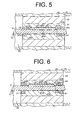
- annular dry bearings 60 are provided on the inner peripheral surface 44a of the guide member 44 adjacently to its front and rear ends, respectively.
- the dry bearings 60 are made of a solid lubricant, such as polytetrafluoroethylene, polyacetal, or polyimide, which has a friction coefficient which is smaller than that of metal.
- the dry bearings 60 are rotatable with the guide member 44 and rotatably support at their inner peripheral surfaces 60a the outer peripheral surface 31a of the drive shaft 31.
- the inner peripheral surfaces 60a of the dry bearings 60 and the outer peripheral surface 31 a of the drive shaft 31 cooperate to form a plain bearing
- the dry bearings 60 corresponds to a bearing member which is interposed between the outer peripheral surface 31a of the drive shaft 31 and the inner peripheral surface 44a of the guide member 44. Sliding resistance between the outer peripheral surface 31a of the drive shaft 31 and the inner peripheral surfaces 60a of the dry bearings 60 are reduced, thus the drive shaft 31 being smoothly rotated.
- the drive shaft 31 is rotated through the dry bearings 60 without direct sliding contact of the outer peripheral surface 31a with the inner peripheral surface 44a of the guide member 44.
- seizure of the outer peripheral surface 31a of the drive shaft 31 is prevented and the serviceable life of the electric motor 41 is extended.
- a lubricating oil may be filled in the groove 47.
- the dry bearings 60 serves also to prevent the lubricating oil from leaking out of the electric motor 41.
- radial bearings 61 as a bearing member are provided between the inner peripheral surface 44a of the guide member 44 and the outer peripheral surface 31 a of the drive shaft 31 adjacently to the front and rear ends of the guide member 44, respectively-
- the radial bearings 61 support the drive shaft 31 so that the drive shaft 31 is rotatable relative to the guide member 44 (or the motor rotor 43) for a rotation angle of about 2 degrees.
- the radial bearings 61 are of grease-filled type. Namely, grease as lubricating oil is filled in the radial bearings 61 to maintain lubrication of the radial bearings 61, thus the drive shaft 31 being smoothly rotated.
- lip seals 63 as a seal member are interposed between the inner peripheral surface 44a of the guide member 44 and the outer peripheral surface 31 a of the drive shaft 31 adjacently to the front and rear ends of the guide member 44, respectively.
- the seal devices 63 prevent the lubricating oil, which is filled between the outer peripheral surface 31a of the drive shaft 31 and the inner peripheral surface 44a of the guide member 44, from leaking out of the electric motor 41.
- the groove 47 may be formed in the outer peripheral surface 31a of the drive shaft 31, the first portion 45a of the key 45 may be press-fitted in the inner peripheral surface 44a of the guide member 44, and the second portion 45b of the key 45 is inserted in the groove 47. In this case, as the motor rotor 43 is rotated, the key 45 is moved to collide against the first and second inner side surfaces 47A and 47B of the groove 47.
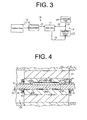
- the rotation angle for which the electric motor 41 rotates until the key 45 is brought into contact with the groove 47 may be a specific angle which is obtained by dividing 360 degrees by the number of the stator coils 42a, and the obtained specific angle may be used for the opening width of the groove 47.
- the motor rotor 43 is moved for the specfic angle for which the motor rotor is rotated by one time of energization of the electric motor 41, thereby allowing the key 45 to collide against the groove 47.
- the controllability of the electric motor 41 is improved.
- the guide member 44 may be removed and the drive shaft 31 may be inserted directly through the motor rotor 43 so that the drive shaft 31 is rotatable relative to the motor rotor 43.
- the inner peripheral surface of the motor rotor 43 corresponds to the inner peripheral surface of the electric motor 41 which faces the outer peripheral surface 31 a of the drive shaft 31.
- the key 45 may be provided in one of the outer peripheral surface 31a of the drive shaft 31 and the inner peripheral surface of the motor rotor 43, and the groove 47 may be formed in the other of the outer peripheral surface 31a of the drive shaft 31 and the inner peripheral surface of the motor rotor 43.
- alternate coil energization and de-energization may be repeated thereby to rotate the motor rotor 43 in the forward and reverse directions alternately.
- first and second inner side surfaces 47A and 47B of the groove 47 collide alternately against the first and second side surfaces 45A and 45B of the key 45.
- the two-lobe drive and driven rotors 39 and 40 of the electric roots pump 17 may be substituted with rotors each having three or more lobes.
- the electric roots pump may be of multi-stage type in which a plurality of the drive rotors 39 and a plurality of the driven rotors 40 are mounted and arranged on the drive shaft 31 and the driven shaft 35 in the axial direction thereof, respectively.
- the electric pump of the present invention is described as embodied for use in the electric roots pump 17 which has the drive rotor 39 and the driven rotor 40 as a rotor.
- the present invention may be applied to an electric screw pump which has screw rotors as a rotor.
- the guide member 44 is press-fitted in the motor rotor 43 in the above preferred embodiments.
- the guide member 44 may be fixed to the motor rotor 43 by any suitable means such as screw or rivet.
- first and second inner side surfaces 47A and 47B of the groove 47 and the first and second side surfaces 45A and 45B of the key 45 are formed flat and those flat surfaces collide against each other thereby to transmit torque.
- first and second inner side surfaces 47A and 47B of the groove 47 or the first and second side surfaces 45A and 45B of the key 45 may be formed in a spherical shape, while the other of the first and second inner side surfaces 47A and 47B and the first and second side surfaces 45A and 45B may be formed in a complementary concave shape which fits to the spherical shape.
- An electric pump for supplying a hydrogen gas to a fuel cell includes a rotary shaft rotatably inserted through an electric motor, a transmitting member provided on one of an outer peripheral surface of the rotary shaft and an inner peripheral surface of the electric motor so as to be rotatable therewith, and a groove formed in the other of the outer peripheral surface of the rotary shaft and the inner peripheral surface of the electric motor for the transmitting member to be inserted therein.
- the groove transmits a rotary torque of the electric motor to the rotary shaft by contacting an inner surface of the groove and the transmitting member and has an opening width along a rotary direction of the rotary shaft which is larger than the width of the transmitting member.
- the groove and the transmitting member produce an impact torque when the electric pump is started.
Landscapes
- Engineering & Computer Science (AREA)
- General Engineering & Computer Science (AREA)
- Mechanical Engineering (AREA)
- Chemical & Material Sciences (AREA)
- Life Sciences & Earth Sciences (AREA)
- Manufacturing & Machinery (AREA)
- Sustainable Development (AREA)
- Sustainable Energy (AREA)
- Power Engineering (AREA)
- Chemical Kinetics & Catalysis (AREA)
- Electrochemistry (AREA)
- General Chemical & Material Sciences (AREA)
- Fuel Cell (AREA)
- Applications Or Details Of Rotary Compressors (AREA)
- Compressor (AREA)
- Connection Of Motors, Electrical Generators, Mechanical Devices, And The Like (AREA)
Applications Claiming Priority (1)
| Application Number | Priority Date | Filing Date | Title |
|---|---|---|---|
| JP2006013082A JP4640190B2 (ja) | 2006-01-20 | 2006-01-20 | 水素循環用電動ポンプ |
Publications (2)
| Publication Number | Publication Date |
|---|---|
| EP1811181A1 true EP1811181A1 (fr) | 2007-07-25 |
| EP1811181B1 EP1811181B1 (fr) | 2009-03-18 |
Family
ID=37964020
Family Applications (1)
| Application Number | Title | Priority Date | Filing Date |
|---|---|---|---|
| EP07100734A Not-in-force EP1811181B1 (fr) | 2006-01-20 | 2007-01-18 | Pompe électrique pour circulation d'hydrogène |
Country Status (7)
| Country | Link |
|---|---|
| US (1) | US8491279B2 (fr) |
| EP (1) | EP1811181B1 (fr) |
| JP (1) | JP4640190B2 (fr) |
| KR (1) | KR100758171B1 (fr) |
| CN (1) | CN101004174A (fr) |
| DE (1) | DE602007000689D1 (fr) |
| TW (1) | TW200741101A (fr) |
Cited By (5)
| Publication number | Priority date | Publication date | Assignee | Title |
|---|---|---|---|---|
| WO2009082393A1 (fr) * | 2007-12-21 | 2009-07-02 | Utc Power Corporation | Libération d'un composant de pile à combustible gelé |
| FR2998339A1 (fr) * | 2012-11-19 | 2014-05-23 | Danfoss Commercial Compressors | Compresseur de refrigeration et procede pour assembler un tel compresseur de refrigeration |
| EP3229345A4 (fr) * | 2014-12-03 | 2018-03-28 | Nissan Motor Co., Ltd | Structure de rotor de machine électrique tournante |
| WO2020221478A1 (fr) * | 2019-05-01 | 2020-11-05 | Eaton Intelligent Power Limited | Système de pompe rge à rotors en porte-à-faux |
| US20230258179A1 (en) * | 2020-09-02 | 2023-08-17 | Eaton Intelligent Power Limited | Rear drive egr pump |
Families Citing this family (19)
| Publication number | Priority date | Publication date | Assignee | Title |
|---|---|---|---|---|
| JP4692299B2 (ja) | 2006-01-24 | 2011-06-01 | 株式会社豊田自動織機 | 電動ポンプ |
| JP5522158B2 (ja) * | 2011-02-08 | 2014-06-18 | 株式会社豊田自動織機 | 圧縮機 |
| CN102748285A (zh) * | 2012-04-11 | 2012-10-24 | 无锡市制冷设备厂有限责任公司 | 一种螺杆压缩机 |
| FR2998340A1 (fr) * | 2012-11-19 | 2014-05-23 | Danfoss Commercial Compressors | Compresseur a spirale a vitesse variable. |
| CN106130236A (zh) * | 2016-06-14 | 2016-11-16 | 浙江瑞翔机电科技股份有限公司 | 一种充气泵用电机 |
| CN106067702A (zh) * | 2016-06-14 | 2016-11-02 | 浙江瑞翔机电科技股份有限公司 | 充气泵用电机 |
| JP6822293B2 (ja) * | 2017-04-18 | 2021-01-27 | トヨタ自動車株式会社 | 燃料電池システム |
| DE102019100404B4 (de) | 2018-01-22 | 2023-06-22 | Kabushiki Kaisha Toyota Jidoshokki | Motorgetriebene Wälzkolbenpumpe |
| CN109595142B (zh) * | 2019-01-30 | 2021-02-23 | 安徽美芝制冷设备有限公司 | 压缩机及其转子装配结构、制冷设备 |
| CN112555150A (zh) * | 2019-09-10 | 2021-03-26 | 南昌海立电器有限公司 | 一种压缩机及其装配方法 |
| CN110566459B (zh) * | 2019-09-11 | 2024-07-09 | 烟台东德实业有限公司 | 一种氢循环泵总成 |
| JP7398343B2 (ja) * | 2020-06-26 | 2023-12-14 | 株式会社荏原製作所 | 樹脂モールドロータ、キャンドモータ、キャンドモータポンプ、ファンスクラバー、真空ポンプ装置 |
| CN114607597A (zh) * | 2020-12-04 | 2022-06-10 | 中国科学院沈阳科学仪器股份有限公司 | 一种真空泵内转子轴组件 |
| CN114135486B (zh) * | 2022-01-10 | 2024-04-02 | 江苏航空职业技术学院 | 一种平面磁力驱动氢气循环泵 |
| CN114135485B (zh) * | 2022-01-10 | 2024-04-19 | 江苏航空职业技术学院 | 一种环状磁力驱动氢气循环泵 |
| CN114776592A (zh) * | 2022-05-08 | 2022-07-22 | 烟台东德实业有限公司 | 一种包塑转子带破冰功能氢气循环泵 |
| CN114962266B (zh) * | 2022-05-08 | 2023-07-11 | 烟台东德实业有限公司 | 一种单向轴承型破冰氢气循环泵 |
| CN116480579B (zh) * | 2023-04-23 | 2024-08-13 | 烟台东德实业有限公司 | 一种氢气循环泵挖空破冰方法 |
| CN116576109A (zh) * | 2023-06-05 | 2023-08-11 | 烟台东德实业有限公司 | 一种燃料电池用氢气循环泵 |
Citations (7)
| Publication number | Priority date | Publication date | Assignee | Title |
|---|---|---|---|---|
| EP0474004A2 (fr) | 1990-09-07 | 1992-03-11 | Hanning Elektro-Werke GmbH & Co. | Moteur synchrone comportant un dispositif de démarrage |
| EP0723329A2 (fr) | 1995-01-19 | 1996-07-24 | ASKOLL S.p.A. | Dispositif de démarrage pour le rotor d'un moteur synchrone à aimant permanent |
| US5569022A (en) * | 1993-09-17 | 1996-10-29 | Sole S.P.A. | Self-unblocking motor-driven pump having last motion shaft coupling |
| EP1016786A2 (fr) | 1998-12-31 | 2000-07-05 | FAGOR, S.Coop | Accouplement pour la transmission de la rotation dans un moteur synchrone |
| US20050110446A1 (en) * | 2003-11-25 | 2005-05-26 | Masanao Kagami | System and method for starting pump |
| WO2006018620A1 (fr) * | 2004-08-19 | 2006-02-23 | The Boc Group Plc | Pompe à vide |
| DE102004060872A1 (de) * | 2004-12-17 | 2006-07-06 | Hanning Elektro-Werke Gmbh & Co. Kg | Synchronmotor mit Anlaufeinrichtung |
Family Cites Families (18)
| Publication number | Priority date | Publication date | Assignee | Title |
|---|---|---|---|---|
| US2140966A (en) * | 1936-07-08 | 1938-12-20 | Arthur A Nichols | Rotary mechanism |
| US2193408A (en) * | 1937-03-10 | 1940-03-12 | Allis Chalmers Mfg Co | Dynamo-electric machine |
| US2698911A (en) * | 1950-11-30 | 1955-01-04 | Edward J Schaefer | Submersible motor construction |
| US3001093A (en) * | 1956-08-30 | 1961-09-19 | North American Aviation Inc | Low speed synchronous motor |
| US2938131A (en) * | 1957-07-15 | 1960-05-24 | Smith Corp A O | Liquid filled submersible motor |
| JPH05306687A (ja) * | 1992-04-30 | 1993-11-19 | Suzuki Motor Corp | 回転式液体ポンプ |
| US5283469A (en) * | 1992-07-29 | 1994-02-01 | General Electric Company | Impact start assist for an electric motor |
| DE4432551A1 (de) * | 1994-09-13 | 1996-03-14 | Bayer Ag | Pumpe zur Förderung heißer, korrosiver Medien |
| US5684348A (en) * | 1996-02-28 | 1997-11-04 | Main; Louis | Automatic damping and transient supressing improvement in synchronous motors and generators |
| US5887982A (en) * | 1997-06-17 | 1999-03-30 | U.S. Filter Wastewater Group, Inc. | Bearing assembly for use with a submerged apparatus and method for performing maintenance thereon |
| JP3752996B2 (ja) | 2000-11-15 | 2006-03-08 | 株式会社デンソー | 回転式ポンプ |
| JP2003155409A (ja) | 2001-11-22 | 2003-05-30 | Daiso Co Ltd | 加硫用ゴム組成物およびその加硫ゴム材料 |
| WO2004018879A1 (fr) * | 2002-08-20 | 2004-03-04 | Ebara Corporation | Pompe a vide et procede de demarrage de cette pompe |
| JP2004278502A (ja) * | 2003-01-24 | 2004-10-07 | Toyota Industries Corp | 多段ギヤポンプ |
| JP4658245B2 (ja) | 2003-05-29 | 2011-03-23 | 株式会社日立製作所 | スクロール式流体機械 |
| KR100556404B1 (ko) * | 2003-12-17 | 2006-03-03 | 엘지전자 주식회사 | 이중용량 로터리 압축기 |
| US20070132330A1 (en) * | 2005-12-12 | 2007-06-14 | Fei Renyan W | Fan assemblies employing LSPM motors and LSPM motors having improved synchronization |
| JP4692299B2 (ja) * | 2006-01-24 | 2011-06-01 | 株式会社豊田自動織機 | 電動ポンプ |
-
2006
- 2006-01-20 JP JP2006013082A patent/JP4640190B2/ja not_active Expired - Fee Related
- 2006-10-23 TW TW095138933A patent/TW200741101A/zh unknown
- 2006-11-03 KR KR1020060108113A patent/KR100758171B1/ko not_active Expired - Fee Related
-
2007
- 2007-01-18 EP EP07100734A patent/EP1811181B1/fr not_active Not-in-force
- 2007-01-18 DE DE602007000689T patent/DE602007000689D1/de active Active
- 2007-01-18 US US11/655,812 patent/US8491279B2/en not_active Expired - Fee Related
- 2007-01-19 CN CNA2007100040278A patent/CN101004174A/zh active Pending
Patent Citations (8)
| Publication number | Priority date | Publication date | Assignee | Title |
|---|---|---|---|---|
| EP0474004A2 (fr) | 1990-09-07 | 1992-03-11 | Hanning Elektro-Werke GmbH & Co. | Moteur synchrone comportant un dispositif de démarrage |
| US5569022A (en) * | 1993-09-17 | 1996-10-29 | Sole S.P.A. | Self-unblocking motor-driven pump having last motion shaft coupling |
| EP0723329A2 (fr) | 1995-01-19 | 1996-07-24 | ASKOLL S.p.A. | Dispositif de démarrage pour le rotor d'un moteur synchrone à aimant permanent |
| EP1016786A2 (fr) | 1998-12-31 | 2000-07-05 | FAGOR, S.Coop | Accouplement pour la transmission de la rotation dans un moteur synchrone |
| US20050110446A1 (en) * | 2003-11-25 | 2005-05-26 | Masanao Kagami | System and method for starting pump |
| JP2005155409A (ja) * | 2003-11-25 | 2005-06-16 | Toyota Industries Corp | ルーツ型圧縮機の起動装置及び方法 |
| WO2006018620A1 (fr) * | 2004-08-19 | 2006-02-23 | The Boc Group Plc | Pompe à vide |
| DE102004060872A1 (de) * | 2004-12-17 | 2006-07-06 | Hanning Elektro-Werke Gmbh & Co. Kg | Synchronmotor mit Anlaufeinrichtung |
Cited By (9)
| Publication number | Priority date | Publication date | Assignee | Title |
|---|---|---|---|---|
| WO2009082393A1 (fr) * | 2007-12-21 | 2009-07-02 | Utc Power Corporation | Libération d'un composant de pile à combustible gelé |
| US8486573B2 (en) | 2007-12-21 | 2013-07-16 | Utc Power Corporation | Freeing a frozen fuel cell component |
| FR2998339A1 (fr) * | 2012-11-19 | 2014-05-23 | Danfoss Commercial Compressors | Compresseur de refrigeration et procede pour assembler un tel compresseur de refrigeration |
| EP3229345A4 (fr) * | 2014-12-03 | 2018-03-28 | Nissan Motor Co., Ltd | Structure de rotor de machine électrique tournante |
| WO2020221478A1 (fr) * | 2019-05-01 | 2020-11-05 | Eaton Intelligent Power Limited | Système de pompe rge à rotors en porte-à-faux |
| US11840992B2 (en) | 2019-05-01 | 2023-12-12 | Eaton Intelligent Power Limited | EGR pump system with overhung rotors |
| US20230258179A1 (en) * | 2020-09-02 | 2023-08-17 | Eaton Intelligent Power Limited | Rear drive egr pump |
| US12338817B2 (en) * | 2020-09-02 | 2025-06-24 | Eaton Intelligent Power Limited | Rear drive EGR pump |
| US20250297609A1 (en) * | 2020-09-02 | 2025-09-25 | Eaton Intelligent Power Limited | Rear drive egr pump |
Also Published As
| Publication number | Publication date |
|---|---|
| KR20070077043A (ko) | 2007-07-25 |
| KR100758171B1 (ko) | 2007-09-12 |
| US8491279B2 (en) | 2013-07-23 |
| US20070177999A1 (en) | 2007-08-02 |
| CN101004174A (zh) | 2007-07-25 |
| EP1811181B1 (fr) | 2009-03-18 |
| JP2007192181A (ja) | 2007-08-02 |
| JP4640190B2 (ja) | 2011-03-02 |
| DE602007000689D1 (de) | 2009-04-30 |
| TW200741101A (en) | 2007-11-01 |
Similar Documents
| Publication | Publication Date | Title |
|---|---|---|
| US8491279B2 (en) | Electric pump for hydrogen circulation | |
| JP2616922B2 (ja) | スクリユー圧縮機 | |
| US4362480A (en) | Rotary roller vane pump made of specific materials | |
| JP2024507034A (ja) | ロータ組立体、圧縮機及び空気調和機 | |
| US7700207B2 (en) | Turbocompressor shutdown mechanism | |
| JP2009250215A (ja) | 液体供給装置 | |
| US7980830B2 (en) | Electric pump | |
| KR102864623B1 (ko) | 스크롤 압축기 | |
| US8419286B2 (en) | Hermetic compressor | |
| CN107893758B (zh) | 涡旋压缩机及具有其的空调器 | |
| EP1770811A2 (fr) | Système de pile à combustible avec compresseur et turbine couplés | |
| US9435337B2 (en) | Scroll compressor | |
| JP2006132403A (ja) | スクロール型圧縮機 | |
| CN118167541A (zh) | 一种分离式导轨及应用分离式导轨的内曲线径向柱塞马达 | |
| JP4730974B2 (ja) | ベーンタイプ機械およびベーンタイプ機械を使用しながら廃熱を利用する方法 | |
| US20080213116A1 (en) | Multi-Stage Rotary Compressor | |
| JP2006177299A (ja) | 電動ポンプ | |
| JP2007211865A (ja) | クリープ防止転がり軸受 | |
| JP2009257161A (ja) | タイミングギアを含む駆動力伝達機構 | |
| JP2010038120A (ja) | 流体機械 | |
| JPH11257268A (ja) | ヘリカルブレード式コンプレッサ | |
| JP2005147059A (ja) | 燃料電池用圧縮機 | |
| JP2003202029A (ja) | 転がり軸受装置 | |
| JP2008014283A (ja) | スクロール圧縮機 | |
| JP2004169717A (ja) | 転がり支持装置 |
Legal Events
| Date | Code | Title | Description |
|---|---|---|---|
| PUAI | Public reference made under article 153(3) epc to a published international application that has entered the european phase |
Free format text: ORIGINAL CODE: 0009012 |
|
| 17P | Request for examination filed |
Effective date: 20070118 |
|
| AK | Designated contracting states |
Kind code of ref document: A1 Designated state(s): AT BE BG CH CY CZ DE DK EE ES FI FR GB GR HU IE IS IT LI LT LU LV MC NL PL PT RO SE SI SK TR |
|
| AX | Request for extension of the european patent |
Extension state: AL BA HR MK YU |
|
| AKX | Designation fees paid |
Designated state(s): DE FR GB |
|
| 17Q | First examination report despatched |
Effective date: 20080612 |
|
| GRAP | Despatch of communication of intention to grant a patent |
Free format text: ORIGINAL CODE: EPIDOSNIGR1 |
|
| GRAS | Grant fee paid |
Free format text: ORIGINAL CODE: EPIDOSNIGR3 |
|
| GRAA | (expected) grant |
Free format text: ORIGINAL CODE: 0009210 |
|
| AK | Designated contracting states |
Kind code of ref document: B1 Designated state(s): DE FR GB |
|
| REG | Reference to a national code |
Ref country code: GB Ref legal event code: FG4D |
|
| REF | Corresponds to: |
Ref document number: 602007000689 Country of ref document: DE Date of ref document: 20090430 Kind code of ref document: P |
|
| PLBE | No opposition filed within time limit |
Free format text: ORIGINAL CODE: 0009261 |
|
| STAA | Information on the status of an ep patent application or granted ep patent |
Free format text: STATUS: NO OPPOSITION FILED WITHIN TIME LIMIT |
|
| 26N | No opposition filed |
Effective date: 20091221 |
|
| PGFP | Annual fee paid to national office [announced via postgrant information from national office to epo] |
Ref country code: DE Payment date: 20140115 Year of fee payment: 8 |
|
| PGFP | Annual fee paid to national office [announced via postgrant information from national office to epo] |
Ref country code: FR Payment date: 20140108 Year of fee payment: 8 |
|
| PGFP | Annual fee paid to national office [announced via postgrant information from national office to epo] |
Ref country code: GB Payment date: 20140115 Year of fee payment: 8 |
|
| REG | Reference to a national code |
Ref country code: DE Ref legal event code: R119 Ref document number: 602007000689 Country of ref document: DE |
|
| GBPC | Gb: european patent ceased through non-payment of renewal fee |
Effective date: 20150118 |
|
| PG25 | Lapsed in a contracting state [announced via postgrant information from national office to epo] |
Ref country code: DE Free format text: LAPSE BECAUSE OF NON-PAYMENT OF DUE FEES Effective date: 20150801 Ref country code: GB Free format text: LAPSE BECAUSE OF NON-PAYMENT OF DUE FEES Effective date: 20150118 |
|
| REG | Reference to a national code |
Ref country code: FR Ref legal event code: ST Effective date: 20150930 |
|
| PG25 | Lapsed in a contracting state [announced via postgrant information from national office to epo] |
Ref country code: FR Free format text: LAPSE BECAUSE OF NON-PAYMENT OF DUE FEES Effective date: 20150202 |