EP1811191B1 - Agencement de joint de transmission articulé - Google Patents
Agencement de joint de transmission articulé Download PDFInfo
- Publication number
- EP1811191B1 EP1811191B1 EP07009454A EP07009454A EP1811191B1 EP 1811191 B1 EP1811191 B1 EP 1811191B1 EP 07009454 A EP07009454 A EP 07009454A EP 07009454 A EP07009454 A EP 07009454A EP 1811191 B1 EP1811191 B1 EP 1811191B1
- Authority
- EP
- European Patent Office
- Prior art keywords
- bearing
- universal joint
- joint arrangement
- journal
- spring unit
- Prior art date
- Legal status (The legal status is an assumption and is not a legal conclusion. Google has not performed a legal analysis and makes no representation as to the accuracy of the status listed.)
- Active
Links
Images



Classifications
-
- F—MECHANICAL ENGINEERING; LIGHTING; HEATING; WEAPONS; BLASTING
- F16—ENGINEERING ELEMENTS AND UNITS; GENERAL MEASURES FOR PRODUCING AND MAINTAINING EFFECTIVE FUNCTIONING OF MACHINES OR INSTALLATIONS; THERMAL INSULATION IN GENERAL
- F16C—SHAFTS; FLEXIBLE SHAFTS; ELEMENTS OR CRANKSHAFT MECHANISMS; ROTARY BODIES OTHER THAN GEARING ELEMENTS; BEARINGS
- F16C21/00—Combinations of sliding-contact bearings with ball or roller bearings, for exclusively rotary movement
- F16C21/005—Combinations of sliding-contact bearings with ball or roller bearings, for exclusively rotary movement the external zone of a bearing with rolling members, e.g. needles, being cup-shaped, with or without a separate thrust-bearing disc or ring, e.g. for universal joints
-
- F—MECHANICAL ENGINEERING; LIGHTING; HEATING; WEAPONS; BLASTING
- F16—ENGINEERING ELEMENTS AND UNITS; GENERAL MEASURES FOR PRODUCING AND MAINTAINING EFFECTIVE FUNCTIONING OF MACHINES OR INSTALLATIONS; THERMAL INSULATION IN GENERAL
- F16D—COUPLINGS FOR TRANSMITTING ROTATION; CLUTCHES; BRAKES
- F16D3/00—Yielding couplings, i.e. with means permitting movement between the connected parts during the drive
- F16D3/16—Universal joints in which flexibility is produced by means of pivots or sliding or rolling connecting parts
- F16D3/26—Hooke's joints or other joints with an equivalent intermediate member to which each coupling part is pivotally or slidably connected
- F16D3/38—Hooke's joints or other joints with an equivalent intermediate member to which each coupling part is pivotally or slidably connected with a single intermediate member with trunnions or bearings arranged on two axes perpendicular to one another
- F16D3/382—Hooke's joints or other joints with an equivalent intermediate member to which each coupling part is pivotally or slidably connected with a single intermediate member with trunnions or bearings arranged on two axes perpendicular to one another constructional details of other than the intermediate member
- F16D3/385—Bearing cup; Bearing construction; Bearing seal; Mounting of bearing on the intermediate member
-
- F—MECHANICAL ENGINEERING; LIGHTING; HEATING; WEAPONS; BLASTING
- F16—ENGINEERING ELEMENTS AND UNITS; GENERAL MEASURES FOR PRODUCING AND MAINTAINING EFFECTIVE FUNCTIONING OF MACHINES OR INSTALLATIONS; THERMAL INSULATION IN GENERAL
- F16C—SHAFTS; FLEXIBLE SHAFTS; ELEMENTS OR CRANKSHAFT MECHANISMS; ROTARY BODIES OTHER THAN GEARING ELEMENTS; BEARINGS
- F16C2361/00—Apparatus or articles in engineering in general
- F16C2361/41—Couplings
Definitions
- the invention relates to a universal joint arrangement, in detail with the features of the preamble of claim 1.
- Universal joint arrangements in particular the bearing systems for supporting pins of a journal cross in joint forks for use in cardan shafts are known in a variety of designs for a variety of application examples.
- Embodiments of universal joint arrangements for propeller shafts which comprise at least one spider, which is mounted in at least one yoke.
- the yoke itself can be made in one or two parts.
- To connect the journal cross in the yoke a corresponding bearing arrangement is provided in each case for the individual pin.
- the bearing assembly comprises at least one radial bearing and a thrust bearing.
- For the arrangement of the thrust bearing there are a variety of possibilities, but taking into account the deformations occurring during operation of the propeller shaft, a corresponding structural design of the individual elements of the storage takes place.
- the problem of such a bearing arrangement is that the individual bearings in addition to a high base torque in addition by high torque shocks and simultaneous lateral acceleration, especially when used in rolling mill drives, are claimed.
- the elastic deformations also result in relative movements between the pin and the fork bore in the axial direction. If these relative movements are hindered by too rigid bearing embedding, high constraining forces and thus high loads result in the rolling contact of the axial bearings. This results in a segment of the thrust bearing to high edge stresses and in the opposite segment to lift the rollers. The unequal load leads to a reduction in capacity.
- the structural design, in particular the design of the individual components, is always matched to the possibly occurring deformation paths. It is not possible to provide a satisfactory construction regardless of the knowledge of these influences.
- a universal joint arrangement comprises two mutually offset by 90 ° joint forks. In these a cross is stored.
- Each yoke has for this purpose a flange part and two bearing parts, wherein the pins lying on a common axis of the journal cross are respectively stored in the two bearing parts in a bearing bore.
- a corresponding bearing system or a bearing arrangement is provided for each pin, which comprises at least one radial bearing and a thrust bearing, wherein the thrust bearing is arranged either in the region of the journal root or on the journal end side.
- the thrust bearing can be designed as a plain bearing or roller bearings. This is supported according to the invention via a Compensation element in the form of a partially elastic spring unit 2 at the spider or the yoke, at least indirectly from, ie directly or indirectly. Intermediate can thus be, for example, a pressure ring.
- Partially elastic means that the compensating element under high loads compensates for the deformations of the bearing environment caused by the constraining forces due to the circumferential forces. Partial elastic also means that the compensation element in the areas which are in installation position in areas of low deformation, is made stiff and elastic in the areas of higher deformation: The partial elasticity thus includes areas of different stiffness or different elasticities. This ensures that the system can adjust elastically under load, but in the load-free state is given an axially rigid transmission. These are generated by circumferentially adjacently arranged region of different materials or combinations of materials, the materials differ in terms of their modulus of elasticity.
- the compensating element can be produced by the integral connection of individual elements made of different materials or material combinations with different stiffnesses.
- the different elasticities can be produced by changing the cross-sectional geometry.
- the partially elastic spring unit is designed such that it is preferably designed as an annular element or annular element with any inner contour, wherein the elastic region with a modulus of elasticity between 5000 to 50,000 N / mm 2 , preferably 5000 to 20,000 N / mm 2 is executed.
- the annular element in the circumferential direction in Regions of higher stiffness and lower stiffness divided.
- the stiffness differences can be realized in addition by an elastic shaping.
- these areas are characterized by the use of materials or combinations of materials with different E-modules.
- the areas in installation position, which counteract during torque transmission of a greater natural deformation and thus subject to a higher load, are characterized in particular by smaller cross-sectional sizes and softer materials than the regions of higher rigidity.
- the cross-sectional enlargement takes place essentially in the installed position in the vertical direction, d. H. for the annular element considered in the height direction and optionally additionally in the thickness direction.
- a rectangular cross-section or a cross-sectional geometry with at least one flat surface, preferably two oppositely arranged surfaces is selected to ensure a flat concerns according to the selected material of the annular element of the elastic spring unit.
- the annular element is characterized at least by an outer diameter.
- the inner contour may be characterized by one or more different inner diameter ranges or any geometry. The latter variant comes into play when a bearing-oriented centering is desired by a correspondingly complementary contour on the connecting elements, which predetermines the installation position.
- the elastic spring unit in particular the annular element, can consist of a steel, in particular spring steel, tempered steel, etc., an elastomer or a plastic (elastomer, rubber) or a rubber-elastic element. It is crucial that under stress always a positive connection is generated, with a complete positive connection between the axial bearing facing end side of the elastic spring unit and the thrust bearing supporting element or the thrust bearing itself is given.
- the annular element is constructed symmetrically, so that the installation can be carried out regardless of the direction of rotation of the coupled with the spider shaft.
- the annular element of the elastic spring unit is divided in a view from above, starting from the theoretical center in the radial direction into two symmetrical ring segments. Starting from a first axis of symmetry extending from the center, in each case a first support region extends on both sides in the circumferential direction in the direction of a further axis of symmetry extending through the center point perpendicular to the axis of symmetry. This first support region is characterized by a constant cross-sectional profile. The first one is followed by a second area, which is referred to as the second partially active support area.
- the change in cross section takes place uniformly over the entire width or thickness of the annular element and also in the vertical direction in each case over a partial area in the circumferential direction. Only the transitions between the different cross sections are preferably not abrupt, but rather by a uniform cross-sectional change in the direction of the respective reduced or enlarged cross section.
- This can be achieved especially when using a thrust bearing in the form of a rolling bearing a good contact pattern.
- this also applies to axial bearings in plain bearing design, whose sliding surfaces are loaded more uniformly.
- first support regions and the second partially active support regions forming different cross-sectional areas exist a variety of ways, which may differ in terms of extent, preferably in the circumferential direction.
- the extension takes place in each case on both sides of a first axis of symmetry at the same distance from this axis of symmetry in the circumferential direction, d. H. a segment area is provided on both sides of a first axis of symmetry at a certain distance from the axis of symmetry with the enlarged cross section.
- This then also applies to the second partially active support area.
- This is likewise arranged symmetrically with respect to the first axis of symmetry and adjoins the or the first support areas.
- the subdivision is quadrant wise.
- the symmetrical design allows the same effect even in reversing operation.
- the solution according to the invention can be used both for designs with axial bearings arranged in the region of the journal root and with axial bearings arranged in the region of the journal end side.
- the thrust bearing disc-shaped element is supported in training as a sliding bearing or an axial bearing raceway forming element either directly or via other elements with the interposition of the partially elastic spring unit on the journal root.
- the part-elastic element is provided between thrust bearing and spigot root.
- another element for example in the form of a pressure ring, is provided between the thrust bearing or the element forming a running surface or a sliding surface and the spigot root, the thrust bearing extending over the thrust bearing partially elastic spring unit is supported on this thrust ring and on this at the spigot root.
- the respective other running surface or sliding surface is supported at least indirectly on the yoke. The support takes place for example via the radial bearing outer ring.
- the compensation element in the form of the partially elastic spring unit is substantially annular, wherein the desired inner bearing contour is not characterized by a diameter, but by other geometries that interact with complementary geometries in the form of projections on the connection element.
- the solution according to the invention is conceivable for universal joint arrangements with a closed joint fork design, ie bearing bore in the form of a blind bore as well as passage opening. Furthermore, it is irrelevant whether the yoke is in split design. Furthermore, the solution according to the invention can be applied to universal joint arrangements with journal crosses with journal axes arranged in one plane or else journal crosses with journal axes arranged offset in parallel planes.
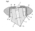
- FIG. 5 illustrated for clarity in greatly exaggerated presentation of the solution of the invention underlying problem of the effect of deformations on the bearing system of a spider 3 'a yoke 6' based on a section of an axial section through the spider 3 '.
- the storage system 10 ' comprises a radial bearing 13'. In the case shown, the inner race of the rolling elements 15 'of the radial bearing 13' from the outer periphery 16 'of the pin 4' is formed.
- the outer tread is formed by a bearing bush 41 '.
- the circumferential force causes an uneven loading of the radial bearing 13 ', ie in the direction of rotation very high edge stresses and on the opposite side a game between the rolling elements 15' and the connecting elements bearing bush 45 'or pin 4'.
- This also applies analogously to a thrust bearing, not shown here in detail, which according to the embodiment of FIG. 1 for example, between pin end face 36 'and inner circumference of the bearing bush 41' would be arranged. This would also be charged unevenly.
- FIG. 1 A illustrates in a schematically simplified representation of a section of an axial section through a universal joint arrangement 1, the integration of an inventively designed compensation element in the form of a partially elastic spring unit.
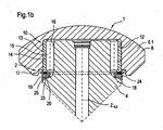
- FIG. 1b clarifies a section FIG. 1 a.
- the universal joint arrangement 1 comprises a spider 3, which with its staggered by 180 ° to each other arranged pins 4 and 5 in a yoke 6, comprising a flange 7 and two bearing parts 8 and 9 in the bearing parts 8 and 9 respectively via a bearing system 10 and 11 is stored.
- the two pins 4 and 5 are characterized by a common pin axis Z 4 , 5 .
- the journal cross 3 further comprises 90 ° offset from the pins 4 and 5 arranged pins which are mounted in a further joint fork, not shown here, wherein the yoke also comprises a flange and two bearing parts and stored the pins in the bearing parts via a corresponding storage system are.
- the yoke 6 is preferably designed in two parts. The division takes place in the flange 7, wherein the individual yoke halves 6.1 and 6.2 are then characterized by a flange 7.1 and 7.2 and each yoke half 6.1 and 6.2 comprise a bearing part.
- the yoke half 6.2 is shown in the form of the bearing part 9.
- the storage in the bearing parts 8 and 9 takes place in bearing bores, shown here by way of example only for the yoke half 6.1, in particular the bearing part 8.
- the bearing bore is designated by 12.
- the pins 4 and 5, which are mounted offset by 90 ° relative to the pivots 4 and 5 mounted in the yoke 6, are mounted, as already stated, in a further yoke (not shown here in detail).
- the yoke is coupled, for example, with a machine part of the drive side, not shown here and the joint fork, not shown here for the other pin of the spider 3 with a machine part of the output side.
- the journal axes Z 4, 5 and the journal axis Z of the pegs, not shown here, can be arranged as shown in one plane or in two mutually offset parallel planes.
- the single bearing system 10 comprises a radial bearing 13.
- the radial bearing 13 is preferably designed as a rolling bearing. This includes, for example, an outer ring 14 and rolling elements 15.
- the inner running surface for the rolling elements 15 is formed, for example, by the outer circumference 16 of the journal 4 mounted in the bearing part 8.
- the bearing system 10 comprises a thrust bearing 17.
- the thrust bearing 17 is arranged according to a first embodiment in the region of the journal root 18 of the pin 4. This can be designed as a rolling bearing or, for example, as a sliding bearing.
- the thrust bearing 17 is designed as a sliding bearing 19.
- the sliding bearing 19 comprises a disc-shaped element 20, which forms sliding pairings with the connection elements.
- the individual sliding surfaces forming elements 21 and 22 of the sliding pair 20, for example, from the outer ring 14 of the radial bearing 13 and the disk-shaped element 20 are formed.
- the disk-shaped element 20 is supported in the illustrated case on a pressure ring 23 via an at least partially elastic spring unit 2 on the spider 3, in particular on the pin 4. Conceivable would be the formation of the thrust bearing 17 as a rolling bearing.
- this rolling element would comprise, which is directed to an axis of articulation G, under which the axis is to be understood by the point of intersection of the journal axes Z 4,5 and Z, directed end face 24 of Support outer ring 14 of the radial bearing 13.
- end face 24 of the outer ring 14 of the radial bearing 13 directly form the outer raceway for the rolling elements of the thrust bearing 17. It is also conceivable that this end face 24 forms the support surface for the tread forming element.
- the inner running surface is aligned in the direction of the end face 25 of the pin 4 against this when viewed from the hinge axis G and can then be formed directly from the pressure ring 23 or a separate, a tread forming element, which is supported on the pressure ring 23.
- a centering unit 26 which is formed for example by a seal holder which is secured to the pin 4 and the pin 3. It is crucial that a centering with respect to the pin 4 takes place in the circumferential direction.
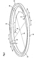
- the concrete embodiment of the partially elastic spring unit 2 is exemplary in the FIG. 2 played. This illustrates a perspective view with dash-dotted representation of the cross-sectional profiles. From the FIG. 2 is seen that the partially elastic spring unit 2 is formed as an annular element 28. Depending on the choice of material, this is made of a spring steel or as an elastomer or rubber-elastic element. It is crucial that the rubber-shaped element of its choice of material already has an elasticity which is characterized by an E-modulus in the range of 5000 to 50,000 N / mm 2 , preferably 5000 to 20,000 N / mm 2 .
- the partially elastic spring unit 2 is characterized by at least two regions with different cross sections.
- the partially elastic spring unit 2 is designed such that the areas of different cross-sections are arranged symmetrically, so that in the installation position in a universal joint arrangement 1, the function is ensured regardless of the direction of rotation of the universal joint arrangement 1. In idle, ie unloaded state, this is free of play. When loaded, a partially elastic positive connection is achieved.
- the partially elastic spring unit 2 based on a through the theoretical center M extending first Symmetrical line S D , two symmetrically arranged to each other areas 29 and 30, which form the form-fitting conforming support areas or support areas for the thrust bearing 17, in particular the sliding surfaces forming elements 21 and 22 of the thrust bearing 17 in the loaded state under the action of the circumferential force.
- support regions 29 and 30 are arranged symmetrically to each other and executed identical in terms of the geometry of the cross section.
- the support regions 29 and 30 extend in the circumferential direction of the partially elastic spring unit 2, preferably at a certain distance c viewed in the circumferential direction of the line of symmetry S D.
- the design of the support regions 29, 30 also has a symmetrical structure to a perpendicular to the axis of symmetry S D passing through the center axis S DS .
- These support areas 29 and 30 are also referred to as partially active support areas.
- support areas 31 and 32 are provided. These extend uniformly in the circumferential direction of the elastic spring unit 2 viewed from the line of symmetry S DS over a dimension a.
- the transition to the regions 29 and 30 subjected to greater stress takes place.
- the support regions 31 and 32 are in this case opposite the partially active regions 29 and 30 respectively by a cross-sectional reinforcement, in particular Height direction of the partially elastic spring unit 2, characterized. That is, the thickness dimensions are larger in this area. This is true at least for the height dimension as well as for the width dimension d in these areas.
- the dimensions characterizing the cross section are greater in the height direction h than in the regions 29 and 30, which are likewise arranged symmetrically with respect to the axis of symmetry S D.
- the elastic spring unit 2 is designed such that it must be installed only with a view to a centering in the circumferential direction, but not with respect to the arrangement or orientation of the end faces 33 and 34.
- Supporting areas 29 and 30 are each arranged in the circumferential direction, ie the direction of rotation of the spider 3, ie the axis of symmetry S D lies in a plane which by the pin axis Z 4 , 5 and z is perpendicular to this and to the hinge axis G and the pin Z axis 4 , 5 and the pin axis is perpendicular to this arranged pin.
- the vertical S DS to the axis of symmetry S D of the partially elastic spring unit 2 extends perpendicular to the plane described by the pin and Z and Z 4 , 5 level.
- the axial forces resulting from the transverse acceleration, which in the direction of the journal axis Z 4.5 away from the joint axis G, here, for example, in the direction of the yoke half 6.2, to a load of lying in this direction thrust bearing 17 and to relieve the in Zapfenachsraum lead against the direction of action of the axial forces on the side of the yoke half 6.1 lying thrust bearing 17.
- the unloaded bearing can also be referred to as a passive bearing and the loaded bearing as an active bearing in this operating condition.
- the deformation of the torque-transmitting components of a universal joint arrangement 1 in the circumferential direction of the force is so extreme that it comes in storage to a non-uniform force distribution and only a fraction of the possible load rating is used.
- the missing plane parallelism of the thrust bearing races or sliding surfaces usually causes premature fatigue or wear of these and when using rolling plastic deformation with its consequences.
- the guaranteed dynamic and static load capacities of the bearings are guaranteed by the bearing production only in a very rigid bearing connection construction.
- the partially elastic spring unit 2 is integrated so that it is always given under load.
- the solution according to the invention is characterized in that the partially elastic spring unit 2 is almost free of play at idle and allows a partially elastic flow of form.
- the bearing ratio is increased due to the reinforcement of the support areas in the areas of high load and the influence of the circumferential force. In the areas where the deformation is small, a rigid design is provided, while in areas where the deformation occurs, a soft solution is provided.
- the support areas 29 and 30 are arranged in the circumferential direction in the areas of high axial forces.
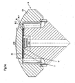
- FIG. 3a illustrates a first embodiment of the arrangement of the compensating element in the form of partially elastic spring unit 2 for an arrangement of the thrust bearing 17 on the journal end 36.
- the thrust bearing 17, in particular this forming disc-shaped element 20, arranged on the journal end side that this with its sliding surface 38.1 rests against the journal end face 36.
- the other sliding surface 38.2 is supported on the compensating element 2.
- the support then takes place via the compensating element in the form of the partially elastic spring unit 2 and a centering element 39 on the inner circumference 40 of the outer ring 14 of the radial bearing forming bush 41. About this occurs when installed in the yoke 6, the support on this.
- the centering element 39 is embodied here as a disk-shaped element which has a projection 42 which extends into the space 43 formed by the annular element in the form of the partially elastic spring unit 2 and preferably flat against the inner contour 44 of the partially elastic spring unit 2, preferably under play.
- the outer diameter d A39 is selected such that it corresponds to the outer diameter d A 17 of the thrust bearing. This applies analogously also for the outer diameter d A2 of the partially elastic spring unit 2.
- the projection 42 is characterized by a width B. This extends over the entire extent of the centering element 39, preferably along the coincident in the installed position with the axis of symmetry S DS of the partially elastic spring element symmetry axis S DS .
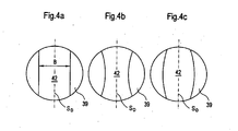
- FIGS. 4a to 4c illustrate possible embodiments for the realization of the centering function.
- the centering element 39 can be formed by a separate, preferably circular element or tap directly from the bearing connection element yoke. These have support areas in the form of projections 42, which cooperate by cooperating with complementary recesses or a complementary design of the inner contour of the compensation elements 2. It can be seen that the support region preferably extends in each case over the entire extent parallel to the axis of symmetry S D.
- the FIG. 4a illustrates a version with constant width B
- FIG. 4b a version with concave
- Figure 4c a version with convex geometry reflects. Other geometries are conceivable.
- FIG. 3b illustrates an embodiment according to FIG. 3a However, wherein the thrust bearing 17 via the partially elastic spring unit 2 and the centering element 39 directly on the yoke 6, in particular the bearing part 8, is supported. Again, the sliding surface 38 is located directly on the journal end 36. The opposite sliding surface is supported directly via the spring element 2 the yoke 6, in particular the bearing part 8.1, from interposed or executed in one piece with this is a centering element 39.
- the outer diameter d A39 of the centering element is adapted to the inner diameter d i12 of the bearing bore.
- the centering element 39 is provided with a projection 42 which is not rotationally symmetrical, but allows a bearing orientation of the compensating element in the form of partially elastic spring unit 2.
- the projection 42 can, as already for the FIG. 3a executed, with the same cross section over the entire extension along an axis of symmetry of the centering element 39 are executed. It is also conceivable embodiment with any geometry, such as a convex or concave configuration or an embodiment in the form of a polygon.
- the centering element 39 is arranged between the yoke 6, in particular the bearing part 8.1 and the compensating element.
- Figure 3c an embodiment according to FIG. 3b with rotationally symmetrical projection 42. This is characterized by a diameter d A39-42 .
- FIG. 1 illustrates the 3d figure an alternative arrangement of the partially elastic spring unit 2.
- This is arranged between the centering element 39 and the bearing part 8.1.
- the 3d figure illustrates an embodiment of a centering element 39 with non-rotationally symmetrical projection 42. This is characterized by a width B viewed over the entire diameter.
- the centering element is designed as a disk-shaped element with a small thickness d.
- FIG. 3e illustrates a further embodiment of the arrangement of the thrust bearing 17 on the journal end 36.
- This is based on the partially elastic spring unit 2 on the journal end 36 from.
- the execution according to 3d figure is free of a separate centering element. This centering function is taken over by the pin, in particular a corresponding configuration of the pin end face 36.
- a circular projection 42 is formed.
- FIG. 3e an embodiment according to 3d figure with centering element, this being formed directly from the yoke 6, in particular the bearing part 8.1.
- the projection 42 is here incorporated directly into the yoke half or the bearing part 8.1 by appropriate design of the bearing bore.
- the projection 42 is characterized by a circular cross-section.
- FIGS. 3a to 3e exemplify ways of arranging the individual elements of the thrust bearing 17 and the connecting elements to each other, in particular with the interposition of a. These possibilities are examples.
- the solution according to the invention is not limited to this. Furthermore, any sequence of centering element, compensation element and thrust bearing is possible.
- cross sections are selected which are characterized by the formation of planar surfaces. This means that preferably rectangular or square cross sections are used. Only the transition areas are then characterized by a different cross-sectional configuration.
Landscapes
- Engineering & Computer Science (AREA)
- General Engineering & Computer Science (AREA)
- Mechanical Engineering (AREA)
- Support Of The Bearing (AREA)
- Measuring Pulse, Heart Rate, Blood Pressure Or Blood Flow (AREA)
- Headphones And Earphones (AREA)
- Vibration Prevention Devices (AREA)
Claims (25)
- Agencement (1) d'un joint de cardan
avec un bloc croisillon (3) monté dans deux fourchettes (6) décalées de 90° l'une par rapport à l'autre ;
chaque fourchette du joint comprenant une partie formant bride (7) et deux parties formant palier (8, 9), chaque partie formant palier (8, 9) comportant un trou dans lequel sont portées les fusées du bloc croisillon (3);
chaque fusée (4, 5) étant portée au moyen d'un agencement de roulements (10, 11) ;
l'agencement de roulements (10, 11) comprend un roulement radiall (13) et un roulement axial (17) disposé dans la région de la racine (18) de la fusée ou de la face frontale de la fusée ;
le roulement axial (17) prend appui du moins indirectement ou directement, par l'intermédiaire d'un élément d'égalisation sous forme d'unité formant ressort (2) en partie élastique, contre le bloc croisillon (3) ou contre la fourchette (6) du joint ;
caractérisé en ce que l'unité formant ressort (2) partiellement élastique est
caractérisée par des zones voisines suivant la direction circonférentielle réalisées en différents matériaux ou combinaisons de matériaux se distinguant par leur module d'élasticité. - Agencement d'un joint de cardan (1) selon la revendication 1, caractérisé en ce que l'unité formant ressort (2) partiellement élastique est réalisée sous forme d'élément annulaire comportant suivant la direction circonférentielle des sections de différentes formes.
- Agencement d'un joint de cardan (1) selon la revendication 2, caractérisé en ce que l'unité formant ressort partiellement élastique est caractérisée par l'agencement de zones de sections différentes suivant la direction circonférentielle, les différentes zones voisines l'une de l'autre se distinguant par la géométrie de leur section.
- Agencement d'un joint de cardan (1) selon l'une quelconque des revendications 1 à 3, caractérisé en ce que, dans sa partie élastique, l'unité formant ressort (2) partiellement élastique est réalisée dans un des matériaux suivants :- un acier ressort,- un matériau ayant un module d'élasticité compris entre 5000 et 50000 N/mm2- un élastomère- un matériau présentant l'élasticité du caoutchouc, notamment du caoutchouc.
- Agencement d'un joint de cardan (1) selon l'une quelconque des revendications 2 à 4, caractérisé par les particularités suivantes :l'élément annulaire comprend deux premières zones d'appui (31, 32) de section identique disposées symétriques par rapport à un premier axe de symétrie Sp qui, par rapport aux zones (29, 30) adjacentes faisant office de zones d'appui partiellement actives lorsque soumises à une contrainte, sont caractérisées suivant la direction circonférentielle par des dimensions supérieures dans le sens de la hauteur et/ou de l'épaisseur de l'élément annulaire ;chacune des différentes zones - première zone et deuxième zone de soutien (31, 32, 29, 30) réalisée - est caractérisée en termes d'orientation par une section constante, vue suivant la direction circonférentielle depuis le premier axe de symétrie jusqu'à un deuxième axe de symétrie (Sps) supplémentaire, perpendiculaire au premier axe de symétrie (Sp).
- Agencement d'un joint de cardan (1) selon la revendication 5, caractérisé en ce que la transition entre une première (31, 32) et une deuxième zone d'appui (29, 30) est réalisée par une adaptation continue de la section suivant la direction circonférentielle.
- Agencement d'un joint de cardan (1) selon l'une quelconque des revendications 1 à 6, caractérisé en ce que le roulement axial (17) est réalisé sous forme de palier glissant (19), un rondelle de butée (23) étant associée à celui-ci dans le sens de l'axe du joint (G), le palier glissant prenant appui sur le bloc croisillon (3) par l'intermédiaire de l'unité formant ressort (2) partiellement élastique.
- Agencement d'un joint de cardan (1) selon l'une quelconque des revendications 1 à 6, caractérisé en ce que le roulement axial (17) est réalisé sous forme de roulement à rouleaux, l'une des surfaces de roulement étant formée par une bague externe ou interne du roulement radial (13) tandis que l'autre surface de roulement est formée par une rondelle de butée (23) qui prend appui sur le bloc croisillon par l'intermédiaire de l'unité formant ressort (2) partiellement élastique.
- Agencement d'un joint de cardan (1) selon l'une quelconque des revendications 1 à 8, caractérisé en ce que les trous de roulement sont réalisés sous forme de trous borgnes.
- Agencement d'un joint de cardan (1) selon l'une quelconque des revendications 1 à 9, caractérisé en ce que chaque fourchette du joint est réalisée en deux parties.
- Agencement d'un joint de cardan (1) selon l'une quelconque des revendications 1 à 10, caractérisé en ce que les fusées (4, 5) du bloc croisillon (3) sont disposées dans deux plans parallèles et décalés l'un par rapport à l'autre.
- Agencement d'un joint de cardan (1) selon l'une quelconque des revendications 1 à 11, caractérisé en ce que, vue dans une position de montage dans le sens de rotation du bloc croisillon, la position de l'unité formant ressort (2) partiellement élastique est telle que la section la plus amincie se situe dans un plan susceptible d'être décrit par les axes des fusées portées dans la fourchette.
- Agencement d'un joint de cardan (1) selon l'une quelconque des revendications 1 à 12, caractérisé en ce que le roulement axial est disposé à la hauteur de la racine de la fusée.
- Agencement d'un joint de cardan (1) selon la revendication 13, caractérisé en ce que le roulement axial (17) prend appui sur la racine de la fusée par l'intermédiaire de l'unité formant ressort (2) partiellement élastique et d'une rondelle de butée et forme par ailleurs un couple de glissement avec la bague externe du roulement radial.
- Agencement d'un joint de cardan (1) selon l'une quelconque des revendications 1 à 12, caractérisé par les particularités suivantes :le roulement axial (17) est disposé sur la face frontale de la fusée (36) ;le roulement axial (17) prend appui du moins indirectement sur la face frontale (36) de la fusée portée dans la moitié de fourchette (8) et/ou de la fourchette (6) du joint.
- Agencement d'un joint de cardan (1) selon la revendication 15, caractérisé en ce que le roulement axial (17) prend appui contre la face frontale de la fusée (36) par l'intermédiaire de l'unité formant ressort partiellement élastique.
- Agencement d'un joint de cardan (1) selon l'une quelconque des revendications 15 ou 16, caractérisé en ce que le roulement axiall (17) prend appui du moins indirectement contre la moitié de fourchette (8.1) par l'intermédiaire de l'unité formant ressort (2).
- Agencement d'un joint de cardan (1) selon la revendication 17, caractérisé en ce que le roulement axial (17) prend appui sur la circonférence interne d'un manchon formé par la bague externe (14) du roulement radial.
- Agencement d'un joint de cardan (1) selon l'une quelconque des revendications 15 à 18, caractérisé en ce qu'un élément de centrage (39) est prévu entre l'unité formant ressort (2) partiellement élastique et l'élément de raccordement sous forme de la moitié de fourchette (8.1) ou de la face frontale de la fusée.
- Agencement d'un joint de cardan (1) selon la revendication 19, caractérisé en ce que l'élément de centrage (39) est interposé entre la bague externe (14) du roulement radial qui comporte une collerette s'étendant vers l'axe de la fusée dans le sens radial et l'unité formant ressort (2) partiellement élastique.
- Agencement d'un joint de cardan (1) selon l'une quelconque des revendications 19 et 20, caractérisé en ce que l'élément de centrage (39) est réalisé sous forme de disque et comporte une saillie (42) symétrique de révolution qui s'étend en direction de l'unité formant ressort (2) partiellement élastique et est enserrée par l'unité formant ressort partiellement élastique.
- Agencement d'un joint de cardan (1) selon l'une quelconque des revendications 15 à 21, caractérisé en ce que l'élément de centrage est réalisé sous forme de disque et comporte une saillie (42) qui s'étend en direction de l'unité formant ressort (2) partiellement élastique, est complémentaire à la circonférence interne (44) de l'unité formant ressort (2) annulaire partiellement élastique et comporte une géométrie quelconque par rapport à l'axe de symétrie.
- Agencement d'un joint de cardan (1) selon la revendication 22, caractérisé en ce que la saillie (42) s'étend avec une largeur constante sur toute la longueur sur laquelle s'étend l'élément de centrage (39).
- Agencement d'un joint de cardan (1) selon la revendication 22, caractérisé en ce que la saillie (42) présente une forme concave ou convexe.
- Agencement d'un joint de cardan (1) selon l'une quelconque des revendications 19 à 24, caractérisé en ce que l'élément de centrage (39) est réalisé d'un seul tenant avec l'élément de raccordement, la fourchette (6) du joint ou la fusée.
Applications Claiming Priority (2)
| Application Number | Priority Date | Filing Date | Title |
|---|---|---|---|
| DE102005058742A DE102005058742A1 (de) | 2005-12-08 | 2005-12-08 | Kreuzgelenkanordnung |
| EP06024474A EP1795773B1 (fr) | 2005-12-08 | 2006-11-25 | Agencement de joint de transmission articulé |
Related Parent Applications (1)
| Application Number | Title | Priority Date | Filing Date |
|---|---|---|---|
| EP06024474A Division EP1795773B1 (fr) | 2005-12-08 | 2006-11-25 | Agencement de joint de transmission articulé |
Publications (3)
| Publication Number | Publication Date |
|---|---|
| EP1811191A2 EP1811191A2 (fr) | 2007-07-25 |
| EP1811191A3 EP1811191A3 (fr) | 2007-11-14 |
| EP1811191B1 true EP1811191B1 (fr) | 2008-07-16 |
Family
ID=37663250
Family Applications (2)
| Application Number | Title | Priority Date | Filing Date |
|---|---|---|---|
| EP06024474A Active EP1795773B1 (fr) | 2005-12-08 | 2006-11-25 | Agencement de joint de transmission articulé |
| EP07009454A Active EP1811191B1 (fr) | 2005-12-08 | 2006-11-25 | Agencement de joint de transmission articulé |
Family Applications Before (1)
| Application Number | Title | Priority Date | Filing Date |
|---|---|---|---|
| EP06024474A Active EP1795773B1 (fr) | 2005-12-08 | 2006-11-25 | Agencement de joint de transmission articulé |
Country Status (3)
| Country | Link |
|---|---|
| EP (2) | EP1795773B1 (fr) |
| AT (2) | ATE387590T1 (fr) |
| DE (3) | DE102005058742A1 (fr) |
Families Citing this family (2)
| Publication number | Priority date | Publication date | Assignee | Title |
|---|---|---|---|---|
| DE102008049348A1 (de) * | 2008-09-29 | 2010-04-01 | Voith Patent Gmbh | Kreuzgelenkanordnung für eine Gelenkwelle |
| DE102014212576A1 (de) * | 2014-06-30 | 2015-12-31 | Aktiebolaget Skf | Mehrschichtige Anlaufscheibe für eine Lagerbüchse |
Family Cites Families (2)
| Publication number | Priority date | Publication date | Assignee | Title |
|---|---|---|---|---|
| DE19851530C2 (de) * | 1998-11-10 | 2001-10-31 | Voith Turbo Kg | Kreuzgelenkanordnung für den Einsatz in Gelenkwellen |
| DE10030534A1 (de) * | 2000-06-28 | 2002-01-10 | Voith Turbo Kg | Druckring und Verfahren zur Herstellung eines Druckringes, Lagersystem für Zapfen von Zapfenkreuzen und Kreuzgelenkanordnung |
-
2005
- 2005-12-08 DE DE102005058742A patent/DE102005058742A1/de not_active Withdrawn
-
2006
- 2006-11-25 DE DE502006000400T patent/DE502006000400D1/de active Active
- 2006-11-25 EP EP06024474A patent/EP1795773B1/fr active Active
- 2006-11-25 EP EP07009454A patent/EP1811191B1/fr active Active
- 2006-11-25 AT AT06024474T patent/ATE387590T1/de not_active IP Right Cessation
- 2006-11-25 AT AT07009454T patent/ATE401511T1/de not_active IP Right Cessation
- 2006-11-25 DE DE502006001125T patent/DE502006001125D1/de active Active
Also Published As
| Publication number | Publication date |
|---|---|
| EP1795773B1 (fr) | 2008-02-27 |
| ATE401511T1 (de) | 2008-08-15 |
| EP1811191A3 (fr) | 2007-11-14 |
| DE502006001125D1 (de) | 2008-08-28 |
| DE102005058742A1 (de) | 2007-06-21 |
| ATE387590T1 (de) | 2008-03-15 |
| DE502006000400D1 (de) | 2008-04-10 |
| EP1795773A1 (fr) | 2007-06-13 |
| EP1811191A2 (fr) | 2007-07-25 |
Similar Documents
| Publication | Publication Date | Title |
|---|---|---|
| DE112011104354T5 (de) | Doppel-Lageranordnung für eine rotierende Welle | |
| EP0785370B1 (fr) | Assemblage de joint universel pour arbre articulé | |
| DE10324621A1 (de) | Elektrische Maschine | |
| EP0520187B1 (fr) | Palier de rotation et translation reprenant des efforts axiaux et ratiaux pour éléments de suspension de véhicules à moteur | |
| DE3027263A1 (de) | Lagerung von zapfen in gabelaugen von kreuzgelenken mittels eines zylinderrollenlagers | |
| EP1795773B1 (fr) | Agencement de joint de transmission articulé | |
| EP1167796B1 (fr) | Anneau de pression et son procédé de fabrication, système de roulement pour un joint universel | |
| EP1795772B1 (fr) | Ensemble de joint universel | |
| DE19851530C2 (de) | Kreuzgelenkanordnung für den Einsatz in Gelenkwellen | |
| EP1121538B1 (fr) | Fourche d'articulation, avec une surface d'appui permettant d'obtenir une repartition de charge uniforme, et dispositif support y relatif | |
| DE4301178C2 (de) | Kreuzzapfengelenk einer zur Übertragung hoher Drehmomente geeigneten Gelenkwelle | |
| EP1019642A1 (fr) | Articulation pour joints articules appropries a la transmission de couple | |
| EP1588069B1 (fr) | Croisillon et dispositif a joint a croisillon | |
| EP1235989A1 (fr) | Palier pour levier pivotant | |
| EP1691095A1 (fr) | Isolement axial pour un croissillon d'un joint universel | |
| EP1642038B1 (fr) | Ensemble joint de cardan destine a etre utilise dans des arbres de transmission, et arbre de transmission | |
| EP2329161A1 (fr) | Système de joint de cardan pour un arbre de transmission | |
| DE102022115057B4 (de) | Lagerbuchse | |
| DE102012201799B4 (de) | Wälzlageranordnung und Verfahren zum Betreiben einer Wälzlageranordnung | |
| DE10313661B4 (de) | Kreuzgelenk und Verfahren zur Montage desselben | |
| DE19953963A1 (de) | Gelenkgabel und Verfahren zur Herstellung einer Stützfläche zur Realisierung einer gleichmäßigen Lastverteilung und Lageranordnung | |
| DE29824596U1 (de) | Kreuzgelenkanordnung für den Einsatz in Gelenkwellen | |
| DE102014225372A1 (de) | Wellenkupplung | |
| DE19851771A1 (de) | Kreuzgelenkanordnung für den Einsatz in Gelenkwellen | |
| EP1245878A2 (fr) | Soupape à papillon |
Legal Events
| Date | Code | Title | Description |
|---|---|---|---|
| PUAI | Public reference made under article 153(3) epc to a published international application that has entered the european phase |
Free format text: ORIGINAL CODE: 0009012 |
|
| AC | Divisional application: reference to earlier application |
Ref document number: 1795773 Country of ref document: EP Kind code of ref document: P |
|
| AK | Designated contracting states |
Kind code of ref document: A2 Designated state(s): AT BE BG CH CY CZ DE DK EE ES FI FR GB GR HU IE IS IT LI LT LU LV MC NL PL PT RO SE SI SK TR |
|
| AX | Request for extension of the european patent |
Extension state: AL BA HR MK YU |
|
| PUAL | Search report despatched |
Free format text: ORIGINAL CODE: 0009013 |
|
| AK | Designated contracting states |
Kind code of ref document: A3 Designated state(s): AT BE BG CH CY CZ DE DK EE ES FI FR GB GR HU IE IS IT LI LT LU LV MC NL PL PT RO SE SI SK TR |
|
| AX | Request for extension of the european patent |
Extension state: AL BA HR MK YU |
|
| 17P | Request for examination filed |
Effective date: 20071106 |
|
| GRAP | Despatch of communication of intention to grant a patent |
Free format text: ORIGINAL CODE: EPIDOSNIGR1 |
|
| GRAS | Grant fee paid |
Free format text: ORIGINAL CODE: EPIDOSNIGR3 |
|
| GRAA | (expected) grant |
Free format text: ORIGINAL CODE: 0009210 |
|
| AC | Divisional application: reference to earlier application |
Ref document number: 1795773 Country of ref document: EP Kind code of ref document: P |
|
| AK | Designated contracting states |
Kind code of ref document: B1 Designated state(s): AT BE BG CH CY CZ DE DK EE ES FI FR GB GR HU IE IS IT LI LT LU LV MC NL PL PT RO SE SI SK TR |
|
| REG | Reference to a national code |
Ref country code: GB Ref legal event code: FG4D Free format text: NOT ENGLISH |
|
| AKX | Designation fees paid |
Designated state(s): AT BE BG CH CY CZ DE DK EE ES FI FR GB GR HU IE IS IT LI LT LU LV MC NL PL PT RO SE SI SK TR |
|
| REG | Reference to a national code |
Ref country code: CH Ref legal event code: EP |
|
| REF | Corresponds to: |
Ref document number: 502006001125 Country of ref document: DE Date of ref document: 20080828 Kind code of ref document: P |
|
| REG | Reference to a national code |
Ref country code: IE Ref legal event code: FG4D Free format text: LANGUAGE OF EP DOCUMENT: GERMAN |
|
| NLV1 | Nl: lapsed or annulled due to failure to fulfill the requirements of art. 29p and 29m of the patents act | ||
| PG25 | Lapsed in a contracting state [announced via postgrant information from national office to epo] |
Ref country code: IS Free format text: LAPSE BECAUSE OF FAILURE TO SUBMIT A TRANSLATION OF THE DESCRIPTION OR TO PAY THE FEE WITHIN THE PRESCRIBED TIME-LIMIT Effective date: 20081116 Ref country code: LT Free format text: LAPSE BECAUSE OF FAILURE TO SUBMIT A TRANSLATION OF THE DESCRIPTION OR TO PAY THE FEE WITHIN THE PRESCRIBED TIME-LIMIT Effective date: 20080716 Ref country code: NL Free format text: LAPSE BECAUSE OF FAILURE TO SUBMIT A TRANSLATION OF THE DESCRIPTION OR TO PAY THE FEE WITHIN THE PRESCRIBED TIME-LIMIT Effective date: 20080716 |
|
| PG25 | Lapsed in a contracting state [announced via postgrant information from national office to epo] |
Ref country code: SI Free format text: LAPSE BECAUSE OF FAILURE TO SUBMIT A TRANSLATION OF THE DESCRIPTION OR TO PAY THE FEE WITHIN THE PRESCRIBED TIME-LIMIT Effective date: 20080716 Ref country code: FI Free format text: LAPSE BECAUSE OF FAILURE TO SUBMIT A TRANSLATION OF THE DESCRIPTION OR TO PAY THE FEE WITHIN THE PRESCRIBED TIME-LIMIT Effective date: 20080716 Ref country code: ES Free format text: LAPSE BECAUSE OF FAILURE TO SUBMIT A TRANSLATION OF THE DESCRIPTION OR TO PAY THE FEE WITHIN THE PRESCRIBED TIME-LIMIT Effective date: 20081027 Ref country code: LV Free format text: LAPSE BECAUSE OF FAILURE TO SUBMIT A TRANSLATION OF THE DESCRIPTION OR TO PAY THE FEE WITHIN THE PRESCRIBED TIME-LIMIT Effective date: 20080716 Ref country code: BG Free format text: LAPSE BECAUSE OF FAILURE TO SUBMIT A TRANSLATION OF THE DESCRIPTION OR TO PAY THE FEE WITHIN THE PRESCRIBED TIME-LIMIT Effective date: 20081016 |
|
| REG | Reference to a national code |
Ref country code: IE Ref legal event code: FD4D |
|
| PG25 | Lapsed in a contracting state [announced via postgrant information from national office to epo] |
Ref country code: IE Free format text: LAPSE BECAUSE OF FAILURE TO SUBMIT A TRANSLATION OF THE DESCRIPTION OR TO PAY THE FEE WITHIN THE PRESCRIBED TIME-LIMIT Effective date: 20080716 Ref country code: DK Free format text: LAPSE BECAUSE OF FAILURE TO SUBMIT A TRANSLATION OF THE DESCRIPTION OR TO PAY THE FEE WITHIN THE PRESCRIBED TIME-LIMIT Effective date: 20080716 Ref country code: EE Free format text: LAPSE BECAUSE OF FAILURE TO SUBMIT A TRANSLATION OF THE DESCRIPTION OR TO PAY THE FEE WITHIN THE PRESCRIBED TIME-LIMIT Effective date: 20080716 |
|
| PLBE | No opposition filed within time limit |
Free format text: ORIGINAL CODE: 0009261 |
|
| STAA | Information on the status of an ep patent application or granted ep patent |
Free format text: STATUS: NO OPPOSITION FILED WITHIN TIME LIMIT |
|
| PG25 | Lapsed in a contracting state [announced via postgrant information from national office to epo] |
Ref country code: SK Free format text: LAPSE BECAUSE OF FAILURE TO SUBMIT A TRANSLATION OF THE DESCRIPTION OR TO PAY THE FEE WITHIN THE PRESCRIBED TIME-LIMIT Effective date: 20080716 Ref country code: RO Free format text: LAPSE BECAUSE OF FAILURE TO SUBMIT A TRANSLATION OF THE DESCRIPTION OR TO PAY THE FEE WITHIN THE PRESCRIBED TIME-LIMIT Effective date: 20080716 Ref country code: CZ Free format text: LAPSE BECAUSE OF FAILURE TO SUBMIT A TRANSLATION OF THE DESCRIPTION OR TO PAY THE FEE WITHIN THE PRESCRIBED TIME-LIMIT Effective date: 20080716 |
|
| BERE | Be: lapsed |
Owner name: VOITH TURBO G.M.B.H. & CO. KG Effective date: 20081130 |
|
| 26N | No opposition filed |
Effective date: 20090417 |
|
| PG25 | Lapsed in a contracting state [announced via postgrant information from national office to epo] |
Ref country code: MC Free format text: LAPSE BECAUSE OF NON-PAYMENT OF DUE FEES Effective date: 20081130 |
|
| PG25 | Lapsed in a contracting state [announced via postgrant information from national office to epo] |
Ref country code: BE Free format text: LAPSE BECAUSE OF NON-PAYMENT OF DUE FEES Effective date: 20081130 |
|
| PG25 | Lapsed in a contracting state [announced via postgrant information from national office to epo] |
Ref country code: SE Free format text: LAPSE BECAUSE OF FAILURE TO SUBMIT A TRANSLATION OF THE DESCRIPTION OR TO PAY THE FEE WITHIN THE PRESCRIBED TIME-LIMIT Effective date: 20081016 Ref country code: AT Free format text: LAPSE BECAUSE OF NON-PAYMENT OF DUE FEES Effective date: 20081125 |
|
| PG25 | Lapsed in a contracting state [announced via postgrant information from national office to epo] |
Ref country code: PL Free format text: LAPSE BECAUSE OF FAILURE TO SUBMIT A TRANSLATION OF THE DESCRIPTION OR TO PAY THE FEE WITHIN THE PRESCRIBED TIME-LIMIT Effective date: 20080716 |
|
| PG25 | Lapsed in a contracting state [announced via postgrant information from national office to epo] |
Ref country code: CY Free format text: LAPSE BECAUSE OF FAILURE TO SUBMIT A TRANSLATION OF THE DESCRIPTION OR TO PAY THE FEE WITHIN THE PRESCRIBED TIME-LIMIT Effective date: 20080716 Ref country code: HU Free format text: LAPSE BECAUSE OF FAILURE TO SUBMIT A TRANSLATION OF THE DESCRIPTION OR TO PAY THE FEE WITHIN THE PRESCRIBED TIME-LIMIT Effective date: 20090117 Ref country code: LU Free format text: LAPSE BECAUSE OF NON-PAYMENT OF DUE FEES Effective date: 20081125 |
|
| PG25 | Lapsed in a contracting state [announced via postgrant information from national office to epo] |
Ref country code: TR Free format text: LAPSE BECAUSE OF FAILURE TO SUBMIT A TRANSLATION OF THE DESCRIPTION OR TO PAY THE FEE WITHIN THE PRESCRIBED TIME-LIMIT Effective date: 20080716 |
|
| PG25 | Lapsed in a contracting state [announced via postgrant information from national office to epo] |
Ref country code: GR Free format text: LAPSE BECAUSE OF FAILURE TO SUBMIT A TRANSLATION OF THE DESCRIPTION OR TO PAY THE FEE WITHIN THE PRESCRIBED TIME-LIMIT Effective date: 20081017 |
|
| REG | Reference to a national code |
Ref country code: CH Ref legal event code: PL |
|
| GBPC | Gb: european patent ceased through non-payment of renewal fee |
Effective date: 20101125 |
|
| PG25 | Lapsed in a contracting state [announced via postgrant information from national office to epo] |
Ref country code: CH Free format text: LAPSE BECAUSE OF NON-PAYMENT OF DUE FEES Effective date: 20101130 Ref country code: LI Free format text: LAPSE BECAUSE OF NON-PAYMENT OF DUE FEES Effective date: 20101130 |
|
| PG25 | Lapsed in a contracting state [announced via postgrant information from national office to epo] |
Ref country code: PT Free format text: LAPSE BECAUSE OF FAILURE TO SUBMIT A TRANSLATION OF THE DESCRIPTION OR TO PAY THE FEE WITHIN THE PRESCRIBED TIME-LIMIT Effective date: 20080716 |
|
| PG25 | Lapsed in a contracting state [announced via postgrant information from national office to epo] |
Ref country code: GB Free format text: LAPSE BECAUSE OF NON-PAYMENT OF DUE FEES Effective date: 20101125 |
|
| REG | Reference to a national code |
Ref country code: FR Ref legal event code: PLFP Year of fee payment: 10 |
|
| REG | Reference to a national code |
Ref country code: FR Ref legal event code: PLFP Year of fee payment: 11 |
|
| PGFP | Annual fee paid to national office [announced via postgrant information from national office to epo] |
Ref country code: FR Payment date: 20161118 Year of fee payment: 11 |
|
| REG | Reference to a national code |
Ref country code: FR Ref legal event code: ST Effective date: 20180731 |
|
| PG25 | Lapsed in a contracting state [announced via postgrant information from national office to epo] |
Ref country code: FR Free format text: LAPSE BECAUSE OF NON-PAYMENT OF DUE FEES Effective date: 20171130 |
|
| REG | Reference to a national code |
Ref country code: DE Ref legal event code: R082 Ref document number: 502006001125 Country of ref document: DE Ref country code: DE Ref legal event code: R081 Ref document number: 502006001125 Country of ref document: DE Owner name: VOITH PATENT GMBH, DE Free format text: FORMER OWNER: VOITH TURBO GMBH & CO. KG, 89522 HEIDENHEIM, DE |
|
| PGFP | Annual fee paid to national office [announced via postgrant information from national office to epo] |
Ref country code: DE Payment date: 20251119 Year of fee payment: 20 |
|
| PGFP | Annual fee paid to national office [announced via postgrant information from national office to epo] |
Ref country code: IT Payment date: 20251125 Year of fee payment: 20 |