EP1811207A1 - Transmission hydrostatique - Google Patents
Transmission hydrostatique Download PDFInfo
- Publication number
- EP1811207A1 EP1811207A1 EP07101004A EP07101004A EP1811207A1 EP 1811207 A1 EP1811207 A1 EP 1811207A1 EP 07101004 A EP07101004 A EP 07101004A EP 07101004 A EP07101004 A EP 07101004A EP 1811207 A1 EP1811207 A1 EP 1811207A1
- Authority
- EP
- European Patent Office
- Prior art keywords
- motor
- pump
- fluid
- charge
- operation fluid
- Prior art date
- Legal status (The legal status is an assumption and is not a legal conclusion. Google has not performed a legal analysis and makes no representation as to the accuracy of the status listed.)
- Granted
Links
- 239000012530 fluid Substances 0.000 claims abstract description 355
- 230000007246 mechanism Effects 0.000 description 11
- 238000010586 diagram Methods 0.000 description 8
- 230000002093 peripheral effect Effects 0.000 description 8
- 230000009471 action Effects 0.000 description 7
- 230000001105 regulatory effect Effects 0.000 description 7
- 238000001816 cooling Methods 0.000 description 5
- 230000008878 coupling Effects 0.000 description 5
- 238000010168 coupling process Methods 0.000 description 5
- 238000005859 coupling reaction Methods 0.000 description 5
- 238000006073 displacement reaction Methods 0.000 description 4
- 230000005540 biological transmission Effects 0.000 description 3
- 210000003734 kidney Anatomy 0.000 description 3
- 125000006850 spacer group Chemical group 0.000 description 3
- 239000006096 absorbing agent Substances 0.000 description 2
- 230000007935 neutral effect Effects 0.000 description 2
- 230000035939 shock Effects 0.000 description 2
- 238000010521 absorption reaction Methods 0.000 description 1
- 230000008859 change Effects 0.000 description 1
- 229920001971 elastomer Polymers 0.000 description 1
- 230000002708 enhancing effect Effects 0.000 description 1
- 230000002706 hydrostatic effect Effects 0.000 description 1
- 230000004048 modification Effects 0.000 description 1
- 238000012986 modification Methods 0.000 description 1
- 230000001737 promoting effect Effects 0.000 description 1
- 239000005060 rubber Substances 0.000 description 1
Images


Classifications
-
- F—MECHANICAL ENGINEERING; LIGHTING; HEATING; WEAPONS; BLASTING
- F16—ENGINEERING ELEMENTS AND UNITS; GENERAL MEASURES FOR PRODUCING AND MAINTAINING EFFECTIVE FUNCTIONING OF MACHINES OR INSTALLATIONS; THERMAL INSULATION IN GENERAL
- F16H—GEARING
- F16H61/00—Control functions within control units of change-speed- or reversing-gearings for conveying rotary motion ; Control of exclusively fluid gearing, friction gearing, gearings with endless flexible members or other particular types of gearing
- F16H61/38—Control of exclusively fluid gearing
- F16H61/40—Control of exclusively fluid gearing hydrostatic
- F16H61/4078—Fluid exchange between hydrostatic circuits and external sources or consumers
- F16H61/4104—Flushing, e.g. by using flushing valves or by connection to exhaust
-
- F—MECHANICAL ENGINEERING; LIGHTING; HEATING; WEAPONS; BLASTING
- F16—ENGINEERING ELEMENTS AND UNITS; GENERAL MEASURES FOR PRODUCING AND MAINTAINING EFFECTIVE FUNCTIONING OF MACHINES OR INSTALLATIONS; THERMAL INSULATION IN GENERAL
- F16H—GEARING
- F16H61/00—Control functions within control units of change-speed- or reversing-gearings for conveying rotary motion ; Control of exclusively fluid gearing, friction gearing, gearings with endless flexible members or other particular types of gearing
- F16H61/38—Control of exclusively fluid gearing
- F16H61/40—Control of exclusively fluid gearing hydrostatic
- F16H61/4078—Fluid exchange between hydrostatic circuits and external sources or consumers
- F16H61/4139—Replenishing or scavenging pumps, e.g. auxiliary charge pumps
Definitions
- the present invention relates to an HST (hydrostatic transmission) including a hydraulic pump unit and a hydraulic motor unit, which are arranged spaced apart from each other.
- HST hydrostatic transmission
- the HST includes a hydraulic pump unit operatively driven by a driving power source, a hydraulic motor unit for operatively driving a driving-wheel, operation fluid lines for fluidly connecting the hydraulic pump unit and the hydraulic motor unit so as to form a closed circuit, and a charge line for replenishing the operation fluid to the closed circuit.
- the fluid is replenished through the charge line to one of the conduits where negative pressure is occurred, but the replenishing fluid supplied through the charge line is also subjected to flow path resistance since the charge line is arranged in the hydraulic pump unit in the conventional HST. Accordingly, the negative pressure occurred in one of the conduits cannot be effectively resolved by replenishing the operation fluid through the charge line.
- a biasing member of the check valve provided in the hydraulic motor unit has a biasing force less than the biasing member of the check valve provided in the hydraulic pump unit.
- a conduit for fluidly connecting the fluid source and the motor-side charge fluid port may have a length shorter than a conduit for fluidly connecting the fluid source and the pump-side charge fluid port.
- a throttle may be inserted in the pump-side charge line.
- the present invention further provides an HST in which a hydraulic pump unit operatively driven by a driving power source and a hydraulic motor unit arranged spaced apart from the hydraulic pump unit and operatively driving a driving-wheel are fluidly connected by way of operation fluid lines so as to form a closed circuit; wherein the hydraulic motor unit includes a motor shaft operatively connected to the driving-wheel; a motor main body that is fluidly connected to a pump main body of the hydraulic pump unit through the operation fluid lines and drives the motor shaft around its axis line; and a motor case that is capable of storing fluid and accommodates the motor main body; and the motor case is provided with motor-side operation fluid passages forming one part of the operation fluid lines; a self-suction passage having a first end opened into an inner space of the motor case and a second end fluidly connected to the motor-side charge fluid passage, and a check valve for allowing the fluid to flow from the first end to the second end of the self-suction fluid passage while preventing the reverse flow.
- the hydraulic motor unit
- the working vehicle 1 includes a vehicle frame 10 with a front frame 10F and a back frame 10R that are coupled to each other in a swingable manner about a pivot shaft 5 along a substantially vertical direction; the bucket 2 arranged at the front of the front frame 10F so as to be capable of raising and lowering; a driving power source 20 supported by the rear frame 10R; the HST 100 operatively connected to the driving power source 20; a power dividing device 30 for branching the output of the HST 100 and outputting the same to the forward and rearward directions; a front differential device (not shown) receiving the forward output from the power dividing device 30; a front axle case 50F supported by the front frame 10F while accommodating the front differential device; a pair of front wheels 60F operatively driven each by a pair of left and right front differential output shafts in the front differential device; a rear differential device 40R (see Fig.
- the HST 100 configures a traveling system variable speed transmission mechanism in the working vehicle 1.
- At least one of the hydraulic pump unit 200 and the hydraulic motor unit 300 is of a variable displacement type, and both units are configured to be capable of independently mounted so as to be arranged spaced apart from each other.
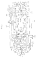
- Both the hydraulic pump unit 200 and the hydraulic motor unit 300 are variable displacement type in the present embodiment, as shown in Fig. 2.
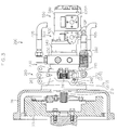
- the hydraulic pump unit 200 includes a pump shaft 210 operatively connected to the driving power source 20 by way of a flywheel 25, a pump main body 220 supported in a relatively non-rotatable manner at the pump shaft 210, and a pump case 230 for supporting the pump shaft 210 in a freely rotating manner about the axis line while accommodating the pump main body 220, as shown in Figs. 3 and 4.
- the pump case 230 is supported by the driving power source 20 by way of a flywheel housing 26 in a free state with respect to the vehicle frame 10 (see Figs. 1 and 3).
- the pump case 230A is formed with a pair of pump-side operation fluid passages 410 forming one part of the pair of operation fluid lines 400 (see Fig. 2).
- the pump case 230 is configured to form a pump space 230S for accommodating the pump main body 220 with the end wall 241 and the peripheral wall 242 of the pump case main body 240 and the pump-side port block 250 in the present embodiment.
- the pumps space 230S is preferably fluid storable.
- Fig. 6 shows a cross sectional view taken along line VI-VI in Fig. 4.
- the pair of pump-side operation fluid passages 410 is arranged substantially parallel to each other.
- a first pump-side operation fluid passage 410(F) out of the pair of pump-side operation fluid passages 410 is formed by a fluid bore perforated from a first side surface 251 of the pump-side port block 250, so that the pump-side operation fluid port 410P is positioned on the first side surface 251 of the pump-side port block 250, as shown in Fig. 6.
- the pump shaft 210 is supported in a rotatable manner about its axis line by the pump case main body 240 and the pump-side port block 250 with its first end 211 forming an input end extending outward, as shown in Figs. 4 and 5.
- the pump main body 220 includes a cylinder block 221 supported in a relatively non-rotatable manner by the pump shaft 210 so as to be positioned in the pump space 230S, and a piston unit 222 accommodated in the cylinder block 221 so as to be relatively non-rotatable but slidable in the axis line direction.
- the circular arc hole 271 is formed into a circular arc shape having the axis line of the pump-side control shaft 261 as its center.
- the regulation pin 272 is an eccentric pin having a proximal portion fixed to the pump case 230 and a distal portion engaged into the circular arc hole 271, the distal portion being eccentric with respet to the proximal portion.
- the coupling arm 285 is configured so as to integrally swing with the pump-side operation arm 265 about the pump-side control shaft 261.
- the first suction port 610P is fluidly connected to a fluid reservoir such as a fluid tank 600 by way of an appropriate external suction conduit 615.
- the suction ports of the first and second auxiliary hydraulic pump main bodies 520, 570 are fluidly connected to the fluid reservoir by way of a common suction fluid passage 630 formed in the spacer member 540, a first suction fluid passage 631 formed in the first auxiliary pump case 530, and a second suction fluid passage 632 formed in the second auxiliary pump case 580.
- the first suction fluid passage 631 has a first end opened to a contacting surface with the spacer member 540 so as to fluidly connect to the second end of the common suction fluid passage 630, a second end opened to a contacting surface with the second auxiliary hydraulic pump case 580, and an intermediate part, which is between the first and second end, fluidly connected to the suction port of the first auxiliary pump main body 520.
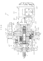
- the hydraulic motor unit 300 includes a motor main body 320 fluidly connected to the pump main body 220 by way of the pair of operation fluid lines 400, a motor shaft 310 for supporting the motor main body 320 in a relatively non-rotatable manner, and a motor case 330 for supporting the motor shaft 310 in a rotatable manner about its axis line while accommodating the motor main body 320, as shown in Figs. 2 and 8.
- the motor case 320 could be directly or indirectly supported by the supporting member such as the vehicle frame 10 independently.
- a plurality of ribs 345 are also preferably arranged on the external surface of the motor case main body 340 (see Figs. 9 and 10).
- the motor shaft 310 is supported in a rotatable manner about its axis line by the motor case 330 in a state capable of operatively driving the driving-wheels 60 (front wheel 60F and rear wheel 60R in the present embodiment).
- the motor main body 320 is supported in a relatively non-rotatable manner by the motor shaft 310 so as to be positioned in the motor space 330S, as shown in Fig. 10.
- the hydraulic motor unit 300 is of a variable displacement type, as mentioned above.
- the hydraulic motor unit 300 includes a motor-side output adjustment member 360 for changing the supply/ discharge fluid amount of the motor main body 320 according to the external operation, in addition to the above configuration.
- the motor-side output adjustment member 360 includes a motor-side operation arm 365 in addition to the above configuration.
- the motor-side operation arm 365 is coupled in a relatively non-rotatable manner to an outer end of the motor-side control shaft 361 so as to be orthogonal to the axis line of the motor-side control shaft 361.
- the regulation pin 372 is an eccentric pin having a proximal portion fixed to the motor case 330 and a distal portion engaged into the hole 371, the distal portion being eccentric with respect to the proximal portion.
- the motor shaft 380 is configured so that its second end 312 on the side opposite the first end 311 passes through the motor-side port block 350 to extend outward.
- the pair of operation fluid lines 400 includes the pair of pump-side operation fluid passages 410, the pair of motor-side operation fluid passages 415, and a pair of operation fluid conduits 405 having first ends fluidly connected to the pump-side operation fluid ports 410P and second ends fluidly connected to the motor-side operation fluid ports 415P.
- the charge line 430 is configured to replenish the operation fluid to the pair of pump-side operation fluid passages 410 in addition to the pair of motor-side operation fluid passages 415, as shown in Fig. 2.
- a pump-side check valve 455 for allowing the fluid to flow from the pump-side charge port 450P to the corresponding pump-side operation fluid passage 410 while preventing the reverse flow in each of the pump-side first charge fluid passage 452(F) and the pump-side second charge fluid passage 452(R).
- the suction amount of the motor main body 320 could be effectively prevented from becoming shorter than the discharge amount of the pump main body 220 by having the flow path resistance of a replenishing line (hereinafter referred to as motor-side charge line) for replenishing the operation fluid to the motor-side operation fluid passage 415 smaller than the flow path resistance of the replenishing line (hereinafter referred to as pump-side charge line) for replenishing the operation fluid to the pump-side operation fluid passage 410.
- motor-side charge line a replenishing line for replenishing the operation fluid to the motor-side operation fluid passage 415
- pump-side charge line the replenishing line
- the flow path resistance of the motor-side charge line could be made smaller than the flow path resistance of the pump-side charge line by having the flow path diameter of the motor-side charge line greater than the flow path diameter of the pump-side charge line.
- the second auxiliary hydraulic pump unit 550 serves as the fluid source of the charge line 430, as mentioned above.
- the HST 100 further includes a charge pressure setting line 470 for setting the hydraulic pressure of the charge line 430, as shown in Fig. 2.
- the pump-side self-suction fluid passage 481 is formed in a valve main body of the charge pressure setting relief valve 475, as shown in Fig. 4.
- the rotational force is applied to the motor shaft 310 operatively connected to the driving-wheel 60, and then the motor main body 320 intends to unintentionally perform the pump action.
- the fluid amount that flows into the pump space 230S becomes greater than the fluid amount that flows into the motor space 330S.
- the communicating line 650 includes a pump-side first port 231P formed in the pump case 230, a motor-side first port 331P formed in the motor case 330, and a communicating conduit 651 for fluidly connecting the pump-side port 231P and the motor-side first port 331P, as shown in Figs. 2, 4, 8 and 9.
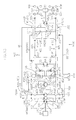
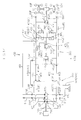
- Fig. 12 is a hydraulic circuit diagram of an HST 100B according to the present embodiment.
- the HST 100C according to the present embodiment is configured so that the flow path resistance of the motor-side charge line is less than that of the pump-side charge line by having the biasing force of the motor-side biasing member 447 less than that of the pump-side biasing member 457.
- the HST 100D omits the pump-side charge passage 450 and the pump-side check valve 455 in the HST 100 according to the embodiment 1.
- substantially only the pump-side operation fluid passages 410 are formed in the pump-side port block 250.
- the discharge line 660 is configured to fluidly connect the pump space 230S to the fluid tank 600 through a pump-side second port 232P (see Fig. 14).
Landscapes
- Engineering & Computer Science (AREA)
- General Engineering & Computer Science (AREA)
- Mechanical Engineering (AREA)
- Control Of Fluid Gearings (AREA)
- Motor Power Transmission Devices (AREA)
Applications Claiming Priority (1)
| Application Number | Priority Date | Filing Date | Title |
|---|---|---|---|
| JP2006014799A JP4775812B2 (ja) | 2006-01-24 | 2006-01-24 | Hst |
Publications (2)
| Publication Number | Publication Date |
|---|---|
| EP1811207A1 true EP1811207A1 (fr) | 2007-07-25 |
| EP1811207B1 EP1811207B1 (fr) | 2009-08-12 |
Family
ID=37799920
Family Applications (1)
| Application Number | Title | Priority Date | Filing Date |
|---|---|---|---|
| EP07101004A Not-in-force EP1811207B1 (fr) | 2006-01-24 | 2007-01-23 | Transmission hydrostatique |
Country Status (5)
| Country | Link |
|---|---|
| US (1) | US7523609B2 (fr) |
| EP (1) | EP1811207B1 (fr) |
| JP (1) | JP4775812B2 (fr) |
| CN (1) | CN101008436B (fr) |
| DE (1) | DE602007001899D1 (fr) |
Families Citing this family (5)
| Publication number | Priority date | Publication date | Assignee | Title |
|---|---|---|---|---|
| US8875507B2 (en) * | 2011-10-31 | 2014-11-04 | Deere & Company | Pump displacement control mechanism |
| JP2013164094A (ja) * | 2012-02-09 | 2013-08-22 | Kanzaki Kokyukoki Manufacturing Co Ltd | 油圧式無段変速装置 |
| WO2017065118A1 (fr) * | 2015-10-13 | 2017-04-20 | 株式会社神崎高級工機製作所 | Dispositif de transmission hydraulique |
| JP6523946B2 (ja) * | 2015-12-25 | 2019-06-05 | 株式会社クボタ | 動力伝達機構 |
| US20220307595A1 (en) * | 2019-04-26 | 2022-09-29 | Danfoss Power Solutions Ii Technology A/S | Hydraulic circuit architecture with enhanced operation efficency |
Citations (5)
| Publication number | Priority date | Publication date | Assignee | Title |
|---|---|---|---|---|
| US4494624A (en) * | 1981-05-19 | 1985-01-22 | Willy Scheuerle Fahrzeugfabrik Gmbh & Co | Hydraulic driving system with protection against overspeed |
| US5048294A (en) * | 1987-11-28 | 1991-09-17 | Hitachi Construction Machinery Co., Ltd. | Safety device for hydraulic closed circuit |
| JP2003291674A (ja) | 2002-04-03 | 2003-10-15 | Kanzaki Kokyukoki Mfg Co Ltd | ポンプユニット及び作業車 |
| FR2860560A1 (fr) * | 2003-10-03 | 2005-04-08 | Poclain Hydraulics Ind | Circuit hydraulique ouvert comprenant un dispositif de valve de delestage |
| EP1610040A1 (fr) * | 2003-03-18 | 2005-12-28 | Kobelco Cranes Co., Ltd. | Transmission hydraulique et vehicule en etant equipe |
Family Cites Families (7)
| Publication number | Priority date | Publication date | Assignee | Title |
|---|---|---|---|---|
| JPS58133645U (ja) * | 1982-03-05 | 1983-09-08 | 日立建機株式会社 | 油圧制御装置 |
| CN1006085B (zh) * | 1987-08-15 | 1989-12-13 | 石家庄煤矿机械厂 | 液控变速-调速回路 |
| JP3508955B2 (ja) * | 1995-03-24 | 2004-03-22 | 株式会社小松製作所 | 油圧モータの駆動装置 |
| DE19612873A1 (de) * | 1996-03-30 | 1997-10-02 | Zahnradfabrik Friedrichshafen | Hydrostatisch-mechanisches Getriebe zum Antrieb einer Mischtrommel |
| JP2001150969A (ja) * | 1999-11-29 | 2001-06-05 | Hatsuta Kakusanki Kk | 管理作業車 |
| FI107075B (fi) * | 2000-02-28 | 2001-05-31 | Ideachip Oy Insinoeoeritoimist | Hydraulimoottorin vuotoöljyn palautuslaite |
| JP3920070B2 (ja) * | 2001-10-12 | 2007-05-30 | 株式会社 神崎高級工機製作所 | 車輌 |
-
2006
- 2006-01-24 JP JP2006014799A patent/JP4775812B2/ja not_active Expired - Fee Related
-
2007
- 2007-01-23 DE DE602007001899T patent/DE602007001899D1/de active Active
- 2007-01-23 EP EP07101004A patent/EP1811207B1/fr not_active Not-in-force
- 2007-01-24 CN CN2007100043524A patent/CN101008436B/zh not_active Expired - Fee Related
- 2007-01-24 US US11/626,783 patent/US7523609B2/en not_active Expired - Fee Related
Patent Citations (5)
| Publication number | Priority date | Publication date | Assignee | Title |
|---|---|---|---|---|
| US4494624A (en) * | 1981-05-19 | 1985-01-22 | Willy Scheuerle Fahrzeugfabrik Gmbh & Co | Hydraulic driving system with protection against overspeed |
| US5048294A (en) * | 1987-11-28 | 1991-09-17 | Hitachi Construction Machinery Co., Ltd. | Safety device for hydraulic closed circuit |
| JP2003291674A (ja) | 2002-04-03 | 2003-10-15 | Kanzaki Kokyukoki Mfg Co Ltd | ポンプユニット及び作業車 |
| EP1610040A1 (fr) * | 2003-03-18 | 2005-12-28 | Kobelco Cranes Co., Ltd. | Transmission hydraulique et vehicule en etant equipe |
| FR2860560A1 (fr) * | 2003-10-03 | 2005-04-08 | Poclain Hydraulics Ind | Circuit hydraulique ouvert comprenant un dispositif de valve de delestage |
Also Published As
| Publication number | Publication date |
|---|---|
| EP1811207B1 (fr) | 2009-08-12 |
| US7523609B2 (en) | 2009-04-28 |
| JP2007198419A (ja) | 2007-08-09 |
| DE602007001899D1 (de) | 2009-09-24 |
| CN101008436A (zh) | 2007-08-01 |
| CN101008436B (zh) | 2010-06-16 |
| US20070169475A1 (en) | 2007-07-26 |
| JP4775812B2 (ja) | 2011-09-21 |
Similar Documents
| Publication | Publication Date | Title |
|---|---|---|
| US7775309B2 (en) | Pump unit | |
| US7374010B2 (en) | Transmission for a working vehicle and vehicle | |
| US20070209355A1 (en) | Pump Unit and Hydrostatic Transmission | |
| US7409827B2 (en) | Working vehicle | |
| US20090178400A1 (en) | Neutral Valve Structure | |
| EP1811207B1 (fr) | Transmission hydrostatique | |
| US20080099269A1 (en) | Wheel Motor Device | |
| US20080053736A1 (en) | Wheel Motor Device, Working Vehicle, and Hydraulic Drive Working Vehicle | |
| EP2735737A1 (fr) | Dispositif de piston axial à cylindrée variable | |
| US20080185053A1 (en) | Pump system, charge relief mechanism and oil pressure control mechanism | |
| US9416859B2 (en) | Hydrostatic stepless transmission | |
| US7334404B2 (en) | Pump unit | |
| US7162871B2 (en) | Pump unit | |
| JP4568805B2 (ja) | 車輌におけるpto装置 | |
| JP4617427B2 (ja) | ポンプ装置 | |
| JP2004011847A (ja) | 静油圧式無段変速装置の油圧回路 | |
| JP2007309288A (ja) | デュアルポンプユニット |
Legal Events
| Date | Code | Title | Description |
|---|---|---|---|
| PUAI | Public reference made under article 153(3) epc to a published international application that has entered the european phase |
Free format text: ORIGINAL CODE: 0009012 |
|
| AK | Designated contracting states |
Kind code of ref document: A1 Designated state(s): AT BE BG CH CY CZ DE DK EE ES FI FR GB GR HU IE IS IT LI LT LU LV MC NL PL PT RO SE SI SK TR |
|
| AX | Request for extension of the european patent |
Extension state: AL BA HR MK YU |
|
| 17P | Request for examination filed |
Effective date: 20071004 |
|
| 17Q | First examination report despatched |
Effective date: 20071106 |
|
| AKX | Designation fees paid |
Designated state(s): DE FR IT |
|
| GRAP | Despatch of communication of intention to grant a patent |
Free format text: ORIGINAL CODE: EPIDOSNIGR1 |
|
| GRAS | Grant fee paid |
Free format text: ORIGINAL CODE: EPIDOSNIGR3 |
|
| GRAA | (expected) grant |
Free format text: ORIGINAL CODE: 0009210 |
|
| AK | Designated contracting states |
Kind code of ref document: B1 Designated state(s): DE FR IT |
|
| REF | Corresponds to: |
Ref document number: 602007001899 Country of ref document: DE Date of ref document: 20090924 Kind code of ref document: P |
|
| PLBE | No opposition filed within time limit |
Free format text: ORIGINAL CODE: 0009261 |
|
| STAA | Information on the status of an ep patent application or granted ep patent |
Free format text: STATUS: NO OPPOSITION FILED WITHIN TIME LIMIT |
|
| 26N | No opposition filed |
Effective date: 20100517 |
|
| PGRI | Patent reinstated in contracting state [announced from national office to epo] |
Ref country code: IT Effective date: 20110501 |
|
| PGFP | Annual fee paid to national office [announced via postgrant information from national office to epo] |
Ref country code: FR Payment date: 20120206 Year of fee payment: 6 |
|
| PGFP | Annual fee paid to national office [announced via postgrant information from national office to epo] |
Ref country code: IT Payment date: 20120123 Year of fee payment: 6 |
|
| PGFP | Annual fee paid to national office [announced via postgrant information from national office to epo] |
Ref country code: DE Payment date: 20130131 Year of fee payment: 7 |
|
| REG | Reference to a national code |
Ref country code: FR Ref legal event code: ST Effective date: 20130930 |
|
| PG25 | Lapsed in a contracting state [announced via postgrant information from national office to epo] |
Ref country code: FR Free format text: LAPSE BECAUSE OF NON-PAYMENT OF DUE FEES Effective date: 20130131 |
|
| PG25 | Lapsed in a contracting state [announced via postgrant information from national office to epo] |
Ref country code: IT Free format text: LAPSE BECAUSE OF NON-PAYMENT OF DUE FEES Effective date: 20130123 |
|
| REG | Reference to a national code |
Ref country code: DE Ref legal event code: R119 Ref document number: 602007001899 Country of ref document: DE |
|
| REG | Reference to a national code |
Ref country code: DE Ref legal event code: R119 Ref document number: 602007001899 Country of ref document: DE Effective date: 20140801 |
|
| PG25 | Lapsed in a contracting state [announced via postgrant information from national office to epo] |
Ref country code: DE Free format text: LAPSE BECAUSE OF NON-PAYMENT OF DUE FEES Effective date: 20140801 |