EP1811232A2 - Porte d'un appareil ménager - Google Patents
Porte d'un appareil ménager Download PDFInfo
- Publication number
- EP1811232A2 EP1811232A2 EP20060126649 EP06126649A EP1811232A2 EP 1811232 A2 EP1811232 A2 EP 1811232A2 EP 20060126649 EP20060126649 EP 20060126649 EP 06126649 A EP06126649 A EP 06126649A EP 1811232 A2 EP1811232 A2 EP 1811232A2
- Authority
- EP
- European Patent Office
- Prior art keywords
- door
- domestic appliance
- appliance door
- condensed water
- door device
- Prior art date
- Legal status (The legal status is an assumption and is not a legal conclusion. Google has not performed a legal analysis and makes no representation as to the accuracy of the status listed.)
- Withdrawn
Links
- XLYOFNOQVPJJNP-UHFFFAOYSA-N water Substances O XLYOFNOQVPJJNP-UHFFFAOYSA-N 0.000 claims description 28
- 239000011521 glass Substances 0.000 claims description 27
- 238000007599 discharging Methods 0.000 claims description 6
- 238000010411 cooking Methods 0.000 description 11
- 239000000463 material Substances 0.000 description 5
- 230000015572 biosynthetic process Effects 0.000 description 3
- 230000005494 condensation Effects 0.000 description 3
- 238000009833 condensation Methods 0.000 description 3
- 238000005755 formation reaction Methods 0.000 description 3
- 230000010354 integration Effects 0.000 description 2
- 230000009191 jumping Effects 0.000 description 2
- 238000004519 manufacturing process Methods 0.000 description 2
- 208000027418 Wounds and injury Diseases 0.000 description 1
- 239000000853 adhesive Substances 0.000 description 1
- 230000001070 adhesive effect Effects 0.000 description 1
- 239000003795 chemical substances by application Substances 0.000 description 1
- 238000010276 construction Methods 0.000 description 1
- 230000006378 damage Effects 0.000 description 1
- 230000001419 dependent effect Effects 0.000 description 1
- 238000005516 engineering process Methods 0.000 description 1
- 208000014674 injury Diseases 0.000 description 1
- 238000012986 modification Methods 0.000 description 1
- 230000004048 modification Effects 0.000 description 1
Images


Classifications
-
- F—MECHANICAL ENGINEERING; LIGHTING; HEATING; WEAPONS; BLASTING
- F24—HEATING; RANGES; VENTILATING
- F24C—DOMESTIC STOVES OR RANGES ; DETAILS OF DOMESTIC STOVES OR RANGES, OF GENERAL APPLICATION
- F24C15/00—Details
- F24C15/02—Doors specially adapted for stoves or ranges
- F24C15/04—Doors specially adapted for stoves or ranges with transparent panels
- F24C15/045—Doors specially adapted for stoves or ranges with transparent panels being dismountable, e.g. giving access for cleaning
Definitions
- the invention relates to a domestic appliance door device according to the preamble of claim 1.
- cooking appliance door devices which comprise a door pane and a multi-part carrier device for supporting the door pane.
- the door glass is always glued to the support device.
- one-piece, frame-shaped carrier devices are known, with which the door glass is glued.
- the object of the invention is in particular to provide a generic household appliance door device that is particularly cost-effective and easy to service. Another object of the invention is to dissipate condensed water from a door pane of a generic domestic appliance door device via a carrier device in a defined manner.
- the invention is based on a domestic appliance door device, in particular a cooking appliance door device, with a door pane and a multi-part carrier device for supporting the door pane.
- the door pane between at least two support elements of the door glass is frictionally clamped by a perpendicular to the extension plane of the door glass clamping force component.
- a montage and service-friendly, detachable connection between the door glass and the support device can be created.
- a lifetime can be due to the largely excluded material fatigue compared to domestic appliance door devices with glued door panels be greatly increased.
- advantages can be achieved with regard to the removal of condensed water, which will be explained in more detail below.
- support elements in this context, in particular those components are to be referred to, which extend at least over a substantial proportion, for example over more than 80%, the length of a side edge of the door glass.
- the domestic appliance door device according to the invention is particularly advantageous in connection with cooking appliances used, but also in other areas, such as transparent refrigerator doors, is conceivable.
- the domestic appliance door device comprises at least one screw for producing the clamping force for holding the door pane
- the clamping force can be well dosed and the clamping connection can be easily released by loosening the screw.
- Embodiments of the invention with a plurality of symmetrically arranged screws are particularly advantageous, since thereby jumping of the door pane due to material stresses can be avoided.
- an effective clamping force component running perpendicular to the plane of extension can be produced.
- the carrier device comprises a central carrier element which jams the door pane at its lower edge. This allows a particularly secure hold can be achieved and slipping out of the door glass can be avoided even with loosened screws or with loose clamp connection.
- a particularly cost-effective production of the carrier device from profile elements can be achieved if the carrier device comprises a multi-part carrier frame, on which the central carrier element presses the door pane.
- the domestic appliance door device comprises at least one screw connection for simultaneously securing the central support element and a hinge element to a support frame of the support device.
- the central carrier element comprises at least one condensed water guide means for the controlled discharge of condensed water.
- condensed water guide means for the controlled discharge of condensed water.
- any condensation agent that directs a flow of condensed water should be referred to as condensate-carrying means.
- the condensed water guide means comprises two symmetrical guide grooves which converge obliquely towards the center of the central support element.
- Controlled discharge of condensed water from the home appliance door can be achieved if the condensed water guide means comprises a central drip opening for discharging the condensed water into a gutter.
- the gutter can be arranged, for example, on a body of a domestic appliance comprising the domestic appliance door device.
- At least one carrier element of the carrier device comprises a rear engagement element which is intended to encompass an edge of the door pane
- the frictional connection can be supplemented by a form fit, and can take place in the region of the edge of the door pane be dispensed with a separate contact element for supporting the jammed door glass.
- a manufacturing technology simple and at the same time efficient design can be achieved if the rear engagement element is designed channel-shaped.
- the door glass can then be supported vertically in the gutter, for example when the appliance door is closed, and at the same time guided horizontally in the gutter.
- rear engagement member is provided for discharging condensed water into the condensed water guide means, further functional integration can be achieved, and effective drainage of condensed water from both sides of the door glass can be ensured.
- Lever forces acting on a clamping connection can be avoided if the door pane is frictionally clamped on two opposite edges between in each case two carrier elements.
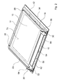
- FIG. 1 shows a domestic appliance door device, namely a cooking appliance door, with a door pane 10, namely an inner pane, and a multi-part carrier device 12 for supporting the door pane 10.
- the door glass 10 is frictionally clamped between an upper support element 14, a central support element 16 arranged at the lower edge of the door pane 10 and further support elements 18, 20 of the door pane 10.
- the support members 14-20 are sandwiched on both sides at opposite edges of the door glass 10.
- the upper support member 14 and the lower, central support member 16 abut an inner side 74 of the door glass 10.
- the inner side 74 faces a cooking chamber of the cooking appliance door comprising the cooking appliance door when the cooking appliance door is closed.
- the further carrier elements 18, 20 rest on a side surface 70 of the door pane 10 opposite the inner side 74 (FIG. 3).
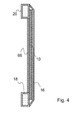
- the sandwich-like construction of the cooking appliance door is shown very schematically in FIG.
- the further carrier elements 18, 20 are formed as angle profiles and, together with the upper carrier element 14 and the central carrier element 16, form a rectangular carrier frame 26 of a domestic appliance door 36 which comprises the domestic appliance door device.
- the household appliance door 36 is part of a cooking appliance, not explicitly shown here, namely a household oven, and can be used universally for different series of household baking oven.
- the household appliance door 36 also comprises a front pane (not explicitly shown here) and, depending on the series, may also comprise an intermediate pane.
- the appliance door device comprises four screws 28-34, by which the upper support element 14 and the central support element 16 are connected to the support frame 26.
- the rectangular door panel 10 each have a recess 38-40, which is penetrated by one of the screws 28-34 and is covered by one of the support elements 14, 16.
- Two symmetrical, bead-like formations 46, 48 at the lower edge of the central support member 16 allow lateral guidance of the door panel 10.
- the central support member 16 clamps the door panel 10 at its lower edge by pressing the door panel 10 to the multi-part support frame 26 of the support device 12.
- the central support member 16 further covers with a clamping portion 72, in which the sheet material of the support member 16 is folded, from the lower edge of an inner side 74 of the door panel 10, which faces a cooking chamber of the household appliance door 36 household baking oven ( Figure 3).
- FIG. 2 shows two lateral screw connections 50, 52 for simultaneously securing the central carrier element 16 and a hinge element 54, 56 to the carrier frame 26 or to the other, vertical carrier elements 18, 20 of the carrier device 12.
- the lower edge of the central support member 16 is channel-shaped and has in profile ( Figure 3) on a collecting tab 76 which projects at an angle of about 10 ° in the direction of the interior of the household appliance door 36.
- the lower edge of the central support member 16 forms a condensed water guide 58 for the controlled discharge of condensed water.
- the condensed water guide means 58 comprises two symmetrical guide grooves 60, 62 which converge obliquely towards the center of the central support element 16 and open into a central drip opening 64 for discharging the condensed water into a gutter or profiled rail of the domestic appliance, not explicitly shown here, in which the condensed water evaporates can.
- the drip opening 64 in particular forms a defined spoiler lip for draining the condensate water into the profile rail.
- the central carrier element 16 of the carrier device 12 comprises a rear engagement element 66 (FIG. 3), which is intended to encompass an edge of the door pane 10.
- the Schugreifungselement 66 is channel-shaped and surmounted with a protruding catch tab 68 a the interior of the appliance door 36 facing side surface 70 of the door glass 10 so that dripping from the side surface 70 condensate is trapped securely in the catch tab 68 and the rear engagement element 66.
- the channel shape of the rear engagement element 66 is realized in that a position of the sheet material in a continuation of the clamping portion 72 is U-shaped bent, so that the rear engagement element 66 and the clamping portion 72 together a hook-shaped, in the direction of the interior of the household appliance door 36 open area of the profile of the central support element 16 form.
- the Hintergreifungselement 66 opens laterally into the condensed water guide means 58 and is therefore provided for discharging condensation into the condensed water guide means 58.
Landscapes
- Engineering & Computer Science (AREA)
- Chemical & Material Sciences (AREA)
- Combustion & Propulsion (AREA)
- Mechanical Engineering (AREA)
- General Engineering & Computer Science (AREA)
- Securing Of Glass Panes Or The Like (AREA)
- Electric Ovens (AREA)
Applications Claiming Priority (1)
| Application Number | Priority Date | Filing Date | Title |
|---|---|---|---|
| DE200610002915 DE102006002915A1 (de) | 2006-01-20 | 2006-01-20 | Hausgerätetürvorrichtung |
Publications (1)
| Publication Number | Publication Date |
|---|---|
| EP1811232A2 true EP1811232A2 (fr) | 2007-07-25 |
Family
ID=38006868
Family Applications (1)
| Application Number | Title | Priority Date | Filing Date |
|---|---|---|---|
| EP20060126649 Withdrawn EP1811232A2 (fr) | 2006-01-20 | 2006-12-20 | Porte d'un appareil ménager |
Country Status (2)
| Country | Link |
|---|---|
| EP (1) | EP1811232A2 (fr) |
| DE (1) | DE102006002915A1 (fr) |
Cited By (3)
| Publication number | Priority date | Publication date | Assignee | Title |
|---|---|---|---|---|
| CN101890177A (zh) * | 2009-05-19 | 2010-11-24 | 博西华电器(江苏)有限公司 | 具有正面框架的家用电器 |
| ITRN20100013A1 (it) * | 2010-04-02 | 2011-10-03 | Indesit Co Spa | Forno di cottura. |
| WO2019091791A1 (fr) * | 2017-11-13 | 2019-05-16 | BSH Hausgeräte GmbH | Appareil de cuisson électroménager comprenant un compartiment de cuisson |
Family Cites Families (5)
| Publication number | Priority date | Publication date | Assignee | Title |
|---|---|---|---|---|
| DE2205279B2 (de) * | 1972-02-04 | 1978-11-09 | Bosch-Siemens Hausgeraete Gmbh, 7000 Stuttgart | Backofen-Turf enster |
| US4041930A (en) * | 1975-11-28 | 1977-08-16 | Mills Products, Inc. | Window unit for oven doors |
| GB2290611B (en) * | 1994-06-14 | 1998-06-24 | Blue Circle Domestic Appliance | Cooking appliances |
| DE10219349B4 (de) * | 2002-04-30 | 2004-12-30 | BSH Bosch und Siemens Hausgeräte GmbH | Tür für ein Gerät, insbesondere für einen Garofen |
| DE10336138B3 (de) * | 2003-08-04 | 2004-10-14 | Miele & Cie. Kg | Tür für ein Haushaltsgerät mit demontierbarer Scheibe |
-
2006
- 2006-01-20 DE DE200610002915 patent/DE102006002915A1/de not_active Withdrawn
- 2006-12-20 EP EP20060126649 patent/EP1811232A2/fr not_active Withdrawn
Cited By (5)
| Publication number | Priority date | Publication date | Assignee | Title |
|---|---|---|---|---|
| CN101890177A (zh) * | 2009-05-19 | 2010-11-24 | 博西华电器(江苏)有限公司 | 具有正面框架的家用电器 |
| CN101890177B (zh) * | 2009-05-19 | 2015-09-30 | 博西华电器(江苏)有限公司 | 具有正面框架的消毒器 |
| ITRN20100013A1 (it) * | 2010-04-02 | 2011-10-03 | Indesit Co Spa | Forno di cottura. |
| WO2011121506A1 (fr) * | 2010-04-02 | 2011-10-06 | Indesit Company S.P.A. | Four de cuisson |
| WO2019091791A1 (fr) * | 2017-11-13 | 2019-05-16 | BSH Hausgeräte GmbH | Appareil de cuisson électroménager comprenant un compartiment de cuisson |
Also Published As
| Publication number | Publication date |
|---|---|
| DE102006002915A1 (de) | 2007-07-26 |
Similar Documents
| Publication | Publication Date | Title |
|---|---|---|
| DE102009025038B4 (de) | Kochdunst-Eintrittsvorrichtung mit abnehmbarer deckelförmiger Verschließeinrichtung | |
| EP2264387A2 (fr) | Appareil de réfrigération et/ou de refroidissement | |
| DE102009044383A1 (de) | Morphologisches Modulsystem zur Erstellung von unterschiedlichen Gebäudeverschlüssen | |
| EP2553343B1 (fr) | Porte de four et procédé pour fixer un habillage de porte à une telle porte de four | |
| DE102004002466A1 (de) | Haushaltsgerätetür mit einer Vorrichtung mit einer Scharniereinheit | |
| DE102004049595B3 (de) | Dachhaken | |
| EP2679929A1 (fr) | Système de montage et d'étanchéité pour l'intégration d'une multitude de modules en forme de plaques dans un toit incliné | |
| DE10037881C2 (de) | Tür für ein Haushaltsgerät, insbesondere einen Haushaltsgarofen | |
| EP1811232A2 (fr) | Porte d'un appareil ménager | |
| DE19718714C2 (de) | Isolierelement aus zwei oder mehreren, aus Glas oder Kunststoff gefertigten Scheiben | |
| EP3121360B1 (fr) | Système de fixation pour éléments de recouvrement | |
| EP2366856B1 (fr) | Agencement de porte coulissante dotée d'un obturateur et procédé d'agencement d'un obturateur | |
| EP2267263B1 (fr) | Joint d'étanchéité pour porte | |
| DE19855028B4 (de) | Dachfensterkonstruktionen | |
| DE19758464C2 (de) | Isolierelement aus wenigstens zwei Glas- oder Kunststoffscheiben und mit Profilschienen oder -teilen zur Montage in einem Rahmen | |
| EP1918645B1 (fr) | Porte d'un four de cuisson | |
| EP1308676A2 (fr) | Porte d'un four de cuisson | |
| EP0790469A2 (fr) | Cuisinière avec un joint d'étanchéité élastique | |
| EP1277910B1 (fr) | Joint descendant pour une porte sans seuil | |
| DE20109557U1 (de) | Innenscharnier insbesondere in einem Schaltgehäuse | |
| DE102007021559A1 (de) | Haushalts-Kältegerät | |
| DE10136348C1 (de) | Halterung für eine ausrichtbare Befestigung der Stützen eines Balkongeländers | |
| DE2540027C3 (de) | Haube zur spritzwasserdichten Belüftung von Innenräumen von Fahrzeugen o.dgl | |
| EP1479978B1 (fr) | Support de panneaux | |
| EP1688577B1 (fr) | Languette de raccord pour fixer des cadres de fenêtre ou porte à un cadre de base ou à un mur |
Legal Events
| Date | Code | Title | Description |
|---|---|---|---|
| PUAI | Public reference made under article 153(3) epc to a published international application that has entered the european phase |
Free format text: ORIGINAL CODE: 0009012 |
|
| AK | Designated contracting states |
Kind code of ref document: A2 Designated state(s): AT BE BG CH CY CZ DE DK EE ES FI FR GB GR HU IE IS IT LI LT LU LV MC NL PL PT RO SE SI SK TR |
|
| AX | Request for extension of the european patent |
Extension state: AL BA HR MK YU |
|
| STAA | Information on the status of an ep patent application or granted ep patent |
Free format text: STATUS: THE APPLICATION IS DEEMED TO BE WITHDRAWN |
|
| 18D | Application deemed to be withdrawn |
Effective date: 20140701 |