EP1811264A1 - Procédé et dispositif destinés à la détection de structures de surface dentaires - Google Patents
Procédé et dispositif destinés à la détection de structures de surface dentaires Download PDFInfo
- Publication number
- EP1811264A1 EP1811264A1 EP07100704A EP07100704A EP1811264A1 EP 1811264 A1 EP1811264 A1 EP 1811264A1 EP 07100704 A EP07100704 A EP 07100704A EP 07100704 A EP07100704 A EP 07100704A EP 1811264 A1 EP1811264 A1 EP 1811264A1
- Authority
- EP
- European Patent Office
- Prior art keywords
- detector element
- vibrations
- tooth
- evaluated
- detected
- Prior art date
- Legal status (The legal status is an assumption and is not a legal conclusion. Google has not performed a legal analysis and makes no representation as to the accuracy of the status listed.)
- Granted
Links
- 238000000034 method Methods 0.000 title claims abstract description 16
- 238000011156 evaluation Methods 0.000 claims abstract description 24
- 230000010355 oscillation Effects 0.000 claims abstract description 14
- 238000001514 detection method Methods 0.000 claims abstract description 6
- 230000001419 dependent effect Effects 0.000 claims abstract description 4
- 239000000126 substance Substances 0.000 claims abstract description 3
- 230000005284 excitation Effects 0.000 claims description 33
- 230000033001 locomotion Effects 0.000 claims description 9
- 230000003993 interaction Effects 0.000 claims description 2
- 239000000919 ceramic Substances 0.000 abstract description 2
- 230000000638 stimulation Effects 0.000 abstract 2
- 239000000463 material Substances 0.000 description 6
- 238000010408 sweeping Methods 0.000 description 5
- 230000007274 generation of a signal involved in cell-cell signaling Effects 0.000 description 2
- 238000010422 painting Methods 0.000 description 2
- 235000019592 roughness Nutrition 0.000 description 2
- 238000000926 separation method Methods 0.000 description 2
- 238000002679 ablation Methods 0.000 description 1
- 230000005540 biological transmission Effects 0.000 description 1
- 230000000694 effects Effects 0.000 description 1
- 238000012854 evaluation process Methods 0.000 description 1
- 230000001788 irregular Effects 0.000 description 1
- 238000003754 machining Methods 0.000 description 1
- 238000004519 manufacturing process Methods 0.000 description 1
- 238000005259 measurement Methods 0.000 description 1
- 238000000691 measurement method Methods 0.000 description 1
- 230000002123 temporal effect Effects 0.000 description 1
- 238000002604 ultrasonography Methods 0.000 description 1
Images
Classifications
-
- A—HUMAN NECESSITIES
- A61—MEDICAL OR VETERINARY SCIENCE; HYGIENE
- A61C—DENTISTRY; APPARATUS OR METHODS FOR ORAL OR DENTAL HYGIENE
- A61C19/00—Dental auxiliary appliances
- A61C19/04—Measuring instruments specially adapted for dentistry
-
- G—PHYSICS
- G01—MEASURING; TESTING
- G01B—MEASURING LENGTH, THICKNESS OR SIMILAR LINEAR DIMENSIONS; MEASURING ANGLES; MEASURING AREAS; MEASURING IRREGULARITIES OF SURFACES OR CONTOURS
- G01B7/00—Measuring arrangements characterised by the use of electric or magnetic techniques
- G01B7/34—Measuring arrangements characterised by the use of electric or magnetic techniques for measuring roughness or irregularity of surfaces
-
- G—PHYSICS
- G01—MEASURING; TESTING
- G01N—INVESTIGATING OR ANALYSING MATERIALS BY DETERMINING THEIR CHEMICAL OR PHYSICAL PROPERTIES
- G01N29/00—Investigating or analysing materials by the use of ultrasonic, sonic or infrasonic waves; Visualisation of the interior of objects by transmitting ultrasonic or sonic waves through the object
- G01N29/04—Analysing solids
- G01N29/045—Analysing solids by imparting shocks to the workpiece and detecting the vibrations or the acoustic waves caused by the shocks
-
- G—PHYSICS
- G01—MEASURING; TESTING
- G01N—INVESTIGATING OR ANALYSING MATERIALS BY DETERMINING THEIR CHEMICAL OR PHYSICAL PROPERTIES
- G01N29/00—Investigating or analysing materials by the use of ultrasonic, sonic or infrasonic waves; Visualisation of the interior of objects by transmitting ultrasonic or sonic waves through the object
- G01N29/04—Analysing solids
- G01N29/12—Analysing solids by measuring frequency or resonance of acoustic waves
-
- G—PHYSICS
- G01—MEASURING; TESTING
- G01N—INVESTIGATING OR ANALYSING MATERIALS BY DETERMINING THEIR CHEMICAL OR PHYSICAL PROPERTIES
- G01N2291/00—Indexing codes associated with group G01N29/00
- G01N2291/02—Indexing codes associated with the analysed material
- G01N2291/024—Mixtures
- G01N2291/02483—Other human or animal parts, e.g. bones
Definitions
- the invention relates to a method and a device for detecting surface structures, in which a detector element is brought into contact with the dental surface to be detected and in which a sensor element for detecting vibrations is connected to the detector element.
- the disadvantage is that an excitation is necessary. This leads to increased costs and it has been shown that the scattering of the exciting system affect the vibration behavior of the detector element in such a way that corrective measures are required in the evaluation. In addition, a high voltage signal is used to generate the oscillation pulse. This can lead to difficulties in the evaluation process.
- the detector element is brought into contact with the surface of the tooth to be detected, wherein a sensor element for detecting the surface structure of the tooth dependent vibrations is connected to the detector element, then detects the vibrations of the detector element and evaluated in that the detector element is moved with or without device-side excitation over the surface of the tooth to be detected, and the resulting oscillations of the detector element are detected and the vibrations not caused by the device-side excitation are evaluated.
- vibrations are understood to mean vibrations that are excited by the surface of the tooth itself. These vibrations can also be modulated on a device-side excitation.
- the oscillations of the detector element caused by device-side excitation are additionally evaluated. This allows a comparison of the two results obtained from the different types of excitation and thus contributes to a more extensive analysis.
- the oscillations of the detector element are evaluated in a device-side excitation-free time range.
- the vibrations are caused only by the swept surface.
- the device-induced oscillations in the signal to be evaluated of the detector element at least 10 times the amplitude of the amplitude of the vibrations not caused by the device-side excitation. This is a for the evaluation clear separation of the two areas possible.
- the device-side excitations have an amplitude on the order of 2 V and the signal caused by the surface has an amplitude of the order of 2 mV.
- the signal obtained from the excitation is evaluated in the time domain and / or in the frequency domain.
- a piezoceramic or magnetostrictive oscillator is used as the sensor element and / or sensors such as vibration transducers or strain gauges to generate evaluable signals.
- the method is particularly suitable for the detection of surface structures of tooth substance.
- the device according to the invention for detecting dental surface structures comprises a detector element which can perform vibrations, furthermore a sensor element for detecting the vibrations of the detector element in interaction with a surface of the tooth to be detected and an evaluation unit connected to the sensor element for evaluating the vibrations of the detector element obtained signals.
- the sensor element is designed so that the vibrations that are caused when moving the non-device side excited detector element over the surface, can be evaluated.
- the proposed method and the associated device make use of the fact that, when passing over a surface with a detector element, for example with the distal end of a tool tip of a piezo or magnetostrictively driven ultrasonic scaler, a signal is generated, eg due to the vibrations during movement in a sensor element the reciprocal piezoelectric effect. With the aid of this signal, it can be decided whether the detector element is located on a surface and different surfaces can be distinguished from one another if an appropriate detection was carried out in an evaluation device.
- Suitable material properties include, among others, the modulus of elasticity, the material hardness and the speed of sound in the material.
- the oscillations of the detector element resulting from the movement of the detector element over the surface of the tooth to be detected are evaluated in a time range with device-side excitation. This is possible by the order of magnitude separation of the signal levels originating from the different excitations and prevents difficulties due to interruptions in various measurement methods.
- the movement of the detector element over the surface of the tooth to be detected arising oscillations of the detector element and the vibrations caused by device-side excitation evaluated simultaneously. This allows the direct simultaneous comparison of the results of both evaluations.
- the signal can be examined either in the time domain or in the frequency domain by means of suitable evaluation algorithms.
- piezoelectric or magnetostrictive sensor elements can be provided as the drive of an ultrasound scaler.
- sensor elements such as vibration transducers or strain gauges can also be used.
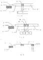
- FIG. 1A shows a hand instrument 1 in the form of an ultrasonic caliper as an example of a device for detecting surface structures.
- This dental hand instrument 1 comprises a working tip 2, which is set in vibration by means of a piezoceramic 3.
- a counterweight 4 is provided in the hand instrument.
- Such ultrasonic scaler are known from the prior art.
- material can be removed from a tooth 5 from the upper side 6.
- the working tip 2 can also be used as a detector element.
- the piezoceramic 3 serves as a sensor element for detecting the vibrations of the detector element when it is moved over the surface 6 of the tooth 5 without being stimulated additionally.
- This is a painting, a material removal is not intended in this operating condition.
- the signal obtained by the sweeping can be used after a corresponding evaluation for power control of the oscillator and thus for ablation.
- the piezoceramic 3 as a sensor element is connected to an evaluation unit 7, in which the signal generated by the sensor element is evaluated either in the time domain and / or in the frequency domain.
- the signal generated by the sensor element is evaluated either in the time domain and / or in the frequency domain.
- the amplitude, the frequency, the envelope or the power density of the signal obtained can be evaluated.
- the stress level on a rough surface is significantly higher than on a smooth surface.
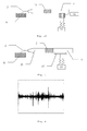
- the signal may have the form of FIG. 4 by way of example.
- the evaluation unit 7 is designed such that vibrations of the detector element 2, which when sweeping the to be recognized Surface structure of the tooth 5 occur, can be evaluated based on signal generated in the sensor element 3, without the detector element 2 is excited by the hand instrument, ie, that the vibrations are used due to the movement of the detector element on the surface 6 along for signal generation.
- the piezoceramic can be divided into a drive part 3a and a sensor part 3b, shown in FIG. 1B .
- another connection 8 ' is required.
- the actual sensor element 7b is partially electrically separated from the actuator element 7b, so that a simplified evaluation can be used, since the high-voltage part of the drive is separated from the measurement.
- a sensor element in the form of a vibration sensor 12, which is connected to an evaluation unit 13, is provided on the dental hand instrument 11.
- the detector element 2 is set in motion during its movement via the tooth 5, which are transmitted via the piezoceramic 3 and the counterweight 4 to the vibration sensor 12 and there cause a signal which is evaluated in the evaluation unit 13.
- the vibration sensor 12 is connected downstream of the piezoceramic 3 as a drive of the detector element designed as a working tip 2 in the case of a machining of the tooth 5, wherein the vibration sensor 12 and the counterweight 4 is connected downstream.
- the vibration sensor is advantageously mounted in the longitudinal direction of the handpiece, but may also be perpendicular thereto ( FIG. 2B ).
- the dental hand instrument 21 comprises a piezoceramic 3 as a drive for a working tip 2, which can also be used as a detector element, wherein the vibrations caused by the sweep of the detector element 2 via the tooth 5 are detected in a sensor element 22 designed as a strain gauge and in an evaluation unit 23 be evaluated.
- the strain gauge advantageously extends over the counterweight of the handpiece, but can also be attached to any other locations.
- an attachment takes place at the points at which a deflection takes place and, for example, not over the region of the piezoceramics, since there is a vibration node at these points.
- the signals from the piezoceramic are not detected, but rather the oscillations are detected and evaluated by additional sensor elements.
- FIG. 4 shows the course of a signal obtained from the sensor element when passing over a surface. It shows the voltage curve over time.
- the shape of the voltage excitations can be used to draw conclusions about the swept surface.
- the painting of the Surface generates an irregular voltage curve, which leads to larger voltage amplitudes with a larger roughness of the surface.
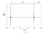
- FIG. 5 shows a signal in the form of a temporal voltage profile which results from the simultaneous sweeping over of a surface and a regular short-term device-side excitation of the surface.
- the device-side excitation of the surface leads to voltage spikes in the voltage curve, the amplitudes of which are substantially greater in comparison to the amplitudes which are produced by sweeping the surface without device-side excitation, usually more than a factor of 10.
- the time intervals of the device-side excitations are 65 ms, so that at a typical speed of about 3 cm / s, with which the detector element 2 is guided over the surface, an excitation of the surface takes place about every 0.2 cm.
Landscapes
- Health & Medical Sciences (AREA)
- Physics & Mathematics (AREA)
- Life Sciences & Earth Sciences (AREA)
- General Health & Medical Sciences (AREA)
- General Physics & Mathematics (AREA)
- Pathology (AREA)
- Immunology (AREA)
- Biochemistry (AREA)
- Analytical Chemistry (AREA)
- Chemical & Material Sciences (AREA)
- Acoustics & Sound (AREA)
- Oral & Maxillofacial Surgery (AREA)
- Veterinary Medicine (AREA)
- Public Health (AREA)
- Animal Behavior & Ethology (AREA)
- Epidemiology (AREA)
- Dentistry (AREA)
- Biophysics (AREA)
- Biomedical Technology (AREA)
- Engineering & Computer Science (AREA)
- Dental Tools And Instruments Or Auxiliary Dental Instruments (AREA)
Applications Claiming Priority (1)
| Application Number | Priority Date | Filing Date | Title |
|---|---|---|---|
| DE102006002616A DE102006002616A1 (de) | 2006-01-18 | 2006-01-18 | Verfahren und Vorrichtung zur Erkennung von dentalen Oberflächenstrukturen |
Publications (2)
| Publication Number | Publication Date |
|---|---|
| EP1811264A1 true EP1811264A1 (fr) | 2007-07-25 |
| EP1811264B1 EP1811264B1 (fr) | 2011-11-30 |
Family
ID=37963780
Family Applications (1)
| Application Number | Title | Priority Date | Filing Date |
|---|---|---|---|
| EP07100704A Not-in-force EP1811264B1 (fr) | 2006-01-18 | 2007-01-17 | Procédé destiné à la détection de structures de surfaces dentaires |
Country Status (3)
| Country | Link |
|---|---|
| EP (1) | EP1811264B1 (fr) |
| AT (1) | ATE535776T1 (fr) |
| DE (1) | DE102006002616A1 (fr) |
Cited By (1)
| Publication number | Priority date | Publication date | Assignee | Title |
|---|---|---|---|---|
| US8882503B2 (en) | 2011-05-26 | 2014-11-11 | Dentsply International, Inc. | Foot pedal controller for dental scaler |
Families Citing this family (1)
| Publication number | Priority date | Publication date | Assignee | Title |
|---|---|---|---|---|
| FR3001548B1 (fr) * | 2013-01-25 | 2016-10-07 | Univ De Lorraine | Dispositif adapte pour la caracterisation qualitative de l'etat d'une surface |
Citations (4)
| Publication number | Priority date | Publication date | Assignee | Title |
|---|---|---|---|---|
| DE4304170C2 (de) | 1993-02-12 | 1995-10-19 | Isad Ingenieurbuero Gmbh Fuer | Verfahren und Vorrichtung zur Erkennung von Oberflächenstrukturen |
| JPH09276300A (ja) * | 1996-04-12 | 1997-10-28 | Nachiyuraru:Kk | 歯根面滑沢度検査システム |
| WO1998001736A1 (fr) * | 1996-07-04 | 1998-01-15 | P.B. Sensortechnology & Consultancy | Procede et dispositif de mesure de l'elasticite |
| JP2003116890A (ja) * | 2001-10-10 | 2003-04-22 | Ryusyo Industrial Co Ltd | 硬さ測定装置 |
Family Cites Families (4)
| Publication number | Priority date | Publication date | Assignee | Title |
|---|---|---|---|---|
| DE2535912A1 (de) * | 1975-08-12 | 1977-02-17 | Salje Ernst | Verfahren und vorrichtung zur rauhigkeitspruefung von oberflaechen |
| DE2950627A1 (de) * | 1979-12-15 | 1981-06-19 | Philips Patentverwaltung Gmbh, 2000 Hamburg | Anordnung zur messung von oberflaechenprofilen |
| DE4338481A1 (de) * | 1993-11-11 | 1995-05-18 | Mtu Muenchen Gmbh | Handprüfgerät zur Messung von Oberflächenrauhigkeiten |
| US20050164145A1 (en) * | 2004-01-28 | 2005-07-28 | Cash Jack Jr. | Audio Detection for use with Dental Tools |
-
2006
- 2006-01-18 DE DE102006002616A patent/DE102006002616A1/de not_active Withdrawn
-
2007
- 2007-01-17 AT AT07100704T patent/ATE535776T1/de active
- 2007-01-17 EP EP07100704A patent/EP1811264B1/fr not_active Not-in-force
Patent Citations (4)
| Publication number | Priority date | Publication date | Assignee | Title |
|---|---|---|---|---|
| DE4304170C2 (de) | 1993-02-12 | 1995-10-19 | Isad Ingenieurbuero Gmbh Fuer | Verfahren und Vorrichtung zur Erkennung von Oberflächenstrukturen |
| JPH09276300A (ja) * | 1996-04-12 | 1997-10-28 | Nachiyuraru:Kk | 歯根面滑沢度検査システム |
| WO1998001736A1 (fr) * | 1996-07-04 | 1998-01-15 | P.B. Sensortechnology & Consultancy | Procede et dispositif de mesure de l'elasticite |
| JP2003116890A (ja) * | 2001-10-10 | 2003-04-22 | Ryusyo Industrial Co Ltd | 硬さ測定装置 |
Cited By (2)
| Publication number | Priority date | Publication date | Assignee | Title |
|---|---|---|---|---|
| US8882503B2 (en) | 2011-05-26 | 2014-11-11 | Dentsply International, Inc. | Foot pedal controller for dental scaler |
| US9814541B2 (en) | 2011-05-26 | 2017-11-14 | Dentsply International Inc. | Foot pedal controller for dental scaler |
Also Published As
| Publication number | Publication date |
|---|---|
| ATE535776T1 (de) | 2011-12-15 |
| EP1811264B1 (fr) | 2011-11-30 |
| DE102006002616A1 (de) | 2007-07-26 |
Similar Documents
| Publication | Publication Date | Title |
|---|---|---|
| DE102004026826B4 (de) | Ultraschallschweißvorrichtung und Konverter einer Ultraschallschweißvorrichtung | |
| EP3347685B1 (fr) | Procédé et dispositif pour déterminer une amplitude de vibration d'un outil | |
| EP2641553B1 (fr) | Outil de mésure et agencement de cathéter | |
| EP3281741A1 (fr) | Procédé et dispositif de traitement d'une pièce d'usinage sur une machine-outil à commande numérique | |
| DE3231307C2 (fr) | ||
| EP2317308B1 (fr) | Dispositif et procédé de contrôle de dommages sur un composant | |
| EP2057960B1 (fr) | Dispositif dentaire à ultrasons et procédé de fonctionnement d'un dispositif dentaire à ultrasons | |
| EP1811264B1 (fr) | Procédé destiné à la détection de structures de surfaces dentaires | |
| EP2828681A1 (fr) | Capteur d'ultrasons et procédé de mesure de la distance d'un objet | |
| WO2012022718A1 (fr) | Mesure de distance capacitive et/ou inductive | |
| EP1789226B1 (fr) | Transducteur a ultrasons comprenant un detecteur dispose sur un support | |
| EP3871822A1 (fr) | Procédé de surveillance de l'état d'un système de traitement des vibrations, système de traitement des vibrations et procédé de détermination d'une valeur de référence | |
| DE102015101524A1 (de) | Kraftmessung und -regelung bei US-basierenden Prozessen | |
| DE102017212324A1 (de) | Verfahren und Vorrichtung zur Hochdruckfluidbearbeitung | |
| DE3935528A1 (de) | Verfahren und vorrichtung zur steuerung gepulster lasersysteme in der materialbearbeitung | |
| DE4304170A1 (de) | Verfahren und Vorrichtung zur Erkennung von Oberflächenstrukturen | |
| DE102006006730B4 (de) | Vorrichtung und Verfahren zum Betrieb eines ultraschallgetriebenen Werkzeugs | |
| DE102014112368A1 (de) | Messvorrichtung zum Charakterisieren eines Prüflings mittels Ultraschall | |
| DE112016006551T5 (de) | Handgeführtes UCI-Härteprüfgerät mit einem Kraftsensor | |
| DE69922205T2 (de) | Verfahren und vorrichtung zur oberflächenprüfung | |
| DE102012109225A1 (de) | Laufrad zur Ermittlung des Schwingungsverhaltens von Laufradschaufeln, Prüfstand zur Ermittlung des Schwingungsverhaltens von Laufradschaufeln und ein Verfahren zur Ermittlung des Schwingungsverhaltens von Laufradschaufeln | |
| EP1729150A3 (fr) | Source sismique et procédé destinés à la production d'ondes de cisaillement sismique | |
| EP4688292A1 (fr) | Transducteur à ultrasons, procédé pour faire fonctionner un transducteur à ultrasons, et procédé de mesure d'une distance | |
| EP3816589A1 (fr) | Piézocapteur | |
| WO2016128242A1 (fr) | Dispositif et détecteur utilisés en diagnostic dentaire |
Legal Events
| Date | Code | Title | Description |
|---|---|---|---|
| PUAI | Public reference made under article 153(3) epc to a published international application that has entered the european phase |
Free format text: ORIGINAL CODE: 0009012 |
|
| AK | Designated contracting states |
Kind code of ref document: A1 Designated state(s): AT BE BG CH CY CZ DE DK EE ES FI FR GB GR HU IE IS IT LI LT LU LV MC NL PL PT RO SE SI SK TR |
|
| AX | Request for extension of the european patent |
Extension state: AL BA HR MK YU |
|
| RIN1 | Information on inventor provided before grant (corrected) |
Inventor name: STRACKELJAN, JENS, PROF. DR. Inventor name: OEHME, BERND Inventor name: SUTTER, RALF Inventor name: BEHR, DIETRICH, PROF. DR. |
|
| 17P | Request for examination filed |
Effective date: 20080123 |
|
| AKX | Designation fees paid |
Designated state(s): AT BE BG CH CY CZ DE DK EE ES FI FR GB GR HU IE IS IT LI LT LU LV MC NL PL PT RO SE SI SK TR |
|
| 17Q | First examination report despatched |
Effective date: 20080312 |
|
| GRAP | Despatch of communication of intention to grant a patent |
Free format text: ORIGINAL CODE: EPIDOSNIGR1 |
|
| RTI1 | Title (correction) |
Free format text: DEVICE FOR RECOGNISING DENTAL SURFACE STRUCTURES |
|
| GRAS | Grant fee paid |
Free format text: ORIGINAL CODE: EPIDOSNIGR3 |
|
| GRAA | (expected) grant |
Free format text: ORIGINAL CODE: 0009210 |
|
| RBV | Designated contracting states (corrected) |
Designated state(s): AT CH DE FR IT LI |
|
| RTI1 | Title (correction) |
Free format text: METHOD FOR RECOGNISING DENTAL SURFACE STRUCTURES |
|
| AK | Designated contracting states |
Kind code of ref document: B1 Designated state(s): AT CH DE FR IT LI |
|
| REG | Reference to a national code |
Ref country code: CH Ref legal event code: EP |
|
| REG | Reference to a national code |
Ref country code: DE Ref legal event code: R096 Ref document number: 502007008755 Country of ref document: DE Effective date: 20120126 |
|
| PLBE | No opposition filed within time limit |
Free format text: ORIGINAL CODE: 0009261 |
|
| STAA | Information on the status of an ep patent application or granted ep patent |
Free format text: STATUS: NO OPPOSITION FILED WITHIN TIME LIMIT |
|
| 26N | No opposition filed |
Effective date: 20120831 |
|
| REG | Reference to a national code |
Ref country code: DE Ref legal event code: R097 Ref document number: 502007008755 Country of ref document: DE Effective date: 20120831 |
|
| REG | Reference to a national code |
Ref country code: DE Ref legal event code: R082 Ref document number: 502007008755 Country of ref document: DE Representative=s name: PRIO PATENTANWAELTE, DE |
|
| REG | Reference to a national code |
Ref country code: FR Ref legal event code: PLFP Year of fee payment: 10 |
|
| REG | Reference to a national code |
Ref country code: FR Ref legal event code: PLFP Year of fee payment: 11 |
|
| REG | Reference to a national code |
Ref country code: FR Ref legal event code: PLFP Year of fee payment: 12 |
|
| PGFP | Annual fee paid to national office [announced via postgrant information from national office to epo] |
Ref country code: FR Payment date: 20190129 Year of fee payment: 13 Ref country code: IT Payment date: 20190131 Year of fee payment: 13 Ref country code: CH Payment date: 20190129 Year of fee payment: 13 Ref country code: DE Payment date: 20190131 Year of fee payment: 13 |
|
| PGFP | Annual fee paid to national office [announced via postgrant information from national office to epo] |
Ref country code: AT Payment date: 20190129 Year of fee payment: 13 Ref country code: DE Payment date: 20190131 Year of fee payment: 13 |
|
| REG | Reference to a national code |
Ref country code: DE Ref legal event code: R082 Ref document number: 502007008755 Country of ref document: DE |
|
| REG | Reference to a national code |
Ref country code: DE Ref legal event code: R119 Ref document number: 502007008755 Country of ref document: DE |
|
| REG | Reference to a national code |
Ref country code: CH Ref legal event code: PL |
|
| REG | Reference to a national code |
Ref country code: AT Ref legal event code: MM01 Ref document number: 535776 Country of ref document: AT Kind code of ref document: T Effective date: 20200117 |
|
| PG25 | Lapsed in a contracting state [announced via postgrant information from national office to epo] |
Ref country code: DE Free format text: LAPSE BECAUSE OF NON-PAYMENT OF DUE FEES Effective date: 20200801 Ref country code: FR Free format text: LAPSE BECAUSE OF NON-PAYMENT OF DUE FEES Effective date: 20200131 |
|
| PG25 | Lapsed in a contracting state [announced via postgrant information from national office to epo] |
Ref country code: LI Free format text: LAPSE BECAUSE OF NON-PAYMENT OF DUE FEES Effective date: 20200131 Ref country code: CH Free format text: LAPSE BECAUSE OF NON-PAYMENT OF DUE FEES Effective date: 20200131 Ref country code: AT Free format text: LAPSE BECAUSE OF NON-PAYMENT OF DUE FEES Effective date: 20200117 |
|
| PG25 | Lapsed in a contracting state [announced via postgrant information from national office to epo] |
Ref country code: IT Free format text: LAPSE BECAUSE OF NON-PAYMENT OF DUE FEES Effective date: 20200117 |