EP1811599A1 - Antenne pour dispositif de telecommunication - Google Patents
Antenne pour dispositif de telecommunication Download PDFInfo
- Publication number
- EP1811599A1 EP1811599A1 EP06025067A EP06025067A EP1811599A1 EP 1811599 A1 EP1811599 A1 EP 1811599A1 EP 06025067 A EP06025067 A EP 06025067A EP 06025067 A EP06025067 A EP 06025067A EP 1811599 A1 EP1811599 A1 EP 1811599A1
- Authority
- EP
- European Patent Office
- Prior art keywords
- housing part
- correction
- housing
- antenna
- antenna according
- Prior art date
- Legal status (The legal status is an assumption and is not a legal conclusion. Google has not performed a legal analysis and makes no representation as to the accuracy of the status listed.)
- Withdrawn
Links
- 238000004891 communication Methods 0.000 claims abstract description 11
- 239000004020 conductor Substances 0.000 claims abstract description 5
- 230000003071 parasitic effect Effects 0.000 claims description 11
- 230000000694 effects Effects 0.000 abstract description 4
- 230000005540 biological transmission Effects 0.000 description 4
- 230000006978 adaptation Effects 0.000 description 3
- 230000008901 benefit Effects 0.000 description 3
- 239000000463 material Substances 0.000 description 3
- PEZNEXFPRSOYPL-UHFFFAOYSA-N (bis(trifluoroacetoxy)iodo)benzene Chemical compound FC(F)(F)C(=O)OI(OC(=O)C(F)(F)F)C1=CC=CC=C1 PEZNEXFPRSOYPL-UHFFFAOYSA-N 0.000 description 2
- 230000008859 change Effects 0.000 description 2
- 230000008878 coupling Effects 0.000 description 2
- 238000010168 coupling process Methods 0.000 description 2
- 238000005859 coupling reaction Methods 0.000 description 2
- 238000010586 diagram Methods 0.000 description 2
- 230000010354 integration Effects 0.000 description 2
- 230000000052 comparative effect Effects 0.000 description 1
- 238000006073 displacement reaction Methods 0.000 description 1
- 238000005516 engineering process Methods 0.000 description 1
- 239000004744 fabric Substances 0.000 description 1
- 239000011888 foil Substances 0.000 description 1
- 230000001939 inductive effect Effects 0.000 description 1
- 239000010985 leather Substances 0.000 description 1
- 238000004519 manufacturing process Methods 0.000 description 1
- 238000000034 method Methods 0.000 description 1
- 230000005404 monopole Effects 0.000 description 1
- 230000036316 preload Effects 0.000 description 1
- 238000007639 printing Methods 0.000 description 1
- 230000009467 reduction Effects 0.000 description 1
Images



Classifications
-
- H—ELECTRICITY
- H01—ELECTRIC ELEMENTS
- H01Q—ANTENNAS, i.e. RADIO AERIALS
- H01Q9/00—Electrically-short antennas having dimensions not more than twice the operating wavelength and consisting of conductive active radiating elements
- H01Q9/04—Resonant antennas
- H01Q9/0407—Substantially flat resonant element parallel to ground plane, e.g. patch antenna
- H01Q9/0442—Substantially flat resonant element parallel to ground plane, e.g. patch antenna with particular tuning means
-
- H—ELECTRICITY
- H01—ELECTRIC ELEMENTS
- H01Q—ANTENNAS, i.e. RADIO AERIALS
- H01Q1/00—Details of, or arrangements associated with, antennas
- H01Q1/12—Supports; Mounting means
- H01Q1/22—Supports; Mounting means by structural association with other equipment or articles
- H01Q1/24—Supports; Mounting means by structural association with other equipment or articles with receiving set
- H01Q1/241—Supports; Mounting means by structural association with other equipment or articles with receiving set used in mobile communications, e.g. GSM
- H01Q1/242—Supports; Mounting means by structural association with other equipment or articles with receiving set used in mobile communications, e.g. GSM specially adapted for hand-held use
- H01Q1/243—Supports; Mounting means by structural association with other equipment or articles with receiving set used in mobile communications, e.g. GSM specially adapted for hand-held use with built-in antennas
-
- H—ELECTRICITY
- H01—ELECTRIC ELEMENTS
- H01Q—ANTENNAS, i.e. RADIO AERIALS
- H01Q1/00—Details of, or arrangements associated with, antennas
- H01Q1/12—Supports; Mounting means
- H01Q1/22—Supports; Mounting means by structural association with other equipment or articles
- H01Q1/24—Supports; Mounting means by structural association with other equipment or articles with receiving set
- H01Q1/241—Supports; Mounting means by structural association with other equipment or articles with receiving set used in mobile communications, e.g. GSM
- H01Q1/242—Supports; Mounting means by structural association with other equipment or articles with receiving set used in mobile communications, e.g. GSM specially adapted for hand-held use
- H01Q1/245—Supports; Mounting means by structural association with other equipment or articles with receiving set used in mobile communications, e.g. GSM specially adapted for hand-held use with means for shaping the antenna pattern, e.g. in order to protect user against rf exposure
Definitions
- the invention relates to an antenna for a telecommunication device, in particular for a mobile telecommunication device such as mobile phone, portable computer or handheld radio, whose at least one formed by an electrical conductor radiating element for transmitting and receiving communication data has a frequency band adapted to a resonant frequency, wherein the radiator element at least partially is arranged within a housing with at least one housing part of the communication device.
- Such antennas of the prior art are well known and find, for example in the form of rod antennas, helical antennas, monopole or dipole antennas, as well as PIFA antennas (Parallel Inverted F antennas), use in a variety of telecommunications equipment.
- Modern telecommunications equipment whether it be mobile phones, portable computers such as notebook or personal digital assistant (PDA), handheld radios or the like, are becoming increasingly smaller in size to increase the convenience of such devices.
- PDA personal digital assistant
- Such telecommunication devices combine more and more functions in themselves.
- the integration of many functions continues to progress. It is now possible to photograph with mobile phones, play music, receive e-mails, retrieve Internet services, etc.
- the integration of more and more functions while reducing the size of the device makes high demands on the individual components, especially on their size.
- the antennas of such devices are repeatedly the subject of specific improvements, in particular the subject of structural reductions.
- this is the requirement for the best possible transmission and reception performance in several frequency bands opposite.
- antennas for telecommunication devices Another problem of antennas for telecommunication devices is the change of the antenna characteristics through the device housing. Depending on a variety of factors, such as material and color, there is a shift in the resonant frequency of the radiating element of the antenna, whereby the transmitting and receiving power is affected.
- a variety of removable housing parts are offered, such as upper shells, lower shells or battery lid to customize the device design.
- housing parts that consist of a variety of different materials, such as housing parts made of plastic with additional leather or fabric applications.
- the object of the invention is therefore to provide the smallest possible and universally applicable antenna for telecommunications equipment, which tolerates changing environments, especially different housing of telecommunications equipment without significant impact on the transmission and reception performance.
- an antenna according to claim 1 which is characterized in that the antenna comprises at least one correction element formed by a further electrical conductor, which is arranged on the housing part, cooperating with the radiating element and the effects caused by this housing part influences the resonance frequency of the radiator element compensated.
- the obvious advantage of the antenna according to the invention is that it must be optimized exclusively for the transmission and reception power in the corresponding frequency band, without having to take into account the effects caused by the housing part on the resonant frequency of the radiator element.
- the caused by the housing part displacement of the resonant frequency of the radiator element of the antenna is compensated by the arranged on the housing part correction member. It is thus possible to provide a universal, small-sized antenna for various telecommunications equipment, the adaptation to the respective telecommunications device or its housing is made by the correction element.
- a correction element which corrects the so-called SAR value of an antenna.
- the SAR value indicates what proportion of the antenna power is absorbed by the human body.
- This correction element is intended to effect the division of an electrical current possibly flowing on the printed circuit board in a targeted manner away from its one or more local maxima to the correction element, so that when using the Mobile device, the local distribution of the total resulting electric current on the printed circuit board and the additional element considered together is homogenized and so original power maxima are shifted to a non-critical for the user device area.
- a further embodiment of the invention is characterized in that in a so-called multi-band antenna, the antenna for transmitting and receiving communication data in a plurality of frequency bands for each frequency band forms a radiator element with a correspondingly adapted resonance frequency, wherein at least one radiating element is at least partially disposed within the housing part and that at least one correction element arranged on this housing part compensates for the influences of this housing part on the resonant frequency of at least one radiating element, as a result of which the aforementioned advantages can also be realized in the case of multiband antennas.
- a particularly preferred embodiment is that the at least one radiator element is arranged at least partially within a first housing part in a housing consisting of several housing parts and its resonant frequency is adapted to this housing part and the at least one correction member is disposed on another housing part and the influences of the other housing part compensated for the resonance frequency of the at least one radiating element.
- Such an antenna is particularly suitable for mobile phones, which from the outset on an individualization by additional exchangeable housing parts, in particular lower shells and / or battery lid, are designed.
- the antenna is usually adapted to a non-exchangeable housing part in their resonant frequency. If the housing parts offered, inter alia, also by third-party manufacturers advantageously have a correction element, it is possible to use a large number of materials for interchangeable housing production, without having to fear negative influences on the transmitting and receiving power of the radiating element of the antenna of the mobile radio telephone.
- the correction element arranged on the housing part may be formed as a parasitic correction element and may be capacitively and / or inductively coupled to the radiator element.
- the correction member may be galvanically connected to the radiator element.
- the galvanic connection is preferably formed in an advantageously simple manner by at least one spring contact.
- the spring contact can be provided by the correction element arranged on the housing part or else by the radiator element arranged inside the housing part.
- a single correction element arranged on the housing part can compensate for the influences of this housing part on the respective resonant frequencies of one or more radiator elements.
- each radiator element is assigned exactly one arranged on the housing part correction member, which compensates the influences of this housing part on the respective resonance frequency.
- correction elements can be arranged on the housing part, which compensate for the influences of this housing part on the respective resonance frequencies of a plurality of radiator elements.
- the correction member is part of the housing part in order to make optimum use of the space in the housing.
- the correction members are preferably formed as a stamped part of a sheet or a film.
- the invention is illustrated by means of a mobile telephone.
- the invention is not limited to mobile phones per se, but can be found in any telecommunications device with an at least partially disposed within a housing antenna application.
- a mobile phone is generally designated by the reference numeral 10.
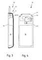
- the mobile telephone 10 comprises a rear housing part 11, which is also referred to as lower shell 11, at least one radiating element 12 of an antenna for transmitting and receiving communication signals, a circuit board 13 having the essential components and switching elements and for simplicity in the present example also the front housing part 13, the upper shell 13, represents.
- Upper shell 13 and lower shell 11 form a housing 23.
- FIGS. 14, a schematically illustrated battery module is designated.
- the radiating element 12 is the antenna Part of a so-called PIFA antenna (Planar Inverted F-Antenna).
- PIFA antenna Planar Inverted F-Antenna
- FIGS. 3 and 4 show a prior art mobile telephone with a multi-band antenna with an additional parasitic radiator element 15.
- This radiator element 15 is excited electromagnetically by the radiator element 12 and serves to transmit and receive communication signals in a further frequency band.
- radiator elements are connected via contacts 16 to an HF source on the circuit board 13.
- an inventive housing part is now shown, namely a removable bottom shell 17.
- the changing bottom shell 17 may also be a battery cover.
- the changing bottom shell 17 has correction members 18. These correction members are preferably formed as stamped parts, for example a sheet or a foil, and have spring contacts 19 for the galvanic connection to the radiator element 12 of the mobile radio telephone 10.
- the spring contacts 19 are formed as one-piece cohesive components of the correction elements 18 and have a directed to the radiator element 12 spring preload.
- the housing part 17 according to the invention is arranged on a mobile telephone 10 according to FIGS. 3 and 4.
- the galvanic contacting of the correction elements 18 with the radiating element 12 can be clearly seen via the spring contacts 19, wherein only the spring contacts 19 of the vertically arranged correction member 18 are shown.
- Fig. 6 shows in a rear view of the mobile phone 10 with mounted removable bottom shell 17 of FIG. 5. In the paper plane lying back part of the lower shell 17 is broken away to get a clear view of the interior of the mobile phone 10.
- the correction members 18 By means of the correction members 18, the influence of the changing bottom shell 17 of the mobile telephone 10 on the resonant frequency of the radiator elements 12 and 15 can be compensated.
- the horizontally arranged correction member 18 extends an arm 20 of the radiator element 12.
- the perpendicularly arranged correction member 18 bridges the clearly visible in Fig. 4, vertically arranged meandering region of the radiator element 12, so that the radiator element 12 is shortened in this area.
- the radiator elements 18 may be configured such that they also influence the resonant frequency of the parasitic radiator element 15.
- a galvanic connection not shown here, between at least one correction element 18 and the parasitic radiator element 15 is conceivable or an inductive and / or capacitive coupling of one or both radiator elements 18 to the parasitic radiator element 15 is possible.
- the radiator elements 18 then constitute, with respect to the parasitic radiator element 15, parasitic correction elements 18.
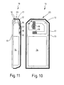
- the correction elements 21 are so-called parasitic correction elements 21, which are not galvanically but inductively and / or capacitively coupled to the radiator element 12 in order to compensate for the influences of the alternating bottom shell on the resonant frequency of the radiator element 12.
- FIGS. 10 and 11 once again show a mobile telephone 10 with the exchangeable lower shell 17 according to the invention as shown in FIGS. 8 and 9.
- FIGS. 8 and 9 there is a galvanic connection between the correction elements 18 and the radiator element 12.
- this takes place via spring contacts 22, which are formed by the radiator element 12.
- 9 and 11 it is clear that an exchangeable lower shell 17 with correction elements 18 or 21 as a function of the design of the radiating element 12 with or without spring contacts 22, correction elements 18 for a galvanic coupling or identically designed parasitic correction elements 21st can provide.
- the invention relates to an antenna for transmitting and receiving communication data in one or more frequency bands, which manages without special adaptation to the housing or certain housing parts.
- the adaptation to the housing or the housing parts is carried out by correction members which are arranged on the corresponding housing or housing part, so that the influences of the housing or the housing parts are compensated for the resonance frequency of the antenna. It is thus described an optimized on their transmit and receive power antenna with a small footprint, the housing-specific adjustment is done by means of correction elements.
Landscapes
- Engineering & Computer Science (AREA)
- Computer Networks & Wireless Communication (AREA)
- Support Of Aerials (AREA)
- Telephone Set Structure (AREA)
Applications Claiming Priority (1)
| Application Number | Priority Date | Filing Date | Title |
|---|---|---|---|
| DE102006002817A DE102006002817B4 (de) | 2006-01-19 | 2006-01-19 | Antenne für ein Telekommunikationsgerät |
Publications (1)
| Publication Number | Publication Date |
|---|---|
| EP1811599A1 true EP1811599A1 (fr) | 2007-07-25 |
Family
ID=37969673
Family Applications (1)
| Application Number | Title | Priority Date | Filing Date |
|---|---|---|---|
| EP06025067A Withdrawn EP1811599A1 (fr) | 2006-01-19 | 2006-12-05 | Antenne pour dispositif de telecommunication |
Country Status (5)
| Country | Link |
|---|---|
| US (1) | US7391380B2 (fr) |
| EP (1) | EP1811599A1 (fr) |
| CN (1) | CN101013898A (fr) |
| CA (1) | CA2571964A1 (fr) |
| DE (1) | DE102006002817B4 (fr) |
Families Citing this family (11)
| Publication number | Priority date | Publication date | Assignee | Title |
|---|---|---|---|---|
| US7812770B2 (en) | 2006-08-29 | 2010-10-12 | Research In Motion Limited | Mobile wireless communications device including an electrically conductive, electrically floating element and related methods |
| DE102009048334A1 (de) | 2009-10-06 | 2011-04-21 | Curt Niebling | 3D-Folienteil und Verfahren zu seiner Herstellung |
| TWM380586U (en) * | 2009-11-11 | 2010-05-11 | Wistron Corp | Antenna module and circuit board with the antenna module |
| CN102244525B (zh) * | 2010-05-14 | 2013-12-25 | 和硕联合科技股份有限公司 | 可携式电子装置 |
| TW201141179A (en) | 2010-05-14 | 2011-11-16 | Pegatron Corp | Portable electronic device |
| WO2013073334A1 (fr) * | 2011-11-17 | 2013-05-23 | ソニー株式会社 | Appareil électronique |
| CN103117968B (zh) * | 2013-01-25 | 2015-07-22 | 华中科技大学 | 一种基于电感耦合的无线通信补偿方法 |
| CN104253309B (zh) * | 2013-06-26 | 2018-08-17 | 中山市云创知识产权服务有限公司 | 无线通信装置 |
| US9634709B2 (en) | 2014-09-04 | 2017-04-25 | Apple Inc. | Removable electronic device case with supplemental antenna element |
| KR102245184B1 (ko) * | 2014-11-21 | 2021-04-27 | 삼성전자주식회사 | 안테나를 갖는 전자 장치 |
| US9654164B2 (en) | 2015-04-14 | 2017-05-16 | Apple Inc. | Removable electronic device case with supplemental wireless circuitry |
Citations (5)
| Publication number | Priority date | Publication date | Assignee | Title |
|---|---|---|---|---|
| EP0892459A1 (fr) * | 1997-07-08 | 1999-01-20 | Nokia Mobile Phones Ltd. | Structure d'antenne à double résonance pour plusieurs gammes de fréquences |
| US20020149523A1 (en) * | 2001-04-11 | 2002-10-17 | Chien-Hsing Fang | Antenna for an electronic device |
| WO2004062032A1 (fr) * | 2002-12-17 | 2004-07-22 | Sony Ericsson Mobile Communications Ab | Antennes planes a frequences de resonance multiples |
| US20040201527A1 (en) * | 2003-04-08 | 2004-10-14 | Hani Mohammad Bani | Variable multi-band planar antenna assembly |
| WO2005004277A1 (fr) * | 2003-07-01 | 2005-01-13 | Sk Telecom Co., Ltd. | Procede et appareil de diminution d'une exposition sar dans un dispositif de combine de communication |
Family Cites Families (9)
| Publication number | Priority date | Publication date | Assignee | Title |
|---|---|---|---|---|
| US5182568A (en) * | 1990-05-21 | 1993-01-26 | Motorola, Inc. | Loss cancellation element for an integral antenna receiver |
| JP4803881B2 (ja) * | 2001-01-16 | 2011-10-26 | パナソニック株式会社 | 携帯無線機の内蔵アンテナ |
| US6680703B1 (en) * | 2001-02-16 | 2004-01-20 | Sirf Technology, Inc. | Method and apparatus for optimally tuning a circularly polarized patch antenna after installation |
| DE10110982A1 (de) * | 2001-03-07 | 2002-09-19 | Siemens Ag | Mobilfunkgerät mit einem SAR-Werk-reduzierenden Korrekturelement |
| US6703974B2 (en) * | 2002-03-20 | 2004-03-09 | The Boeing Company | Antenna system having active polarization correlation and associated method |
| US7120399B2 (en) * | 2003-04-25 | 2006-10-10 | Broadcom Corporation | High speed CMOS transmit-receive antenna switch |
| DE10356495A1 (de) * | 2003-12-03 | 2005-07-28 | Siemens Ag | Haltevorrichtung zur Aufnahme eines tragbaren Funk-Kommunikationsgeräts mit einer Kopplerbaugruppe |
| US7132989B1 (en) * | 2005-05-04 | 2006-11-07 | Kyocera Wireless Corp. | Apparatus, system, and method for adjusting antenna characteristics using tunable parasitic elements |
| US7265724B1 (en) * | 2006-03-28 | 2007-09-04 | Motorola Inc. | Communications assembly and antenna assembly with a switched tuning line |
-
2006
- 2006-01-19 DE DE102006002817A patent/DE102006002817B4/de not_active Expired - Fee Related
- 2006-12-05 EP EP06025067A patent/EP1811599A1/fr not_active Withdrawn
- 2006-12-20 CA CA002571964A patent/CA2571964A1/fr not_active Abandoned
-
2007
- 2007-01-17 CN CNA2007100022867A patent/CN101013898A/zh active Pending
- 2007-01-18 US US11/655,045 patent/US7391380B2/en not_active Expired - Fee Related
Patent Citations (5)
| Publication number | Priority date | Publication date | Assignee | Title |
|---|---|---|---|---|
| EP0892459A1 (fr) * | 1997-07-08 | 1999-01-20 | Nokia Mobile Phones Ltd. | Structure d'antenne à double résonance pour plusieurs gammes de fréquences |
| US20020149523A1 (en) * | 2001-04-11 | 2002-10-17 | Chien-Hsing Fang | Antenna for an electronic device |
| WO2004062032A1 (fr) * | 2002-12-17 | 2004-07-22 | Sony Ericsson Mobile Communications Ab | Antennes planes a frequences de resonance multiples |
| US20040201527A1 (en) * | 2003-04-08 | 2004-10-14 | Hani Mohammad Bani | Variable multi-band planar antenna assembly |
| WO2005004277A1 (fr) * | 2003-07-01 | 2005-01-13 | Sk Telecom Co., Ltd. | Procede et appareil de diminution d'une exposition sar dans un dispositif de combine de communication |
Also Published As
| Publication number | Publication date |
|---|---|
| US20070164915A1 (en) | 2007-07-19 |
| CA2571964A1 (fr) | 2007-07-19 |
| DE102006002817A1 (de) | 2007-08-02 |
| DE102006002817B4 (de) | 2009-02-05 |
| US7391380B2 (en) | 2008-06-24 |
| CN101013898A (zh) | 2007-08-08 |
Similar Documents
| Publication | Publication Date | Title |
|---|---|---|
| DE60205720T2 (de) | Zwischen mehreren Frequenzbändern schaltbare Antenne für tragbare Endgeräte | |
| DE69830096T2 (de) | Antennenanordnung für kleines Funkkommunikationsgerät | |
| EP1329085B1 (fr) | Terminal de communication | |
| DE60316666T2 (de) | Mehrbandantenne mit Streifenleiter- und Schlitzstrukturen | |
| DE102007020501B4 (de) | Planarantenne sowie mobiles Kommunikationsendgerät, in welchem diese verwendet wird | |
| DE60218056T2 (de) | Drahtloses funkgerät | |
| DE69813357T2 (de) | Antenne für Telekommunikationsgeräte | |
| DE60109608T2 (de) | Antenne und funkgerät mit einer derartigen antenne | |
| DE60125947T2 (de) | Antennenanordnung und tragbares funkkommunikationsgerät | |
| DE60129475T2 (de) | Eingebaute Antenne für ein mobiles Funkgerät | |
| DE102019207821A1 (de) | Breitbandantennen für elektronische geräte | |
| DE69831375T2 (de) | Antennenkonnektor für einen tragbaren Funkgerät | |
| DE102008007258A1 (de) | Mehrband-Antenne sowie mobiles Kommunikationsendgerät, welches diese aufweist | |
| DE69428767T2 (de) | Einziehbare Antenne | |
| DE60302909T2 (de) | EMV-Vorrichtung eines drahtlosen Datenübertragungsgerätes | |
| DE102013108132A1 (de) | Antennensystem, Verfahren und mobiles Kommunikationsgerät | |
| DE102004059648A1 (de) | Antenne | |
| EP1307949A1 (fr) | Systeme d'antenne pour terminal de telecommunication mobile, notamment pour telephone portable | |
| DE102006002817B4 (de) | Antenne für ein Telekommunikationsgerät | |
| DE60212590T2 (de) | Antenne für tragbaren sender-/empfänger und tragbarer sender-/empfänger mit derselben | |
| DE102019000259A1 (de) | Antennenanordnung für anpassbare geräte | |
| DE10292326T5 (de) | Antennenvorrichtung und drahtlose Vorrichtung die diese verwendet | |
| DE60126989T2 (de) | Antenneneinrichtung und verfahren zur einstellung der antenneneinrichtung | |
| EP1237224A1 (fr) | Antenne et son procédé de fabrication | |
| DE10210341A1 (de) | Mehrband-Mikrowellenantenne |
Legal Events
| Date | Code | Title | Description |
|---|---|---|---|
| PUAI | Public reference made under article 153(3) epc to a published international application that has entered the european phase |
Free format text: ORIGINAL CODE: 0009012 |
|
| AK | Designated contracting states |
Kind code of ref document: A1 Designated state(s): AT BE BG CH CY CZ DE DK EE ES FI FR GB GR HU IE IS IT LI LT LU LV MC NL PL PT RO SE SI SK TR |
|
| AX | Request for extension of the european patent |
Extension state: AL BA HR MK YU |
|
| 17P | Request for examination filed |
Effective date: 20070928 |
|
| AKX | Designation fees paid |
Designated state(s): AT BE BG CH CY CZ DE DK EE ES FI FR GB GR HU IE IS IT LI LT LU LV MC NL PL PT RO SE SI SK TR |
|
| STAA | Information on the status of an ep patent application or granted ep patent |
Free format text: STATUS: THE APPLICATION IS DEEMED TO BE WITHDRAWN |
|
| 18D | Application deemed to be withdrawn |
Effective date: 20110701 |