EP1812254B1 - Achslaststeuersystem und achsstandeinstellsystem - Google Patents
Achslaststeuersystem und achsstandeinstellsystem Download PDFInfo
- Publication number
- EP1812254B1 EP1812254B1 EP05792395A EP05792395A EP1812254B1 EP 1812254 B1 EP1812254 B1 EP 1812254B1 EP 05792395 A EP05792395 A EP 05792395A EP 05792395 A EP05792395 A EP 05792395A EP 1812254 B1 EP1812254 B1 EP 1812254B1
- Authority
- EP
- European Patent Office
- Prior art keywords
- axle
- load
- control
- axles
- axle load
- Prior art date
- Legal status (The legal status is an assumption and is not a legal conclusion. Google has not performed a legal analysis and makes no representation as to the accuracy of the status listed.)
- Expired - Lifetime
Links
Images


Classifications
-
- B—PERFORMING OPERATIONS; TRANSPORTING
- B60—VEHICLES IN GENERAL
- B60G—VEHICLE SUSPENSION ARRANGEMENTS
- B60G17/00—Resilient suspensions having means for adjusting the spring or vibration-damper characteristics, for regulating the distance between a supporting surface and a sprung part of vehicle or for locking suspension during use to meet varying vehicular or surface conditions, e.g. due to speed or load
- B60G17/015—Resilient suspensions having means for adjusting the spring or vibration-damper characteristics, for regulating the distance between a supporting surface and a sprung part of vehicle or for locking suspension during use to meet varying vehicular or surface conditions, e.g. due to speed or load the regulating means comprising electric or electronic elements
- B60G17/0152—Resilient suspensions having means for adjusting the spring or vibration-damper characteristics, for regulating the distance between a supporting surface and a sprung part of vehicle or for locking suspension during use to meet varying vehicular or surface conditions, e.g. due to speed or load the regulating means comprising electric or electronic elements characterised by the action on a particular type of suspension unit
-
- B—PERFORMING OPERATIONS; TRANSPORTING
- B60—VEHICLES IN GENERAL
- B60G—VEHICLE SUSPENSION ARRANGEMENTS
- B60G17/00—Resilient suspensions having means for adjusting the spring or vibration-damper characteristics, for regulating the distance between a supporting surface and a sprung part of vehicle or for locking suspension during use to meet varying vehicular or surface conditions, e.g. due to speed or load
- B60G17/015—Resilient suspensions having means for adjusting the spring or vibration-damper characteristics, for regulating the distance between a supporting surface and a sprung part of vehicle or for locking suspension during use to meet varying vehicular or surface conditions, e.g. due to speed or load the regulating means comprising electric or electronic elements
- B60G17/0152—Resilient suspensions having means for adjusting the spring or vibration-damper characteristics, for regulating the distance between a supporting surface and a sprung part of vehicle or for locking suspension during use to meet varying vehicular or surface conditions, e.g. due to speed or load the regulating means comprising electric or electronic elements characterised by the action on a particular type of suspension unit
- B60G17/0155—Resilient suspensions having means for adjusting the spring or vibration-damper characteristics, for regulating the distance between a supporting surface and a sprung part of vehicle or for locking suspension during use to meet varying vehicular or surface conditions, e.g. due to speed or load the regulating means comprising electric or electronic elements characterised by the action on a particular type of suspension unit pneumatic unit
-
- B—PERFORMING OPERATIONS; TRANSPORTING
- B60—VEHICLES IN GENERAL
- B60G—VEHICLE SUSPENSION ARRANGEMENTS
- B60G17/00—Resilient suspensions having means for adjusting the spring or vibration-damper characteristics, for regulating the distance between a supporting surface and a sprung part of vehicle or for locking suspension during use to meet varying vehicular or surface conditions, e.g. due to speed or load
- B60G17/02—Spring characteristics, e.g. mechanical springs and mechanical adjusting means
- B60G17/04—Spring characteristics, e.g. mechanical springs and mechanical adjusting means fluid spring characteristics
- B60G17/052—Pneumatic spring characteristics
-
- G—PHYSICS
- G01—MEASURING; TESTING
- G01G—WEIGHING
- G01G19/00—Weighing apparatus or methods adapted for special purposes not provided for in the preceding groups
- G01G19/08—Weighing apparatus or methods adapted for special purposes not provided for in the preceding groups for incorporation in vehicles
-
- B—PERFORMING OPERATIONS; TRANSPORTING
- B60—VEHICLES IN GENERAL
- B60G—VEHICLE SUSPENSION ARRANGEMENTS
- B60G2400/00—Indexing codes relating to detected, measured or calculated conditions or factors
- B60G2400/25—Stroke; Height; Displacement
- B60G2400/252—Stroke; Height; Displacement vertical
-
- B—PERFORMING OPERATIONS; TRANSPORTING
- B60—VEHICLES IN GENERAL
- B60G—VEHICLE SUSPENSION ARRANGEMENTS
- B60G2400/00—Indexing codes relating to detected, measured or calculated conditions or factors
- B60G2400/60—Load
- B60G2400/61—Load distribution
Definitions
- the present invention relates to an axle load control system and method for a load carrying truck according to the preambles of claims 1 and 8. Furthermore, the invention relates to a system and a method for adjusting the theoretical wheel base according to the preambles of claims of 12 and 18. The invention is applicable to both semi-trailer tractors and rigid trucks.
- Load carrying trucks are generally well adapted and specified for their particular missions and for particular kinds of loads. Modern air suspension systems are smoother and more controllable than more traditional spring suspension systems. Traditionally, however, trucks are optimized for an even axle load distribution when the vehicle is fully loaded. In this situation, the centre of gravity of the truck is generally conveniently located at or near the longitudinal centre of the truck and each axle is loaded well within legal limits for axle load. Thus, once fully loaded, a truck normally starts its trip with an even and road-legal axle load distribution. As long as the full load is unloaded at the same final destination, the truck will maintain this even axle load distribution throughout its trip.
- the centre of gravity of the truck is usually shifted in a forward direction since the trailer or other load space is commonly successively unloaded from the rear of the truck. This means that, although the total weight of the vehicle is now lower than it was at the start of the trip, its forward distribution in the truck may lead to an undesired overload of the front axle of the truck. This undesired overload may of course be corrected by repositioning the remaining load in the truck rearwards, but this is rarely done in practice.
- a minimum wheel base could be stipulated so as to avoid overload of a road or bridge.
- US6203045 relates to a system for automatically distributing weight within a heavy duty vehicle.
- the system includes a plurality of sensors that provide information indicative of weight at each of the axles.
- the position of an attachment disc 40 with reference to the cab is automatically adjustable.
- the attachment disc 40 serves to connect the trailer to the cab.
- a first object of the invention is to provide a load control system of the type mentioned in the introduction, by which system an undesired overload of an axle of a truck can be avoided.
- control processor is arranged to control the wheel suspension system so as to effect an Individual adjustment of the suspension characteristics for the rear axles in such a way that excess axle load on the front axle is transferred to one or more of the rear axles.
- control processor is arranged to continuously compare said actual axle load values with said predefined maximum allowable axle load value for each axle, and to automatically continuously control the wheel suspension system in the described manner.
- control processor is arranged to continuously compare said actual axle load values with said predefined maximum allowable axle load value for each axle, and to a driver indicate the need to control the wheel suspension system in the described manner, said indication being communicated to the driver via a driver interface means provided with manual control means for effecting said individual adjustment of the suspension characteristics for each axle in predefined discrete steps.
- a driver interface means provided with manual control means for effecting said individual adjustment of the suspension characteristics for each axle in predefined discrete steps.
- the wheel suspension system is an air suspension system comprising suspension units in the form of air bellows, and that said load sensor means are adapted to detect the air pressure in said air bellows.
- control processor is further adapted to receive and process input from an electronic brake system of the truck, said input adding temporary limitations to the transferable loads between axles due to present dynamic load conditions on each axle.
- the invention also discloses a method of axle load control for a load-carrying truck having a front axle and two or more rear axles, using a system comprising a wheel suspension system with a suspension control processor and a load sensor means arranged at each of said axles for detecting one or more load indication parameters, said load sensor means providing said parameters to said suspension control processor which translates the parameters into actual axle load values for the individual axles.
- the method is especially characterized in that the control processor compares said actual axle load values with a predefined maximum allowable axle load value for each axle, and controls the wheel suspension system so as to individually adjust the suspension characteristics for each axle in such a way that excess axle load on an overloaded axle is transferred to one or more of the remaining axles, thereby adjusting the theoretical wheelbase of the truck.
- a further object of the invention is to provide a system of the type mentioned in the introduction, by which system a desired theoretical wheel base of a truck can be obtained.
- This problem is solved by means of a system according to claim 12.
- the wheel base of a truck can be adjusted by transferring load from one rear axle to another.
- the suspension characteristics of at least one axle the load distribution is altered, and thus the theoretical wheel base is adjusted.
- the theoretical wheel base can be adjusted by adjustment of the suspension characteristics of a front axle if the truck is provided with two front axles.
- the second aspect of the invention also provides a method for adjusting the theoretical wheel base according to claim 18.
- reference numeral 1 generally denotes a load-carrying truck using an axle load control system and/or a wheel base adjustment system according to the invention.
- the truck is represented by a three-axle 6X4 or 6X2 semi-trailer tractor.
- the truck has a front axle 2 and two rear axles 4, 6 arranged in a tandem configuration, wherein both rear axles are commonly suspended on a pivoting frame (not shown) so that wheels 8 of both rear axles 4, 6 are both constantly in contact with the road.
- the invention is also applicable on any other rear axle combination, such as a boogie combination, wherein one of the rear axles 4, 6 may be lifted so as to lift the wheels 8 of this axle out of road contact if necessary.
- Fig. 1 illustrates the theoretical wheelbase TWB at a 50/50 split load distribution on the rear axles 4, 6, i.e. where each rear axle 4, 6 carries 50% of the load on the rear axles.
- This is the most common fixed load distribution on known trucks today, and in this particular embodiment of the invention, it is the default start-up setting of the axle load control system of the invention.
- a so called king-pin for towing the semi-trailer (not shown) is positioned in a fifth wheel 12 halfway between the two rear axles 4, 6 and the theoretical wheelbase will in this case - with a 50/50 split load distribution as described above - extend back to the longitudinal position of the fifth wheel 12.
- the diagram in Fig. 2 schematically illustrates the systems according to the invention.
- the axle load control system as well as the wheel base adjustment system is preferably integrated with a wheel suspension system with a suspension control processor 12.
- the wheel suspension system is an air suspension system comprising suspension units 14 in the form of air bellows, at least on the two rear axles 4, 6. It should be noted that the invention is not limited to the use of such air bellows as suspension units, but that other types of suspension units 14 like hydraulic oil-dampened cylinders (not shown) may also be used.
- Load sensor means 16 are arranged at each of said axles 2, 4, 6 for detecting one or more load indication parameters. The load sensor means 16 provide these parameters to the suspension control processor 12, which may translate the parameters into actual axle load values for the individual axles 2, 4, 6.
- the load sensor means 16 - at least for the two rear axles 4, 6 are adapted to detect the air pressure in the suspension units 14.
- the load sensor means 16 on the front axle will also detect the air pressure in the suspension units 14.
- the load sensor means 16 will detect the load on the front axle depending on the type of sensor used. It is e.g. possible to use a sensor that transforms the height information of the front axle into a load value.
- the suspension units 14 are supplied with pressurized air from an onboard source of compressed air (not shown) via pressurized air supply conduits 18.
- the load sensor means 16 are connected to the control processor 12 by means of sensor signal lines 20.
- control signal lines 22 are arranged from the control processor 12 to each suspension unit 14.
- the control processor 12 is in the shown embodiment connected to a trailer communication data bus 24, which communicates the type of semi-trailer (not shown in Fig. 2 ) currently coupled to the tractor etc.
- An essential feature according to the first aspect of the invention is that the control processor 12 is arranged to compare the actual axle load values with a predefined maximum allowable axle load value for each axle. Then the control processor 12 controls - or indicates to a driver the need to control - the wheel suspension system so as to effect an individual adjustment of the suspension characteristics for each axle 2, 4, 6. This is made in such a way that excess axle load on an overloaded axle is transferred to one or more of the remaining axles 2, 4, 6, thereby adjusting the theoretical wheelbase TWB of the truck 1.
- the term excess axle load here means the axle load, which exceeds a maximum allowed axle load P max .
- the axle load control system thus enables an adjustment of the theoretical wheelbase of the truck so as to maintain an optimum axle load distribution for any load configuration.
- control processor 12 is arranged so as to effect an individual adjustment of the suspension characteristics for the rear axles 4, 6 only, still in such a way that excess axle load on the front axle 2 is transferred to one or more of the rear axles 4, 6.
- control processor 12 is arranged to continuously compare said actual axle load values with said predefined maximum allowable axle load value P max for each axle, and to automatically continuously control the wheel suspension system in the described manner.
- the control processor 12 is likewise arranged to continuously compare said actual axle load values with the predefined maximum allowable axle load value P max for each axle 2, 4, 6.
- the axle load control system indicate the need to control the wheel suspension system in the described manner to a driver. This indication may suitably be communicated to the driver via a driver interface means 26 shown as an optional feature in the diagram of Fig. 2 .
- the driver interface means 26 is provided with manual control means 28 - here in the form of buttons for choosing various fixed axle load distribution settings - for effecting said individual adjustment of the suspension characteristics for each axle 2, 4, 6 in predefined discrete steps.
- the manual control means 28 include buttons for the following distribution splits of axle load between the two rear axles 4, 6: "60/40", “80/20”, “RESET 50/50”, “40/60” and “80/20”, where the numbers indicate percentages of total axle load on the two rear axles 4, 6.
- the driver interface means 26 is also provided with a visual display 30, which in Fig. 2 displays a message to the driver in the form of "CAUTION! FRONT AXLE OVERLOAD". The driver may then use the manual control means 30 - i.e. said buttons - to choose an appropriate adjustment setting in order to relieve the front axle 2.
- the truck 1 is a three-axle semi-trailer tractor 1 having a front axle 2 and two rear axles 4, 6.
- the individual adjustment is made in a default first discrete step, wherein the load on the two rear axles 4, 6 is distributed with 50% on each rear axle (i.e. a so called 50/50 split), and a second discrete step, wherein the load on the two rear axles 4, 6 is distributed with 60% on the most forward rear axle 4 and 40% on the most rearward rear axle 6 (i.e. a so called 60/40 split).
- This example - together with examples of continuous automatic adjustment - will be described in further detail below.
- a similar driver interface means may be used also in the case where the individual adjustment is made automatically by the axle load control system of the invention. In such a case, the driver interface means may continually display the current adjustment setting for the driver.
- the driver interface means 26 may also be integrated In a general suspension control display of the truck 1.
- control processor 12 is further adapted to receive and process input from an electronic brake system (EBS) of the truck 1.
- EBS electronic brake system
- the electronic brake system is not shown in the diagram of Fig. 2 , although an EBS-signal line 32 is schematically indicated to the right in the figure, leading to the control processor 12.
- the input from the electronic brake system add temporary limitations to the transferable loads between axles 2, 4, 6 due to present dynamic load conditions on each axle 2, 4, 6.
- the invention also discloses a method of axle load control using the system described above.
- the method is especially characterized in that the control processor 12 compares said actual axle load values with a predefined maximum allowable axle load value P max for each axle, and controls the wheel suspension system so as to individually adjust the suspension characteristics for each axle 2, 4, 6 in such a way that excess axle load on an overloaded axle is transferred to one or more of the remaining axles, thereby adjusting the theoretical wheelbase TWB of the truck 1.
- the truck 1 here consists of a tractor and a semi-trailer 34.
- Fig. 3 shows the truck 1 in a fully loaded condition on its way to a first destination.
- the centre of gravity CG is located approximately half way along the length of the truck combination and the axle load is distributed evenly with a default 50/50 split on the two rear axles 4, 6 of the tractor.
- the axle load P on the front axle 2 of the tractor is lower than, or equal to the predefined maximum allowable axle load value P max for the front axle 2.
- the tractor has a first theoretical wheelbase TWB 1.
- the control processor 12 now controls the wheel suspension system so as to effect an individual adjustment of the suspension characteristics for the rear axles 4, 6 in such a way that the excess axle load on the front axle 2 is transferred to the rear axles 4, 6 of the tractor.
- the axle load control system automatically compensates for the front axle overload by altering the load distribution from a 50/50 split on the rear axles to a 60/40 split, whereby the theoretical wheelbase TWB is decreased from TWB 1 to TWB 2.
- the axle load control system has effectively decreased the theoretical wheelbase TWB of the tractor.
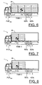
- the truck 1 here consists of a rigid truck having a load compartment 36.
- This example is similar to the first example and thus Fig. 6 shows the truck 1 in a fully loaded condition on its way to a first destination.
- the centre of gravity CG is located approximately half way along the length of the truck 1 and the axle load is distributed evenly with a default 50/50 split on the two rear axles 4, 6.
- the axle load P on the front axle 2 is lower than, or equal to the predefined maximum allowable axle load value P max for the front axle 2.
- the truck has a first theoretical wheelbase TWB 1.
- the control processor 12 now controls the wheel suspension system so as to effect an individual adjustment of the suspension characteristics for the rear axles 4, 6 in such a way that the excess axle load on the front axle 2 is transferred to the rear axles 4, 6 of the tractor.
- the axle load control system automatically compensates for the front axle overload by altering the load distribution from a 50/50 split on the rear axles to a 60/40 split, whereby the theoretical wheelbase TWB is decreased from TWB 1 to TWB 2.
- the axle load control system has effectively decreased the theoretical wheelbase TWB of the truck 1.
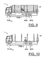
- the truck 1 here consists of a three-axle rigid timber truck.
- the axle load control system has effected a 40/60 split load distribution on the rear axles 4, 6 in order to accommodate for a heavy rear-mounted timber crane 38.
- the truck has a first theoretical wheelbase TWB 1.
- Fig. 10 shows the timber truck of Fig. 9 in an unloaded condition, wherein the axle load control system according to the invention has compensated for a rear shift of the centre of gravity CG of the truck 1 in said unloaded condition due to the heavy rear-mounted crane 38.
- a 20/80-split load distribution has been effected on the rear axles 4, 6.
- the truck has a longer theoretical wheelbase TWB 2.
- the invention is by no means limited to the embodiments described above, and may be varied freely within the scope of the appended claims.
- the trucks may be of a wide variety of types, having three or more axles.
- the invention is moreover suitable for busses, especially for large touring busses with two rear axles, where a proper load distribution is necessary to avoid an overload on the front axle.
- the invention is also suitable for trailers and for construction equipment vehicles.
Landscapes
- Engineering & Computer Science (AREA)
- Mechanical Engineering (AREA)
- Physics & Mathematics (AREA)
- General Physics & Mathematics (AREA)
- Vehicle Body Suspensions (AREA)
- Hydraulic Control Valves For Brake Systems (AREA)
- Body Structure For Vehicles (AREA)
Claims (11)
- Achslaststeuersystem für einen Lastkraftwagen (1) mit einer Vorderachse (2) und zwei oder mehreren Hinterachsen (4, 6), wobei das System umfasst:- ein Radaufhängungssystem mit einem Aufhängungssteuerungsprozessor (12), wobei das Radaufhängungssystem ein Luftfederungssystem mit Aufhängungseinheiten (14) in Form von Luftbälgen ist,- Lastsensoreinrichtungen (16), die an jeder der Achsen (2, 4, 6) zur Erfassung einer oder mehrerer Lastindikationsparameter anordbar sind, wobei die Lastsensoreinrichtungen (16) die Parameter dem Aufhängungssteuerungsprozessor (12) bereitstellen, der die Parameter in tatsächliche Achslastwerte für die individuellen Achsen (2, 4, 6) übersetzt,
dadurch gekennzeichnet,
dass die Lastsensoreinrichtungen (16) zur Erfassung der Lastindikationsparameter durch Messung des Luftdrucks in den Luftbälgen (14) konfiguriert sind,
dass der Steuerungsprozessor (12) so konfiguriert ist, dass er die tatsächlichen Achslastwerte mit einem vorherbestimmten maximal erlaubten Achslastwert (Pmax) für jede Achse (2, 4, 6) vergleicht und das Radaufhängungssystem so steuert oder dem Fahrer anzeigt, dass das Radaufhängungssystem so gesteuert werden muss, dass eine individuelle Einstellung der Aufhängungseigenschaften für jede Achse (2, 4, 6) durch Steuerung des Luftdrucks in wenigstens einem der Luftbälge (14) so bewirkt wird, dass eine übermäßige Achslast an einer überbelasteten Achse (2, 4, 6) auf eine oder mehrere der verbleibenden Achsen (2, 4, 6) übertragen wird,
wodurch der theoretische Radstand (TWB) des Lastkraftwagens (1) eingestellt wird. - Achslaststeuersystem nach Anspruch 1, dadurch gekennzeichnet, dass der Steuerungsprozessor (12) so konfiguriert ist, dass er das Radaufhängungssystem so steuert, dass eine individuelle Einstellung der Aufhängungseigenschaften der Hinterachsen (4, 6) so bewirkt wird, dass eine übermäßige Achslast an der Vorderachse (2) auf eine oder mehrere der Hinterachsen (4, 6) übertragen wird.
- Achslaststeuersystem nach Anspruch 1 oder 2, dadurch gekennzeichnet, dass der Steuerungsprozessor (12) so konfiguriert ist, dass er fortlaufend die tatsächlichen Achslastwerte mit dem vorherbestimmten maximal erlaubten Achslastwert (Pmax) für jede Achse (2, 4, 6) vergleicht und automatisch fortlaufend das Radaufhängungssystem auf die beschriebene Weise steuert.
- Achslaststeuersystem nach Anspruch 1 oder 2, dadurch gekennzeichnet, dass der Steuerungsprozessor (12) so konfiguriert ist, dass er fortlaufend die tatsächlichen Achslastwerte mit dem vorherbestimmten maximal erlaubten Achslastwert (Pmax) für jede Achse (2, 4, 6) vergleicht und einen Fahrer darauf hinweist, dass er das Radaufhängungssystem auf die beschriebene Weise steuern muss, wobei der Hinweis dem Fahrer über eine Fahrerschnittstelleneinrichtung (26) mitgeteilt wird, die mit einer manuellen Steuereinrichtung (28) zur Bewirkung der individuellen Einstellung der Aufhängungseigenschaften jeder Achse (2, 4, 6) in vorherbestimmten diskreten Schritten versehen ist.
- Achslaststeuersystem nach Anspruch 4, bei dem der Lastkraftwagen ein dreiachsiges Sattelschlepperzugfahrzeug mit einer Vorderachse und zwei Hinterachsen ist, dadurch gekennzeichnet, dass die individuellen Einstellungen gemacht werden in- einem ersten diskreten Schritt, in dem die Last der zwei Hinterachsen auf 50% an jeder Hinterachse verteilt wird, und- einem zweiten diskreten Schritt, in dem die Last an den zwei Hinterachsen zu 60% auf die vorderste Hinterachse und zu 40% auf die hinterste Hinterachse übertragen wird.
- Achslaststeuersystem nach einem der vorhergehenden Ansprüche, dadurch gekennzeichnet, dass das Radaufhängungssystem ein Luftfederungssystem mit Aufhängungseinheiten (14) in Form von Luftbälgen ist, und dass die Lastsensoreinrichtungen (16) zur Erfassung des Luftdrucks in den Luftbälgen (14) ausgelegt sind.
- Achslaststeuersystem nach einem der vorhergehenden Ansprüche, dadurch gekennzeichnet, dass der Steuerungsprozessor (12) außerdem zum Empfang und zur Verarbeitung eines Eingangs von einem elektronischen Bremssystem des Lastkraftwagens (1) ausgelegt ist, wobei der Eingang temporäre Begrenzungen der übertragbaren Lasten zwischen Achsen (2, 4, 6) aufgrund vorhandener dynamischer Lastbedingungen an jeder Achse (2, 4, 6) hinzufügt.
- Verfahren zur Achslaststeuerung bei einem Lastkraftwagen (1) mit einer Vorderachse (2) und zwei oder mehreren Hinterachsen (4, 6), wobei ein System verwendet wird, das ein Radaufhängungssystem mit einem Aufhängungssteuerungsprozessor (12) und eine Lastsensoreinrichtung (16) umfasst, die an jeder der Achsen zur Erfassung einer oder mehrerer Lastindikationsparameter angeordnet ist, wobei das Radaufhängungssystem ein Luftfederungssystem ist und die Lastsensoreinrichtungen (16) dem Aufhängungssteuerungsprozessor (12) die Parameter bereitstellen, der die Parameter in tatsächliche Achslastwerte für die individuellen Achsen (2, 4, 6) übersetzt, dadurch gekennzeichnet, dass eine Luftfederung mit Aufhängungseinheiten (14) in Form von Luftbälgen verwendet wird, und die Lastindikationsparameter durch Messung des Luftdrucks in den Luftbälgen (14) erfasst werden, und dass der Steuerungsprozessor (12) die tatsächlichen Achslastwerte mit einem vorherbestimmten maximal erlaubten Achslastwert (Pmax) für jede Achse (2, 4, 6) vergleicht, und das Radaufhängungssystem so steuert, dass die Aufhängungseigenschaften für jede Achse (2, 4, 6) durch Steuerung des Luftdrucks in wenigstens einem Luftbalg (14) individuell so eingestellt werden, dass eine übermäßige Achslast an einer überbelasteten Achse (2, 4, 6) auf eine oder mehrere der verbleibenden Achsen (2, 4, 6) übertragen wird, wodurch der theoretische Radstand (TWB) des Lastkraftwagens (1) eingestellt wird.
- Verfahren zur Achslaststeuerung nach Anspruch 8, dadurch gekennzeichnet, dass der Steuerungsprozessor (12) die tatsächlichen Achslastwerte mit dem vorherbestimmten maximal erlaubten Achslastwert (Pmax) fortlaufend für jede Achse (2, 4, 6) vergleicht und das Radaufhängungssystem auf die beschriebene Weise automatisch fortlaufend steuert.
- Verfahren zur Achslaststeuerung nach Anspruch 8, dadurch gekennzeichnet, dass der Steuerungsprozessor (12) fortlaufend die tatsächlichen Achslastwerte mit dem vorherbestimmten maximalen erlaubten Achslastwert (Pmax) für jede Achse (2, 4, 6) vergleicht und den Fahrer darauf hinweist, dass das Radaufhängungssystem auf die beschriebene Weise gesteuert werden muss, wobei der Hinweis dem Fahrer über eine Fahrerschnittstelleneinrichtung (26) mitgeteilt wird, die mit einer manuellen Steuereinrichtung (28) zur Bewirkung der individuellen Einstellung der Aufhängungseigenschaften für jede Achse (2, 4, 6) in vorherbestimmten diskreten Schritten versehen ist.
- Verfahren zur Achslaststeuerung nach einem der Ansprüche 8 bis 10, dadurch gekennzeichnet, dass der Steuerungsprozessor (12) außerdem einen Eingang von einem elektronischen Bremssystem des Lastkraftwagens empfängt und verarbeitet, wobei der Eingang temporäre Begrenzungen der übertragbaren Lasten zwischen Achsen aufgrund vorhandener dynamischer Lastbedingungen an jeder Achse (2, 4, 6) hinzufügt.
Applications Claiming Priority (2)
| Application Number | Priority Date | Filing Date | Title |
|---|---|---|---|
| SE0402543A SE529962C2 (sv) | 2004-10-18 | 2004-10-18 | System och förfarande för axellastreglering för en lastbärande lastbil |
| PCT/SE2005/001511 WO2006043872A1 (en) | 2004-10-18 | 2005-10-11 | An axle load control system and a wheel base adjustment system |
Publications (3)
| Publication Number | Publication Date |
|---|---|
| EP1812254A1 EP1812254A1 (de) | 2007-08-01 |
| EP1812254A4 EP1812254A4 (de) | 2009-11-18 |
| EP1812254B1 true EP1812254B1 (de) | 2011-06-29 |
Family
ID=33448668
Family Applications (1)
| Application Number | Title | Priority Date | Filing Date |
|---|---|---|---|
| EP05792395A Expired - Lifetime EP1812254B1 (de) | 2004-10-18 | 2005-10-11 | Achslaststeuersystem und achsstandeinstellsystem |
Country Status (8)
| Country | Link |
|---|---|
| US (1) | US20070296173A1 (de) |
| EP (1) | EP1812254B1 (de) |
| CN (1) | CN101056773B (de) |
| AT (1) | ATE514581T1 (de) |
| BR (1) | BRPI0516500A (de) |
| DK (1) | DK1812254T3 (de) |
| SE (1) | SE529962C2 (de) |
| WO (1) | WO2006043872A1 (de) |
Families Citing this family (38)
| Publication number | Priority date | Publication date | Assignee | Title |
|---|---|---|---|---|
| SE529218C2 (sv) * | 2005-10-26 | 2007-06-05 | Volvo Lastvagnar Ab | System och förfarande för reglering av axellastfördelningsförhållandet på ett fordon med två framaxlar |
| GB0623802D0 (en) * | 2006-11-29 | 2007-01-10 | Brown Duncan | An arrangement of interconnected devices or system to indicate loading state or overload of the axles on a vehicle |
| EP2065689A1 (de) * | 2007-11-28 | 2009-06-03 | Iveco S.p.A. | Verfahren und Vorrichtung zur Erkennung einer Fahrzeugüberlastung, insbesondere für Nutz- oder Industriefahrzeuge |
| GB2467978B (en) * | 2009-02-24 | 2013-06-12 | Knorr Bremse Systeme | Apparatus for monitoring the status of a movable load carrying member mounted on a vehicle |
| CA2714148A1 (en) * | 2009-08-31 | 2011-02-28 | Andriy Hapyuk | System and method for determining whether the weight of a vehicle equipped with an air-ride suspension exceeds predetermined roadway weight limitations |
| US20130297154A1 (en) * | 2011-01-17 | 2013-11-07 | Volvo Group North America, Llc | Tractor trailer gap control system |
| CN102431410B (zh) * | 2011-12-21 | 2013-12-11 | 中联重科股份有限公司 | 车辆的悬挂分组控制系统及悬挂分组控制方法 |
| US8573680B2 (en) | 2012-01-13 | 2013-11-05 | Paccar Inc | Vehicle trailer with improved aerodynamics |
| US9481415B2 (en) * | 2012-02-10 | 2016-11-01 | Compagnie Generale Des Etablissements Michelin | Vehicle fuel economy by optimizing effective rolling tire resistance |
| WO2013190570A1 (en) * | 2012-06-22 | 2013-12-27 | Volvo India Pvt Ltd | Load distribution system and method |
| CN102785664B (zh) * | 2012-08-13 | 2016-01-20 | 徐州重型机械有限公司 | 起重机及根据轴荷控制超载车辆行驶的系统和方法 |
| SE537724C2 (sv) * | 2012-10-29 | 2015-10-06 | Scania Cv Ab | Förfarande och system för lastöverföring i ett fordon |
| US8987615B2 (en) | 2013-02-27 | 2015-03-24 | American Axle & Manufacturing, Inc. | Axle load monitoring system (ALMS) |
| US10611206B2 (en) | 2013-03-13 | 2020-04-07 | Hendrickson Usa, L.L.C. | Air suspension control system |
| CN103287206A (zh) * | 2013-06-14 | 2013-09-11 | 安徽江淮汽车股份有限公司 | 一种卡车底盘车桥布置形式 |
| US9227476B2 (en) | 2013-10-31 | 2016-01-05 | Bridgestone Americas Tire Operations, Llc | Systems and methods for automated air suspension pressure drop |
| WO2015134231A1 (en) | 2014-03-04 | 2015-09-11 | Hendrickson Usa, Llc | Parking brake interlock for automatic lift axle |
| US9522582B2 (en) * | 2014-05-09 | 2016-12-20 | Ford Global Technologies, Llc | Systems and methods for setting front axle load restoration |
| US10870325B2 (en) | 2014-12-16 | 2020-12-22 | Aktv8 LLC | System and method for vehicle stabilization |
| US10675936B2 (en) | 2014-12-16 | 2020-06-09 | Atv8 Llc | System and method for vehicle stabilization |
| US10160278B2 (en) | 2014-12-16 | 2018-12-25 | Aktv8 LLC | System and method for vehicle stabilization |
| JP6760940B2 (ja) | 2014-12-16 | 2020-09-23 | エイ・ケイ・ティ・ブイ・8・リミテッド・ライアビリティ・カンパニーAktv8 Llc | 電子制御式車両サスペンションシステムおよびその製造方法 |
| WO2016131982A1 (en) * | 2015-02-20 | 2016-08-25 | Volvo Truck Corporation | A method for controlling a wheel axle load of a vehicle wheel axle |
| US9943963B2 (en) * | 2016-04-12 | 2018-04-17 | Fetch Robotics, Inc. | System and method for determining and promoting safety of a robotic payload |
| WO2018049433A2 (en) | 2016-09-06 | 2018-03-15 | Aktv8 LLC | Tire management system and method |
| WO2018049475A1 (en) * | 2016-09-15 | 2018-03-22 | Terex Australia Pty Ltd | Crane counterweight and suspension |
| FR3056452A1 (fr) * | 2016-09-29 | 2018-03-30 | Compagnie Generale Des Etablissements Michelin | Procede d'evaluation de la charge dynamique portee par un pneumatique par la mesure de la pression et de l'acceleration longitudinale |
| US10029529B2 (en) * | 2016-11-28 | 2018-07-24 | Bendix Commercial Vehicle Systems Llc | Apparatus and method for determining load weight |
| TR201617620A2 (tr) * | 2016-12-01 | 2018-06-21 | Ford Otomotiv Sanayi As | Arka süspansi̇yon yükünden dorse durum tahmi̇n yöntemi̇ |
| WO2018129192A2 (en) * | 2017-01-04 | 2018-07-12 | Aktv8 LLC | System and method for vehicle load management |
| GB2565851B (en) * | 2017-08-25 | 2022-05-04 | Haldex Brake Prod Ab | Braking system |
| CN108177494A (zh) * | 2018-01-16 | 2018-06-19 | 徐州重型机械有限公司 | 一种车辆用悬挂系统及其模块化车辆 |
| FI129170B (en) | 2020-07-15 | 2021-08-31 | Nt Liftec Oy | Lift transport trolley and procedure for determining the load weight |
| US11821781B2 (en) * | 2020-07-20 | 2023-11-21 | Progress Mfg. Llc | Apparatus and method for determining weight distribution |
| US11945277B2 (en) | 2021-09-29 | 2024-04-02 | Ford Global Technologies, Llc | Methods and apparatus to use front load estimates for body control |
| CN114527705A (zh) * | 2022-02-17 | 2022-05-24 | 河南省奥瑞环保科技股份有限公司 | 一种仪器仪表节能控制管理系统 |
| CN116394691B (zh) * | 2023-04-23 | 2024-02-06 | 小米汽车科技有限公司 | 拖车控制方法、装置及车辆 |
| EP4592103A1 (de) * | 2024-01-29 | 2025-07-30 | Volvo Truck Corporation | Verfahren zur änderung des rollwiderstandes eines fahrzeugs |
Family Cites Families (12)
| Publication number | Priority date | Publication date | Assignee | Title |
|---|---|---|---|---|
| US3871677A (en) * | 1971-10-04 | 1975-03-18 | Oshkosh Truck Company | Heavy duty truck suspension |
| US3920283A (en) * | 1974-08-26 | 1975-11-18 | Lear Siegler Inc | Brake responsive load transfer apparatus and method |
| US4789038A (en) * | 1987-03-12 | 1988-12-06 | Structural Instrumentation, Inc. | Axle weight distribution controller |
| US4854407A (en) * | 1988-08-30 | 1989-08-08 | Wagner William C | System for measuring air pressure on drive axles of road tractor trailers and load distribution |
| US5025877A (en) * | 1989-07-21 | 1991-06-25 | Daniel Assh | Load distribution system for road vehicles having wheel axles supported by pneumatic suspension |
| US5167289A (en) * | 1991-04-30 | 1992-12-01 | Stevenson David L | Air spring load monitoring system |
| JPH09109645A (ja) * | 1995-10-20 | 1997-04-28 | Nissan Diesel Motor Co Ltd | エアサスペンション車の軸重配分装置 |
| US6203045B1 (en) * | 1998-11-23 | 2001-03-20 | Meritor Heavy Vehicle Systems, Llc | System for automatically controlling weight distribution among truck axles |
| JP2001213130A (ja) * | 2000-02-01 | 2001-08-07 | Hino Motors Ltd | 軸荷重調節装置 |
| DE10029332B4 (de) * | 2000-06-20 | 2007-05-24 | Continental Aktiengesellschaft | Messung des Beladungszustandes eines Kraftfahrzeuges |
| IL159046A0 (en) * | 2001-05-25 | 2004-05-12 | Haldex Brake Corp | Trailing arm suspension and height control system with motorized valve therefor |
| DE10227453A1 (de) * | 2002-06-20 | 2004-01-08 | Wabco Gmbh & Co. Ohg | Einrichtung und Verfahren zur Steuerung von Betriebsfunktionen bei vollluftgefederten Nutzkraftwagen |
-
2004
- 2004-10-18 SE SE0402543A patent/SE529962C2/sv not_active IP Right Cessation
-
2005
- 2005-10-11 BR BRPI0516500-8A patent/BRPI0516500A/pt not_active Application Discontinuation
- 2005-10-11 WO PCT/SE2005/001511 patent/WO2006043872A1/en not_active Ceased
- 2005-10-11 DK DK05792395.5T patent/DK1812254T3/da active
- 2005-10-11 EP EP05792395A patent/EP1812254B1/de not_active Expired - Lifetime
- 2005-10-11 CN CN2005800356744A patent/CN101056773B/zh not_active Expired - Fee Related
- 2005-10-11 US US11/577,220 patent/US20070296173A1/en not_active Abandoned
- 2005-10-11 AT AT05792395T patent/ATE514581T1/de not_active IP Right Cessation
Also Published As
| Publication number | Publication date |
|---|---|
| ATE514581T1 (de) | 2011-07-15 |
| CN101056773A (zh) | 2007-10-17 |
| US20070296173A1 (en) | 2007-12-27 |
| SE0402543D0 (sv) | 2004-10-18 |
| BRPI0516500A (pt) | 2008-09-09 |
| WO2006043872A1 (en) | 2006-04-27 |
| WO2006043872A8 (en) | 2008-03-27 |
| SE0402543L (sv) | 2006-04-19 |
| EP1812254A1 (de) | 2007-08-01 |
| DK1812254T3 (da) | 2011-10-24 |
| SE529962C2 (sv) | 2008-01-15 |
| EP1812254A4 (de) | 2009-11-18 |
| CN101056773B (zh) | 2010-10-06 |
Similar Documents
| Publication | Publication Date | Title |
|---|---|---|
| US20070296173A1 (en) | Axle load control system and a wheel base adjustment system | |
| US4993729A (en) | Vehicle suspension | |
| US5025877A (en) | Load distribution system for road vehicles having wheel axles supported by pneumatic suspension | |
| US6371227B2 (en) | Axle pressure control system | |
| US20080269986A1 (en) | System and Method for Controlling the Axle Load Split Ratio on a Vehicle With Two Front Axles | |
| US9022404B2 (en) | Method and device for adjusting the supporting load of a central axle trailer | |
| US8177010B2 (en) | Device and method for carrying out wheelbase adjustment for utility vehicles | |
| US6808035B1 (en) | Tandem rear axle suspensions for trucks and truck-tractors | |
| CN104093626B (zh) | 通过优化有效轮胎滚动阻力改进车辆燃料经济性 | |
| EP2708389B1 (de) | Anhänger mit automatischer Niveauregulierung | |
| US20100108406A1 (en) | Determination of the mass of a vehicle | |
| JPH02290762A (ja) | 電子ブレーキ制御を備えている牽引車両のためのトレーラブレーキ制御 | |
| US9598126B2 (en) | Automatic auxiliary axle control system | |
| EP1893428B1 (de) | Luftaufhängungssystem | |
| JP2009535252A (ja) | 大型車両におけるエアサスペンションシステム用の空気貯蔵システム | |
| JPS63502889A (ja) | 連結車両ブレーキの自動調整装置 | |
| SE519105C2 (sv) | Förfarande och anordning för styrning av bromssystemet hos ett fordon | |
| EP2390121B1 (de) | Nutzfahrzeuganhänger und Steuereinrichtung für Luftfederanordnung | |
| AU2005307153B2 (en) | Method and computer program for distributing load between axles of a vehicle | |
| US7441781B2 (en) | Lift system for raising the rear of a truck | |
| WO2014007795A2 (en) | Method of controlling load on a truck steer axle | |
| WO2002051682A1 (en) | Method and system for brakes of utility vehicles | |
| CA1337492C (en) | Load distribution system for road vehicles having wheel axles supported by pneumatic suspension | |
| GB2340568A (en) | Vehicle load-sensed braking system | |
| HK1109604B (en) | Method and apparatus for distributing load between axles of a vehicle |
Legal Events
| Date | Code | Title | Description |
|---|---|---|---|
| PUAI | Public reference made under article 153(3) epc to a published international application that has entered the european phase |
Free format text: ORIGINAL CODE: 0009012 |
|
| 17P | Request for examination filed |
Effective date: 20070518 |
|
| AK | Designated contracting states |
Kind code of ref document: A1 Designated state(s): AT BE BG CH CY CZ DE DK EE ES FI FR GB GR HU IE IS IT LI LT LU LV MC NL PL PT RO SE SI SK TR |
|
| DAX | Request for extension of the european patent (deleted) | ||
| A4 | Supplementary search report drawn up and despatched |
Effective date: 20091021 |
|
| 17Q | First examination report despatched |
Effective date: 20100208 |
|
| GRAP | Despatch of communication of intention to grant a patent |
Free format text: ORIGINAL CODE: EPIDOSNIGR1 |
|
| GRAS | Grant fee paid |
Free format text: ORIGINAL CODE: EPIDOSNIGR3 |
|
| GRAA | (expected) grant |
Free format text: ORIGINAL CODE: 0009210 |
|
| AK | Designated contracting states |
Kind code of ref document: B1 Designated state(s): AT BE BG CH CY CZ DE DK EE ES FI FR GB GR HU IE IS IT LI LT LU LV MC NL PL PT RO SE SI SK TR |
|
| REG | Reference to a national code |
Ref country code: GB Ref legal event code: FG4D |
|
| REG | Reference to a national code |
Ref country code: CH Ref legal event code: EP |
|
| REG | Reference to a national code |
Ref country code: IE Ref legal event code: FG4D |
|
| REG | Reference to a national code |
Ref country code: DE Ref legal event code: R096 Ref document number: 602005028789 Country of ref document: DE Effective date: 20110818 |
|
| REG | Reference to a national code |
Ref country code: SE Ref legal event code: TRGR |
|
| REG | Reference to a national code |
Ref country code: NL Ref legal event code: VDEP Effective date: 20110629 |
|
| REG | Reference to a national code |
Ref country code: DK Ref legal event code: T3 |
|
| PG25 | Lapsed in a contracting state [announced via postgrant information from national office to epo] |
Ref country code: LT Free format text: LAPSE BECAUSE OF FAILURE TO SUBMIT A TRANSLATION OF THE DESCRIPTION OR TO PAY THE FEE WITHIN THE PRESCRIBED TIME-LIMIT Effective date: 20110629 |
|
| PG25 | Lapsed in a contracting state [announced via postgrant information from national office to epo] |
Ref country code: SI Free format text: LAPSE BECAUSE OF FAILURE TO SUBMIT A TRANSLATION OF THE DESCRIPTION OR TO PAY THE FEE WITHIN THE PRESCRIBED TIME-LIMIT Effective date: 20110629 Ref country code: LV Free format text: LAPSE BECAUSE OF FAILURE TO SUBMIT A TRANSLATION OF THE DESCRIPTION OR TO PAY THE FEE WITHIN THE PRESCRIBED TIME-LIMIT Effective date: 20110629 Ref country code: AT Free format text: LAPSE BECAUSE OF FAILURE TO SUBMIT A TRANSLATION OF THE DESCRIPTION OR TO PAY THE FEE WITHIN THE PRESCRIBED TIME-LIMIT Effective date: 20110629 Ref country code: GR Free format text: LAPSE BECAUSE OF FAILURE TO SUBMIT A TRANSLATION OF THE DESCRIPTION OR TO PAY THE FEE WITHIN THE PRESCRIBED TIME-LIMIT Effective date: 20110930 |
|
| PG25 | Lapsed in a contracting state [announced via postgrant information from national office to epo] |
Ref country code: BE Free format text: LAPSE BECAUSE OF FAILURE TO SUBMIT A TRANSLATION OF THE DESCRIPTION OR TO PAY THE FEE WITHIN THE PRESCRIBED TIME-LIMIT Effective date: 20110629 |
|
| PG25 | Lapsed in a contracting state [announced via postgrant information from national office to epo] |
Ref country code: EE Free format text: LAPSE BECAUSE OF FAILURE TO SUBMIT A TRANSLATION OF THE DESCRIPTION OR TO PAY THE FEE WITHIN THE PRESCRIBED TIME-LIMIT Effective date: 20110629 Ref country code: NL Free format text: LAPSE BECAUSE OF FAILURE TO SUBMIT A TRANSLATION OF THE DESCRIPTION OR TO PAY THE FEE WITHIN THE PRESCRIBED TIME-LIMIT Effective date: 20110629 Ref country code: IS Free format text: LAPSE BECAUSE OF FAILURE TO SUBMIT A TRANSLATION OF THE DESCRIPTION OR TO PAY THE FEE WITHIN THE PRESCRIBED TIME-LIMIT Effective date: 20111029 Ref country code: CZ Free format text: LAPSE BECAUSE OF FAILURE TO SUBMIT A TRANSLATION OF THE DESCRIPTION OR TO PAY THE FEE WITHIN THE PRESCRIBED TIME-LIMIT Effective date: 20110629 Ref country code: PT Free format text: LAPSE BECAUSE OF FAILURE TO SUBMIT A TRANSLATION OF THE DESCRIPTION OR TO PAY THE FEE WITHIN THE PRESCRIBED TIME-LIMIT Effective date: 20111031 |
|
| PG25 | Lapsed in a contracting state [announced via postgrant information from national office to epo] |
Ref country code: PL Free format text: LAPSE BECAUSE OF FAILURE TO SUBMIT A TRANSLATION OF THE DESCRIPTION OR TO PAY THE FEE WITHIN THE PRESCRIBED TIME-LIMIT Effective date: 20110629 Ref country code: CY Free format text: LAPSE BECAUSE OF FAILURE TO SUBMIT A TRANSLATION OF THE DESCRIPTION OR TO PAY THE FEE WITHIN THE PRESCRIBED TIME-LIMIT Effective date: 20110629 Ref country code: SK Free format text: LAPSE BECAUSE OF FAILURE TO SUBMIT A TRANSLATION OF THE DESCRIPTION OR TO PAY THE FEE WITHIN THE PRESCRIBED TIME-LIMIT Effective date: 20110629 Ref country code: RO Free format text: LAPSE BECAUSE OF FAILURE TO SUBMIT A TRANSLATION OF THE DESCRIPTION OR TO PAY THE FEE WITHIN THE PRESCRIBED TIME-LIMIT Effective date: 20110629 |
|
| PLBE | No opposition filed within time limit |
Free format text: ORIGINAL CODE: 0009261 |
|
| STAA | Information on the status of an ep patent application or granted ep patent |
Free format text: STATUS: NO OPPOSITION FILED WITHIN TIME LIMIT |
|
| PG25 | Lapsed in a contracting state [announced via postgrant information from national office to epo] |
Ref country code: MC Free format text: LAPSE BECAUSE OF NON-PAYMENT OF DUE FEES Effective date: 20111031 |
|
| REG | Reference to a national code |
Ref country code: CH Ref legal event code: PL |
|
| 26N | No opposition filed |
Effective date: 20120330 |
|
| GBPC | Gb: european patent ceased through non-payment of renewal fee |
Effective date: 20111011 |
|
| REG | Reference to a national code |
Ref country code: FR Ref legal event code: ST Effective date: 20120629 |
|
| PG25 | Lapsed in a contracting state [announced via postgrant information from national office to epo] |
Ref country code: CH Free format text: LAPSE BECAUSE OF NON-PAYMENT OF DUE FEES Effective date: 20111031 Ref country code: LI Free format text: LAPSE BECAUSE OF NON-PAYMENT OF DUE FEES Effective date: 20111031 |
|
| REG | Reference to a national code |
Ref country code: IE Ref legal event code: MM4A |
|
| REG | Reference to a national code |
Ref country code: DE Ref legal event code: R097 Ref document number: 602005028789 Country of ref document: DE Effective date: 20120330 |
|
| PG25 | Lapsed in a contracting state [announced via postgrant information from national office to epo] |
Ref country code: GB Free format text: LAPSE BECAUSE OF NON-PAYMENT OF DUE FEES Effective date: 20111011 Ref country code: FR Free format text: LAPSE BECAUSE OF NON-PAYMENT OF DUE FEES Effective date: 20111102 |
|
| PG25 | Lapsed in a contracting state [announced via postgrant information from national office to epo] |
Ref country code: IE Free format text: LAPSE BECAUSE OF NON-PAYMENT OF DUE FEES Effective date: 20111011 |
|
| PG25 | Lapsed in a contracting state [announced via postgrant information from national office to epo] |
Ref country code: ES Free format text: LAPSE BECAUSE OF FAILURE TO SUBMIT A TRANSLATION OF THE DESCRIPTION OR TO PAY THE FEE WITHIN THE PRESCRIBED TIME-LIMIT Effective date: 20111010 |
|
| PG25 | Lapsed in a contracting state [announced via postgrant information from national office to epo] |
Ref country code: LU Free format text: LAPSE BECAUSE OF NON-PAYMENT OF DUE FEES Effective date: 20111011 |
|
| PG25 | Lapsed in a contracting state [announced via postgrant information from national office to epo] |
Ref country code: BG Free format text: LAPSE BECAUSE OF FAILURE TO SUBMIT A TRANSLATION OF THE DESCRIPTION OR TO PAY THE FEE WITHIN THE PRESCRIBED TIME-LIMIT Effective date: 20110929 |
|
| PG25 | Lapsed in a contracting state [announced via postgrant information from national office to epo] |
Ref country code: TR Free format text: LAPSE BECAUSE OF FAILURE TO SUBMIT A TRANSLATION OF THE DESCRIPTION OR TO PAY THE FEE WITHIN THE PRESCRIBED TIME-LIMIT Effective date: 20110629 |
|
| PG25 | Lapsed in a contracting state [announced via postgrant information from national office to epo] |
Ref country code: HU Free format text: LAPSE BECAUSE OF FAILURE TO SUBMIT A TRANSLATION OF THE DESCRIPTION OR TO PAY THE FEE WITHIN THE PRESCRIBED TIME-LIMIT Effective date: 20110629 |
|
| PGFP | Annual fee paid to national office [announced via postgrant information from national office to epo] |
Ref country code: DE Payment date: 20191129 Year of fee payment: 15 Ref country code: FI Payment date: 20191021 Year of fee payment: 15 Ref country code: SE Payment date: 20191029 Year of fee payment: 15 |
|
| PGFP | Annual fee paid to national office [announced via postgrant information from national office to epo] |
Ref country code: DK Payment date: 20191024 Year of fee payment: 15 Ref country code: IT Payment date: 20191024 Year of fee payment: 15 |
|
| REG | Reference to a national code |
Ref country code: DE Ref legal event code: R119 Ref document number: 602005028789 Country of ref document: DE |
|
| REG | Reference to a national code |
Ref country code: DK Ref legal event code: EBP Effective date: 20201031 |
|
| REG | Reference to a national code |
Ref country code: FI Ref legal event code: MAE |
|
| REG | Reference to a national code |
Ref country code: SE Ref legal event code: EUG |
|
| PG25 | Lapsed in a contracting state [announced via postgrant information from national office to epo] |
Ref country code: FI Free format text: LAPSE BECAUSE OF NON-PAYMENT OF DUE FEES Effective date: 20201011 Ref country code: DE Free format text: LAPSE BECAUSE OF NON-PAYMENT OF DUE FEES Effective date: 20210501 |
|
| PG25 | Lapsed in a contracting state [announced via postgrant information from national office to epo] |
Ref country code: SE Free format text: LAPSE BECAUSE OF NON-PAYMENT OF DUE FEES Effective date: 20201012 |
|
| PG25 | Lapsed in a contracting state [announced via postgrant information from national office to epo] |
Ref country code: IT Free format text: LAPSE BECAUSE OF NON-PAYMENT OF DUE FEES Effective date: 20201011 |
|
| PG25 | Lapsed in a contracting state [announced via postgrant information from national office to epo] |
Ref country code: DK Free format text: LAPSE BECAUSE OF NON-PAYMENT OF DUE FEES Effective date: 20201031 |