EP1813432A1 - Druckvorrichtung - Google Patents
Druckvorrichtung Download PDFInfo
- Publication number
- EP1813432A1 EP1813432A1 EP07101065A EP07101065A EP1813432A1 EP 1813432 A1 EP1813432 A1 EP 1813432A1 EP 07101065 A EP07101065 A EP 07101065A EP 07101065 A EP07101065 A EP 07101065A EP 1813432 A1 EP1813432 A1 EP 1813432A1
- Authority
- EP
- European Patent Office
- Prior art keywords
- paper
- printing
- continuous sheet
- continuous
- cooling roller
- Prior art date
- Legal status (The legal status is an assumption and is not a legal conclusion. Google has not performed a legal analysis and makes no representation as to the accuracy of the status listed.)
- Granted
Links
Images


Classifications
-
- B—PERFORMING OPERATIONS; TRANSPORTING
- B41—PRINTING; LINING MACHINES; TYPEWRITERS; STAMPS
- B41J—TYPEWRITERS; SELECTIVE PRINTING MECHANISMS, i.e. MECHANISMS PRINTING OTHERWISE THAN FROM A FORME; CORRECTION OF TYPOGRAPHICAL ERRORS
- B41J3/00—Typewriters or selective printing or marking mechanisms characterised by the purpose for which they are constructed
- B41J3/54—Typewriters or selective printing or marking mechanisms characterised by the purpose for which they are constructed with two or more sets of type or printing elements
- B41J3/543—Typewriters or selective printing or marking mechanisms characterised by the purpose for which they are constructed with two or more sets of type or printing elements with multiple inkjet print heads
-
- B—PERFORMING OPERATIONS; TRANSPORTING
- B41—PRINTING; LINING MACHINES; TYPEWRITERS; STAMPS
- B41J—TYPEWRITERS; SELECTIVE PRINTING MECHANISMS, i.e. MECHANISMS PRINTING OTHERWISE THAN FROM A FORME; CORRECTION OF TYPOGRAPHICAL ERRORS
- B41J11/00—Devices or arrangements of selective printing mechanisms, e.g. ink-jet printers or thermal printers, for supporting or handling copy material in sheet or web form
- B41J11/0015—Devices or arrangements of selective printing mechanisms, e.g. ink-jet printers or thermal printers, for supporting or handling copy material in sheet or web form for treating before, during or after printing or for uniform coating or laminating the copy material before or after printing
-
- B—PERFORMING OPERATIONS; TRANSPORTING
- B41—PRINTING; LINING MACHINES; TYPEWRITERS; STAMPS
- B41J—TYPEWRITERS; SELECTIVE PRINTING MECHANISMS, i.e. MECHANISMS PRINTING OTHERWISE THAN FROM A FORME; CORRECTION OF TYPOGRAPHICAL ERRORS
- B41J11/00—Devices or arrangements of selective printing mechanisms, e.g. ink-jet printers or thermal printers, for supporting or handling copy material in sheet or web form
- B41J11/0015—Devices or arrangements of selective printing mechanisms, e.g. ink-jet printers or thermal printers, for supporting or handling copy material in sheet or web form for treating before, during or after printing or for uniform coating or laminating the copy material before or after printing
- B41J11/002—Curing or drying the ink on the copy materials, e.g. by heating or irradiating
-
- B—PERFORMING OPERATIONS; TRANSPORTING
- B41—PRINTING; LINING MACHINES; TYPEWRITERS; STAMPS
- B41J—TYPEWRITERS; SELECTIVE PRINTING MECHANISMS, i.e. MECHANISMS PRINTING OTHERWISE THAN FROM A FORME; CORRECTION OF TYPOGRAPHICAL ERRORS
- B41J15/00—Devices or arrangements of selective printing mechanisms, e.g. ink-jet printers or thermal printers, specially adapted for supporting or handling copy material in continuous form, e.g. webs
- B41J15/04—Supporting, feeding, or guiding devices; Mountings for web rolls or spindles
-
- B—PERFORMING OPERATIONS; TRANSPORTING
- B41—PRINTING; LINING MACHINES; TYPEWRITERS; STAMPS
- B41J—TYPEWRITERS; SELECTIVE PRINTING MECHANISMS, i.e. MECHANISMS PRINTING OTHERWISE THAN FROM A FORME; CORRECTION OF TYPOGRAPHICAL ERRORS
- B41J3/00—Typewriters or selective printing or marking mechanisms characterised by the purpose for which they are constructed
- B41J3/60—Typewriters or selective printing or marking mechanisms characterised by the purpose for which they are constructed for printing on both faces of the printing material
-
- B—PERFORMING OPERATIONS; TRANSPORTING
- B41—PRINTING; LINING MACHINES; TYPEWRITERS; STAMPS
- B41J—TYPEWRITERS; SELECTIVE PRINTING MECHANISMS, i.e. MECHANISMS PRINTING OTHERWISE THAN FROM A FORME; CORRECTION OF TYPOGRAPHICAL ERRORS
- B41J15/00—Devices or arrangements of selective printing mechanisms, e.g. ink-jet printers or thermal printers, specially adapted for supporting or handling copy material in continuous form, e.g. webs
- B41J15/16—Means for tensioning or winding the web
- B41J15/165—Means for tensioning or winding the web for tensioning continuous copy material by use of redirecting rollers or redirecting nonrevolving guides
Definitions
- the present invention relates to a printing apparatus in which continuous paper is printed at least twice with a time difference on one or both of its front and back faces by ink jet printer equipment and is dried as it is passed through a dryer section at each time of printing.
- a printing apparatus which is equipped with a heater body for heating continuous paper and in which a moisture condensation or absorbing member is provided in the vicinity of an ink discharge nozzle in a print head to prevent a printing trouble from occurring from condensation on the ink discharge nozzle surface (see JP H01-157860 A ).
- the present invention has for its object to provide a printing apparatus in which if continuous paper is heated from printing to printing, namely at each time of printing, by storage of dryer heat, it will not then become higher in temperature than an ink discharge surface nor will it give rise to condensation by a temperature difference on the ink discharge nozzle surface and if the continuous paper is transported at a high speed to gain a high printing speed, moisture in ink will not then generate water vapor on a print head, thereby making it possible to prevent printing troubles on continuous paper from occurring from the condensation on the ink discharge nozzle surface in the print head.
- a printing apparatus which comprises a plurality of trains of printing units each of which has print heads arranged along a direction in which a continuous sheet of paper travels and which are arranged parallel to one another as shifted mutually in position in a direction of width of the continuous sheet of paper; a dryer section in which a plurality of continuous sheets of paper from the plural printing unit trains can travel as mutually shifted in position in a direction of width of the continuous sheet of paper; a cooling roller means disposed downstream of the dryer section and having a cooling roller on which the plurality of continuous sheets of paper from the dryer section can be wound as mutually shifted in position in a direction of width of the continuous sheet of paper; and a turnover means disposed between the cooling roller means and the printing unit trains for shifting the continuous sheet of paper in position into a direction of its width while reversing the direction in which it travels.
- the turnover mean is adapted either to keep the front and back faces of the continuous sheet of paper not inverted or to invert the front and back faces of the continuous sheet of paper.
- a face of paper printed by printing units is heated for drying, it can then be cooled by the cooling roller means each time continuous paper from the printing unit train is passed through the dryer section. And, if continuous paper is traveling at an increased speed, it can then be printed at and after the second printing without being influenced by heating in the dryer section in the preceding printing, thereby preventing condensation from occurring on an ink discharge surface of print head at and after the second printing.
- the cooling roller means can be constructed to achieve cooling and discharging a plurality of continuous sheets of paper with the common cooling roller and with space saving.
- the continuous sheet of paper past the downstream-most unit trains of a plurality of trains of printing units and then past the dryer section may be discharged into its outside without passing through the cooling roller means.
- the continuous sheet of paper which has been printed by the downstream-most unit trains of a plurality of trains of printing units and which need no longer be printed can be discharged directly without passing it through the cooling roller means.
- Figs. 1 and 2 show a printing apparatus 1 for printing both front and back sides of continuous paper with a time difference, using aqueous ink by means of ink jet printer equipment.
- the printing apparatus 1 is provided below a machine frame 2 with a dryer section 3 and a cooling roller unit 4 and above them with a printing section 5.
- Continuous paper W supplied traveling laterally from a paper feeder 6 disposed at one side (left hand side in this form of implementation) is printed on its front and back sides through the printing section 5 sequentially with a time difference, dried through the dryer section 3, cooled through the cooling roller unit 4 and discharged from a discharge section 7 disposed at the other side (right hand side in this form of implementation) of the machine frame 2.
- Continuous paper W is then taken up onto a winder (not shown) disposed downstream of the discharge section 7, or alternatively is worked at a working section such as of a folding machine.
- front and back faces of continuous paper W in this form of implementation are used to simply means nothing but one (a first) and the other (a second) surface of continuous paper W, respectively.
- the dryer section 3 used includes a known dryer of drum type using a drying drum 3a whose surface is heated to a selected temperature by a built-in heater and which is freely rotated or driven to follow traveling continuous paper W as wound thereon to dry printing made on continuous paper W in contact with its surface.
- the cooling roller unit 4 comprises a pair of rollers 4a and 4b on which continuous paper W from the dryer section 3 is wound in the form of an S as viewed laterally.
- a first and a second train of printing units 10 and 11 are arranged substantially at the same position in a direction of travel of continuous paper W and positioned vertically deviated and horizontally deviated in a direction of the width of continuous paper by a length L larger than the width of continuous paper W. And, beneath the printing unit trains 10 and 11 are provided printing paths, respectively, along which continuous paper W travels in opposed position to each of the printing unit trains 10, 11. While the printing unit trains 10 and 11 are shown vertically deviated, it should be noted that they may be vertically at a same level.
- Each of the printing unit trains 10 and 11 comprises one or more ink jet printer print heads 10a, 10b, 10c, ... 11a, 11b, 11c, ..., each of which faces downwards.
- Fig. 2 for ease of understanding diagrammatically shows the makeup shown in Fig. 1, in which two ink jet printer print heads are shown for each of the printing unit trains 10 and 11 as 10a and 10b; 11a and 11b although a single ink jet printer for each may be sufficient.
- an inlet roller 13 Arranged upstream of the first printing unit train 10 forming an upper part of the printing section 5 is an inlet roller 13 which guides continuous paper W from a feed roller (pull roller) 12 in the paper feeder 6. And, arranged downstream of the first printing unit train 10 is a an outlet roller 15 which guides continuous paper W therefrom towards an inlet roller 14 in the dryer section, the rollers 13 and 15 constituting a printing path opposed to the first printing unit train 10.
- an inlet roller 18 which guides continuous paper W from an outlet roller 17 in a turnover unit 16 to be described below.
- an outlet roller 19 which guides continuous paper W therefrom towards an inlet roller 14 in the dryer section, the rollers 18 and 19 constituting a printing path opposed to the second printing unit train 10.
- the turnover unit 16 comprises an inlet roller 16', a pair of turn bars 20 and 21 arranged in the form of a V and the outlet roller 17.
- the turnover unit 16 is arranged between the exit side of the cooling roller unit 4 and the inlet roller 18 for the second printing unit train 11 and is so designed that when continuous paper W is passed through the dryer section 3 and the cooling roller unit 4 from the first printing unit train 10 into the inlet roller 16', the turnover unit 16 acts on continuous paper W so as to reverse the direction in which it travels to shift its phase by the abovementioned size L in the direction of its width while leaving its one side face facing one side (leaving its front and back sides not inverted) over the incoming and outgoing paths and guides it towards the inlet roller 18 in the second printing unit train 11 via the outlet roller 17.
- a plurality of outlet guide rollers such as a first, a second, a third, a fourth roller 11a, 22b, 22c, 22d for directing continuous paper W to travel towards the cooling roller unit 4 in a direction opposite to that in which it passes the first printing unit train 10.
- the first, second and third rollers 22a, 22b and 22c as well as the inlet roller 14 and two cooling rollers 4a and 4b in the cooling roller unit 4 are double-wound rollers which guides two parallel rows of continuous paper W and W shifted in position by the length L in a direction of the width of continuous paper W corresponding to the first and second printing unit trains 10 and 11 and are freely rotatable.
- the two cooling rollers 4a and 4b in the cooling roller unit 4 to cool continuous paper W wound on their peripheral surfaces need to keep these peripheral surfaces at a low temperature.
- One exemplary means for keeping the temperature low is a coolant such as water circulated through the cooling rollers 4a and 4b.
- Fig. 3 shows one example. Since the cooling rollers 4a and 4b are identical in makeup, an explanation will be given for one cooling roller 4a only.
- the cooling roller 4a comprises an outer cylinder 23, an inner cylinder 24 disposed in the outer cylinder 23 coaxially therewith with a stay and a tubular member 25 disposed at a center axis of the inner cylinder 24.
- the outer cylinder 23 is closed at their ends with end members 23a and 23b and is axially rotatably supported with frames F1 and F2.
- the inner cylinder 24 is closed at their ends with side plates 24a and 24b.
- a cooling chamber 26 whose cross section is that of a doughnut is formed between the outside of the inner cylinder 24 and the inside of the outer cylinder 23.
- spaces 27a and 27b are formed, respectively, which communicate with the cooling chamber 26.
- the tubular member 25 passes through the side plates 24a and 24b and are fastened to them so that its ends are open to the spaces 27a and 27b, respectively.
- One end member 23a of the outer cylinder 23 is axially formed with a through-hole 28 into which an inflow tube 29 is inserted.
- the inflow tube 29 has a length which extends from the outside of the end member 23a into the tubular member 25.
- the inflow tube 29 has an outer diameter which is sufficiently small so that between its outside and the inside of the through-hole 28 of the end member 23a, there is formed a return passage 30 whose cross section is that of a doughnut and through which the space 27a inside of the outer cylinder 23 communicates with an end of the end member 23a of the outer cylinder 23.
- a swivel joint 31 which communicates individually with an end of the inflow tube 29 and the return passage 30 is supported rotatably relative to the end member 23a by a support member (not shown).
- the swivel joint 31 has connected thereto an inflow channel 32 that communicates with the inflow tube 29 and a return channel 33 that communicates with the return passage 30.
- the inflow channel 32 and the return channel 33 are connected to a water pump and a return water reservoir (both of which are not shown), respectively.
- a water coolant introduced from the inflow channel 32 of each of the cooling rollers 4a and 4b is passed through the inflow tube 29, the tubular member 25, the space 27b, the cooling chamber 27a and the return channel 30 and is returned to each of the return channels 33, 33 of the cooling roller 4a, 4b, thereby cooling meanwhile each of the peripheries of the outer cylinders 23 and 23.
- the continuous paper W printed in this way on its back face is introduced from the outlet roller 15 of the first printing unit train10 via the inlet roller 14 into the dryer section 3 where it is dried. Then, the continuous paper W is passed through the outlet guide rollers 22a, 22b and 22c of the dryer section 3 to pass in the form of S through the two cooling rollers 4a and 4b in the cooling roller unit 4 where the continuous paper W elevated in temperature by the dryer section 3 is cooled.
- the continuous paper W by traveling in a direction opposite to that in which it traveled past the first printing unit train 10 has its printable face inverted to face its front face upwards. If the continuous paper W as it is turned back and supplied to the second printing unit train 11, it would be again inverted to face its back face upwards again.
- the turnover unit 16 with the two turn bars 20 and 21 acts on the continuous paper W so as to reverse the direction in which it travels to shift its position in a direction of its width while leaving its one side face facing one side (leaving its front and back sides not inverted) over the incoming and outgoing paths to turn it in the forward direction.
- This causes the continuous paper W leaving the outlet roller 17 of the turnover unit 16 to advance via the inlet roller 18 and to be fed, while being inverted, to the second printing unit train 11 in the printing section 5 where it is printed on its front face as selected (second printing) by the ink jet printer print heads 11a, 11b, 11c, ...
- the printing at this time is effected as timed in accordance with a detection signal from a mark sensor MS2.
- the printing at this time is effected substantially at the same position in the direction of travel of continuous paper W as in the printing with the first printing unit train 10 but at a position shifted downward thereof and in a direction of the width of continuous paper W.
- the continuous paper W printed on its front face travels on the outlet roller 19 of the second printing unit train 11 in the state that it is shifted from the continuous paper W printed on its back face, in position in the direction of its width and then enters again in the dryer section 3 where it is again heated. Then, after it is cooled in the cooling roller unit 4, the continuous paper W enters via the discharge roller 22d into the discharge passage from where it is discharged through the discharge section 7.
- the continuous paper W printed on its back and front faces with a time difference with a first and a second train of printing units, respectively, is dried by the dryer 3 immediately after its respective printings and is then cooled by the cooling roller unit 4.
- the cooling by this cooling roller unit 4 is such that the continuous paper W heated by the dryer drum 3a is cooled wherein a part of water content vaporized and floating in the vicinity of continuous paper W is de-heated and condensed and again absorbed in the continuous paper W.
- the continuous paper W which as described above has been first printed on its back face in the printing section 5 and is then to be second printed on its front face in the printing section 5 has a reduced amount of water vapor floating adjacent thereto and this prevents condensation onto the ink discharge surfaces of the print heads 11a, 11b, ..., which are to print the second time.
- the cooling rollers 4a and 4b of the cooling roller unit 4 have their outer cylinders 23 which should preferably be as thin as possible to enhance their cooling effect and be composed of a material that is high in thermal conductivity such as steel, aluminum or copper.
- the cooling rollers 4a and 4b may have either a structure that it is rotated by a contact pressure onto them by continuous paper W traveling or a structure that it is rotated driven by being coupled to a drive source.
- the coolant circulated through the cooling rollers 4a and 4b may make available a coolant circulation system in ink jet printer equipment to operate in conjunction with the latter. Also, in accordance with working conditions such as the need to prevent condensation on the surfaces of the cooling rollers 4a and 4b when the ink jet printers are at halt, the circulating path for a coolant such as chilled, cold or warm water may selectively be activated to pass and circulate the coolant. Further, a temperature of continuous paper W traveling may be measured and in accordance therewith the operation of a temperature controller in the circulation unit may be controlled.
- a coolant circulation system in ink jet printer equipment
- the cooling roller unit 4 may, instead of two, use one or three or more, cooling rollers 4a, 4b. Further, the winding angle of continuous paper W onto a cooling roller 4a, 4b is preferably 90° or more.
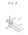
- a modified turnover unit 16a which comprises one front and back inverting roller 34 and a pair of turn bars 35a and 35b to invert continuous paper W from back to front while shifting its phase in a direction of its width by the length L.
- continuous paper W when traveling in both the first and second printing unit trains 10 and 11 can face its one face to the same side (without inverting front to back or vice versa) and can be printed on the same face.
- continuous paper W printed second (the last time) is shown discharged through the outlet guide roller 22d into the discharge section 7 after passing through the cooling roller unit 4, it may be discharged into the discharge section 7 without passing through the cooling roller unit since the continuous paper W printed second (the last time) need no longer be opposed to print heads.
Landscapes
- Ink Jet (AREA)
- Accessory Devices And Overall Control Thereof (AREA)
- Handling Of Continuous Sheets Of Paper (AREA)
- Glass Compositions (AREA)
- Noodles (AREA)
- Dot-Matrix Printers And Others (AREA)
- Printers Characterized By Their Purpose (AREA)
Applications Claiming Priority (1)
| Application Number | Priority Date | Filing Date | Title |
|---|---|---|---|
| JP2006017458A JP5285207B2 (ja) | 2006-01-26 | 2006-01-26 | 印字装置 |
Publications (2)
| Publication Number | Publication Date |
|---|---|
| EP1813432A1 true EP1813432A1 (de) | 2007-08-01 |
| EP1813432B1 EP1813432B1 (de) | 2010-04-28 |
Family
ID=37895884
Family Applications (1)
| Application Number | Title | Priority Date | Filing Date |
|---|---|---|---|
| EP07101065A Not-in-force EP1813432B1 (de) | 2006-01-26 | 2007-01-24 | Druckvorrichtung |
Country Status (6)
| Country | Link |
|---|---|
| US (1) | US7810921B2 (de) |
| EP (1) | EP1813432B1 (de) |
| JP (1) | JP5285207B2 (de) |
| AT (1) | ATE465886T1 (de) |
| DE (1) | DE602007006068D1 (de) |
| ES (1) | ES2343657T3 (de) |
Cited By (5)
| Publication number | Priority date | Publication date | Assignee | Title |
|---|---|---|---|---|
| EP2338816A3 (de) * | 2009-09-16 | 2011-09-28 | Xerox Corporation | Medieninversionssystem für einen kontinuierlichen Netzdrucker |
| CN104626747A (zh) * | 2013-11-12 | 2015-05-20 | 精工爱普生株式会社 | 打印机 |
| CN109878222A (zh) * | 2019-04-02 | 2019-06-14 | 广州益峰尖纸制品有限公司 | 一种pcb油墨固化装置及其工作方法 |
| WO2021018507A1 (en) * | 2019-07-26 | 2021-02-04 | Xeikon Manufacturing N.V. | Printing apparatus with uniform cooled roller |
| EP3885150A1 (de) * | 2020-03-23 | 2021-09-29 | SCREEN Holdings Co., Ltd. | Druckvorrichtung, drucksystem und druckverfahren |
Families Citing this family (26)
| Publication number | Priority date | Publication date | Assignee | Title |
|---|---|---|---|---|
| JP4485923B2 (ja) * | 2004-11-19 | 2010-06-23 | 大日本スクリーン製造株式会社 | 両面印刷装置 |
| JP5274977B2 (ja) * | 2008-10-24 | 2013-08-28 | 株式会社ミヤコシ | インクジェット記録装置 |
| JP5505592B2 (ja) * | 2009-01-29 | 2014-05-28 | セイコーエプソン株式会社 | 記録装置 |
| JP5339204B2 (ja) * | 2009-08-05 | 2013-11-13 | 株式会社リコー | 冷却装置及び画像形成装置 |
| JP5582392B2 (ja) * | 2009-08-26 | 2014-09-03 | 株式会社リコー | 冷却装置及び画像形成装置 |
| EP2295252B1 (de) * | 2009-08-27 | 2012-10-10 | Seiko Epson Corporation | Aufzeichnungsvorrichtung |
| JP2011046094A (ja) * | 2009-08-27 | 2011-03-10 | Seiko Epson Corp | 記録装置 |
| JP5260456B2 (ja) | 2009-09-24 | 2013-08-14 | 富士フイルム株式会社 | 画像記録装置 |
| US8231196B2 (en) * | 2010-02-12 | 2012-07-31 | Xerox Corporation | Continuous feed duplex printer |
| JP5772077B2 (ja) * | 2011-03-08 | 2015-09-02 | セイコーエプソン株式会社 | 記録装置及び記録方法 |
| JP5623674B2 (ja) * | 2011-06-01 | 2014-11-12 | ケーニツヒ ウント バウエル アクチエンゲゼルシヤフトKoenig & BauerAktiengesellschaft | 印刷機及びウェブ張力を調整する方法 |
| JP5921139B2 (ja) * | 2011-10-21 | 2016-05-24 | キヤノン株式会社 | プリント装置 |
| JP5945494B2 (ja) * | 2012-11-01 | 2016-07-05 | 日本写真印刷株式会社 | 熱転写装置及び熱転写方法 |
| JP6221259B2 (ja) | 2013-02-27 | 2017-11-01 | セイコーエプソン株式会社 | 液体吐出装置 |
| JP6347777B2 (ja) * | 2013-03-29 | 2018-06-27 | セーレン株式会社 | インクジェット記録装置 |
| JP5780266B2 (ja) * | 2013-06-26 | 2015-09-16 | 富士ゼロックス株式会社 | 画像形成装置及び粉体塗布装置 |
| JP5729452B2 (ja) * | 2013-11-14 | 2015-06-03 | セイコーエプソン株式会社 | 液体吐出装置 |
| JP2016179551A (ja) | 2015-03-23 | 2016-10-13 | 富士ゼロックス株式会社 | 画像形成ユニット、画像形成装置 |
| JP6668772B2 (ja) * | 2015-08-07 | 2020-03-18 | 富士ゼロックス株式会社 | 吐出装置、加湿装置 |
| JP6718390B2 (ja) * | 2017-02-01 | 2020-07-08 | 株式会社Screenホールディングス | 印刷装置 |
| ES2730122B2 (es) * | 2018-05-07 | 2020-03-12 | Latorre Jesus Francisco Barberan | Procedimiento para producir relieves mediante impresion digital y maquina de impresion digital |
| JP7061936B2 (ja) * | 2018-06-28 | 2022-05-02 | 株式会社Screenホールディングス | インクジェット印刷システム |
| JP7663330B2 (ja) * | 2020-09-18 | 2025-04-16 | 株式会社Screenホールディングス | 印刷装置 |
| WO2024024241A1 (ja) * | 2022-07-25 | 2024-02-01 | 富士フイルム株式会社 | 媒体処理装置及び液体付与システム |
| JP2024041403A (ja) * | 2022-09-14 | 2024-03-27 | 株式会社Screenホールディングス | 印刷装置 |
| IT202300025200A1 (it) * | 2023-11-27 | 2025-05-27 | Atlantic Zeiser Gmbh | Sistema e metodo di stampa |
Citations (5)
| Publication number | Priority date | Publication date | Assignee | Title |
|---|---|---|---|---|
| JPH01157860A (ja) | 1987-09-11 | 1989-06-21 | Canon Inc | インクジェット記録装置 |
| US20030081227A1 (en) * | 2001-10-30 | 2003-05-01 | Williams Kenneth R. | Multiple print unit configurations |
| JP2004224002A (ja) | 2003-01-27 | 2004-08-12 | Miyakoshi Printing Machinery Co Ltd | 表裏印字装置 |
| JP2004223765A (ja) * | 2003-01-20 | 2004-08-12 | Fuji Photo Film Co Ltd | サーマルプリンタ及びサーマルヘッド |
| EP1738916A1 (de) * | 2005-06-30 | 2007-01-03 | Eastman Kodak Company | Verfahren und Tintenstrahldruckvorrichtung zum Bedrucken und Trocknen eines Bedruckstoffes |
Family Cites Families (9)
| Publication number | Priority date | Publication date | Assignee | Title |
|---|---|---|---|---|
| USRE24948E (en) * | 1961-03-21 | zuckerman | ||
| US2680404A (en) * | 1949-12-09 | 1954-06-08 | Harris Seybold Co | Multiunit printing press |
| US3906855A (en) * | 1973-01-30 | 1975-09-23 | Wood Industries Inc | Web turning bar device |
| US5036600A (en) * | 1990-07-24 | 1991-08-06 | Harris Graphics Corporation | Chill roll assembly |
| IE65402B1 (en) * | 1991-07-30 | 1995-10-18 | Smurfit Web Research Limited | Improved printing process and apparatus |
| JPH0564877A (ja) * | 1991-09-10 | 1993-03-19 | Komori Corp | 輪転印刷機のウエブ加湿装置 |
| JP3570853B2 (ja) * | 1997-05-12 | 2004-09-29 | 株式会社リコー | 樹脂層形成装置及び該装置を備えた画像形成装置 |
| JP2002229276A (ja) * | 2000-11-30 | 2002-08-14 | Ricoh Co Ltd | 画像形成装置および方法ならびに画像形成システム |
| JP4552511B2 (ja) * | 2003-08-19 | 2010-09-29 | コニカミノルタビジネステクノロジーズ株式会社 | インクジェットプリンタ |
-
2006
- 2006-01-26 JP JP2006017458A patent/JP5285207B2/ja not_active Expired - Fee Related
-
2007
- 2007-01-23 US US11/656,066 patent/US7810921B2/en active Active
- 2007-01-24 AT AT07101065T patent/ATE465886T1/de active
- 2007-01-24 ES ES07101065T patent/ES2343657T3/es active Active
- 2007-01-24 DE DE602007006068T patent/DE602007006068D1/de active Active
- 2007-01-24 EP EP07101065A patent/EP1813432B1/de not_active Not-in-force
Patent Citations (5)
| Publication number | Priority date | Publication date | Assignee | Title |
|---|---|---|---|---|
| JPH01157860A (ja) | 1987-09-11 | 1989-06-21 | Canon Inc | インクジェット記録装置 |
| US20030081227A1 (en) * | 2001-10-30 | 2003-05-01 | Williams Kenneth R. | Multiple print unit configurations |
| JP2004223765A (ja) * | 2003-01-20 | 2004-08-12 | Fuji Photo Film Co Ltd | サーマルプリンタ及びサーマルヘッド |
| JP2004224002A (ja) | 2003-01-27 | 2004-08-12 | Miyakoshi Printing Machinery Co Ltd | 表裏印字装置 |
| EP1738916A1 (de) * | 2005-06-30 | 2007-01-03 | Eastman Kodak Company | Verfahren und Tintenstrahldruckvorrichtung zum Bedrucken und Trocknen eines Bedruckstoffes |
Cited By (12)
| Publication number | Priority date | Publication date | Assignee | Title |
|---|---|---|---|---|
| EP2338816A3 (de) * | 2009-09-16 | 2011-09-28 | Xerox Corporation | Medieninversionssystem für einen kontinuierlichen Netzdrucker |
| US8316766B2 (en) | 2009-09-16 | 2012-11-27 | Xerox Corporation | Media inversion system for a continuous web printer |
| US8646385B2 (en) | 2009-09-16 | 2014-02-11 | Xerox Corporation | Media inversion system for a continuous web printer |
| CN104626747A (zh) * | 2013-11-12 | 2015-05-20 | 精工爱普生株式会社 | 打印机 |
| CN109878222A (zh) * | 2019-04-02 | 2019-06-14 | 广州益峰尖纸制品有限公司 | 一种pcb油墨固化装置及其工作方法 |
| CN109878222B (zh) * | 2019-04-02 | 2020-11-17 | 毅嘉电子(苏州)有限公司 | 一种pcb油墨固化装置 |
| WO2021018507A1 (en) * | 2019-07-26 | 2021-02-04 | Xeikon Manufacturing N.V. | Printing apparatus with uniform cooled roller |
| NL2023575B1 (en) * | 2019-07-26 | 2021-02-18 | Xeikon Mfg Nv | Printing apparatus with improved cooling |
| US11878507B2 (en) | 2019-07-26 | 2024-01-23 | Xeikon Manufacturing N.V | Printing apparatus with uniform cooled roller |
| EP3885150A1 (de) * | 2020-03-23 | 2021-09-29 | SCREEN Holdings Co., Ltd. | Druckvorrichtung, drucksystem und druckverfahren |
| KR20210118732A (ko) * | 2020-03-23 | 2021-10-01 | 가부시키가이샤 스크린 홀딩스 | 인쇄 장치, 인쇄 시스템 및 인쇄 방법 |
| US11345174B2 (en) | 2020-03-23 | 2022-05-31 | SCREEN Holdings Co., Ltd. | Printing apparatus, printing system and printing method |
Also Published As
| Publication number | Publication date |
|---|---|
| ATE465886T1 (de) | 2010-05-15 |
| JP2007196513A (ja) | 2007-08-09 |
| US7810921B2 (en) | 2010-10-12 |
| JP5285207B2 (ja) | 2013-09-11 |
| ES2343657T3 (es) | 2010-08-05 |
| US20070172285A1 (en) | 2007-07-26 |
| EP1813432B1 (de) | 2010-04-28 |
| DE602007006068D1 (de) | 2010-06-10 |
Similar Documents
| Publication | Publication Date | Title |
|---|---|---|
| EP1813432B1 (de) | Druckvorrichtung | |
| US6659602B2 (en) | Ink-jet printer arrangement for printing both sides of a web | |
| US20180335258A1 (en) | Adjustable interlacing of drying rollers in a print system | |
| US8662656B2 (en) | Inkjet web printer and duplex web printing path | |
| JP6621995B2 (ja) | 冷却用ローラ及びそれを備えた印刷装置 | |
| US20090189929A1 (en) | Continuous paper web duplex inkjet printing unit | |
| US20130293649A1 (en) | Web inkjet printing method and apparatus using an air bar | |
| US6079330A (en) | Rotary press having a heating roller for drying | |
| EP3885150B1 (de) | Druckvorrichtung, drucksystem und druckverfahren | |
| KR20210118730A (ko) | 건조 장치, 인쇄 시스템 및 건조 방법 | |
| KR20210118731A (ko) | 건조 장치, 인쇄 시스템 및 건조 방법 | |
| CN110757965B (zh) | 干燥装置及具备该干燥装置的喷墨打印装置 | |
| JP4847089B2 (ja) | 幅広型シート用のシート処理装置 | |
| CN110834478B (zh) | 干燥装置及具备该干燥装置的喷墨打印装置 | |
| HK1103382A (en) | Printing apparatus | |
| JP2011161737A (ja) | ウェブ搬送装置及び印刷機 | |
| CN109311336B (zh) | 利用水分分布的打印方法及打印设备 | |
| JP4465156B2 (ja) | 表裏印字装置 | |
| JP3026558B2 (ja) | インクジェットプリントシステムにおけるインク温度安定化装置 | |
| EP1642735B1 (de) | Grossformatige Bogenhandhabungsvorrichtung | |
| JP7096543B2 (ja) | 印刷装置 | |
| JPH0325963Y2 (de) | ||
| JPH1120142A (ja) | ホットメルトインクジェットプリンタ | |
| JP2004142941A5 (de) |
Legal Events
| Date | Code | Title | Description |
|---|---|---|---|
| PUAI | Public reference made under article 153(3) epc to a published international application that has entered the european phase |
Free format text: ORIGINAL CODE: 0009012 |
|
| AK | Designated contracting states |
Kind code of ref document: A1 Designated state(s): AT BE BG CH CY CZ DE DK EE ES FI FR GB GR HU IE IS IT LI LT LU LV MC NL PL PT RO SE SI SK TR |
|
| AX | Request for extension of the european patent |
Extension state: AL BA HR MK YU |
|
| RIN1 | Information on inventor provided before grant (corrected) |
Inventor name: IZAWA, HIDEOC/O MIYAKOSHI PRINT.MACHINERY CO.LTD Inventor name: ISHIKAWA, AKIRAC/O MIYAKOSHI PRINT.MACHINERY CO.,L |
|
| 17P | Request for examination filed |
Effective date: 20070920 |
|
| REG | Reference to a national code |
Ref country code: HK Ref legal event code: DE Ref document number: 1103382 Country of ref document: HK |
|
| AKX | Designation fees paid |
Designated state(s): DE FR GB IT NL SE |
|
| RBV | Designated contracting states (corrected) |
Designated state(s): AT DE FR GB IT NL SE |
|
| RBV | Designated contracting states (corrected) |
Designated state(s): AT BE BG CH CY CZ DE DK EE ES FI FR GB GR HU IE IS IT LI LT LU LV MC NL PL PT RO SE SI SK TR |
|
| GRAP | Despatch of communication of intention to grant a patent |
Free format text: ORIGINAL CODE: EPIDOSNIGR1 |
|
| GRAS | Grant fee paid |
Free format text: ORIGINAL CODE: EPIDOSNIGR3 |
|
| GRAA | (expected) grant |
Free format text: ORIGINAL CODE: 0009210 |
|
| AK | Designated contracting states |
Kind code of ref document: B1 Designated state(s): AT BE BG CH CY CZ DE DK EE ES FI FR GB GR HU IE IS IT LI LT LU LV MC NL PL PT RO SE SI SK TR |
|
| REG | Reference to a national code |
Ref country code: GB Ref legal event code: FG4D |
|
| REG | Reference to a national code |
Ref country code: CH Ref legal event code: NV Representative=s name: E. BLUM & CO. AG PATENT- UND MARKENANWAELTE VSP Ref country code: CH Ref legal event code: EP |
|
| REG | Reference to a national code |
Ref country code: IE Ref legal event code: FG4D |
|
| REF | Corresponds to: |
Ref document number: 602007006068 Country of ref document: DE Date of ref document: 20100610 Kind code of ref document: P |
|
| REG | Reference to a national code |
Ref country code: DE Ref legal event code: R096 Ref document number: 602007006068 Country of ref document: DE Effective date: 20100610 |
|
| REG | Reference to a national code |
Ref country code: NL Ref legal event code: T3 |
|
| REG | Reference to a national code |
Ref country code: ES Ref legal event code: FG2A Ref document number: 2343657 Country of ref document: ES Kind code of ref document: T3 |
|
| REG | Reference to a national code |
Ref country code: SE Ref legal event code: TRGR |
|
| LTIE | Lt: invalidation of european patent or patent extension |
Effective date: 20100428 |
|
| PG25 | Lapsed in a contracting state [announced via postgrant information from national office to epo] |
Ref country code: LT Free format text: LAPSE BECAUSE OF FAILURE TO SUBMIT A TRANSLATION OF THE DESCRIPTION OR TO PAY THE FEE WITHIN THE PRESCRIBED TIME-LIMIT Effective date: 20100428 |
|
| PG25 | Lapsed in a contracting state [announced via postgrant information from national office to epo] |
Ref country code: SI Free format text: LAPSE BECAUSE OF FAILURE TO SUBMIT A TRANSLATION OF THE DESCRIPTION OR TO PAY THE FEE WITHIN THE PRESCRIBED TIME-LIMIT Effective date: 20100428 Ref country code: FI Free format text: LAPSE BECAUSE OF FAILURE TO SUBMIT A TRANSLATION OF THE DESCRIPTION OR TO PAY THE FEE WITHIN THE PRESCRIBED TIME-LIMIT Effective date: 20100428 Ref country code: LV Free format text: LAPSE BECAUSE OF FAILURE TO SUBMIT A TRANSLATION OF THE DESCRIPTION OR TO PAY THE FEE WITHIN THE PRESCRIBED TIME-LIMIT Effective date: 20100428 Ref country code: IS Free format text: LAPSE BECAUSE OF FAILURE TO SUBMIT A TRANSLATION OF THE DESCRIPTION OR TO PAY THE FEE WITHIN THE PRESCRIBED TIME-LIMIT Effective date: 20100828 |
|
| PG25 | Lapsed in a contracting state [announced via postgrant information from national office to epo] |
Ref country code: PL Free format text: LAPSE BECAUSE OF FAILURE TO SUBMIT A TRANSLATION OF THE DESCRIPTION OR TO PAY THE FEE WITHIN THE PRESCRIBED TIME-LIMIT Effective date: 20100428 Ref country code: CY Free format text: LAPSE BECAUSE OF FAILURE TO SUBMIT A TRANSLATION OF THE DESCRIPTION OR TO PAY THE FEE WITHIN THE PRESCRIBED TIME-LIMIT Effective date: 20100512 |
|
| PG25 | Lapsed in a contracting state [announced via postgrant information from national office to epo] |
Ref country code: GR Free format text: LAPSE BECAUSE OF FAILURE TO SUBMIT A TRANSLATION OF THE DESCRIPTION OR TO PAY THE FEE WITHIN THE PRESCRIBED TIME-LIMIT Effective date: 20100729 Ref country code: PT Free format text: LAPSE BECAUSE OF FAILURE TO SUBMIT A TRANSLATION OF THE DESCRIPTION OR TO PAY THE FEE WITHIN THE PRESCRIBED TIME-LIMIT Effective date: 20100830 Ref country code: DK Free format text: LAPSE BECAUSE OF FAILURE TO SUBMIT A TRANSLATION OF THE DESCRIPTION OR TO PAY THE FEE WITHIN THE PRESCRIBED TIME-LIMIT Effective date: 20100428 Ref country code: EE Free format text: LAPSE BECAUSE OF FAILURE TO SUBMIT A TRANSLATION OF THE DESCRIPTION OR TO PAY THE FEE WITHIN THE PRESCRIBED TIME-LIMIT Effective date: 20100428 |
|
| PG25 | Lapsed in a contracting state [announced via postgrant information from national office to epo] |
Ref country code: RO Free format text: LAPSE BECAUSE OF FAILURE TO SUBMIT A TRANSLATION OF THE DESCRIPTION OR TO PAY THE FEE WITHIN THE PRESCRIBED TIME-LIMIT Effective date: 20100428 Ref country code: CZ Free format text: LAPSE BECAUSE OF FAILURE TO SUBMIT A TRANSLATION OF THE DESCRIPTION OR TO PAY THE FEE WITHIN THE PRESCRIBED TIME-LIMIT Effective date: 20100428 Ref country code: SK Free format text: LAPSE BECAUSE OF FAILURE TO SUBMIT A TRANSLATION OF THE DESCRIPTION OR TO PAY THE FEE WITHIN THE PRESCRIBED TIME-LIMIT Effective date: 20100428 |
|
| PLBE | No opposition filed within time limit |
Free format text: ORIGINAL CODE: 0009261 |
|
| STAA | Information on the status of an ep patent application or granted ep patent |
Free format text: STATUS: NO OPPOSITION FILED WITHIN TIME LIMIT |
|
| 26N | No opposition filed |
Effective date: 20110131 |
|
| REG | Reference to a national code |
Ref country code: DE Ref legal event code: R097 Ref document number: 602007006068 Country of ref document: DE Effective date: 20110131 |
|
| PG25 | Lapsed in a contracting state [announced via postgrant information from national office to epo] |
Ref country code: MC Free format text: LAPSE BECAUSE OF NON-PAYMENT OF DUE FEES Effective date: 20110131 |
|
| REG | Reference to a national code |
Ref country code: IE Ref legal event code: MM4A |
|
| PG25 | Lapsed in a contracting state [announced via postgrant information from national office to epo] |
Ref country code: IE Free format text: LAPSE BECAUSE OF NON-PAYMENT OF DUE FEES Effective date: 20110124 |
|
| PG25 | Lapsed in a contracting state [announced via postgrant information from national office to epo] |
Ref country code: LU Free format text: LAPSE BECAUSE OF NON-PAYMENT OF DUE FEES Effective date: 20110124 |
|
| REG | Reference to a national code |
Ref country code: HK Ref legal event code: WD Ref document number: 1103382 Country of ref document: HK |
|
| PG25 | Lapsed in a contracting state [announced via postgrant information from national office to epo] |
Ref country code: BG Free format text: LAPSE BECAUSE OF FAILURE TO SUBMIT A TRANSLATION OF THE DESCRIPTION OR TO PAY THE FEE WITHIN THE PRESCRIBED TIME-LIMIT Effective date: 20100728 Ref country code: TR Free format text: LAPSE BECAUSE OF FAILURE TO SUBMIT A TRANSLATION OF THE DESCRIPTION OR TO PAY THE FEE WITHIN THE PRESCRIBED TIME-LIMIT Effective date: 20100428 |
|
| PG25 | Lapsed in a contracting state [announced via postgrant information from national office to epo] |
Ref country code: HU Free format text: LAPSE BECAUSE OF FAILURE TO SUBMIT A TRANSLATION OF THE DESCRIPTION OR TO PAY THE FEE WITHIN THE PRESCRIBED TIME-LIMIT Effective date: 20100428 |
|
| REG | Reference to a national code |
Ref country code: FR Ref legal event code: PLFP Year of fee payment: 10 |
|
| REG | Reference to a national code |
Ref country code: FR Ref legal event code: PLFP Year of fee payment: 11 |
|
| REG | Reference to a national code |
Ref country code: FR Ref legal event code: PLFP Year of fee payment: 12 |
|
| PGFP | Annual fee paid to national office [announced via postgrant information from national office to epo] |
Ref country code: CH Payment date: 20180125 Year of fee payment: 12 Ref country code: ES Payment date: 20180220 Year of fee payment: 12 |
|
| PGFP | Annual fee paid to national office [announced via postgrant information from national office to epo] |
Ref country code: BE Payment date: 20180124 Year of fee payment: 12 Ref country code: AT Payment date: 20180122 Year of fee payment: 12 Ref country code: SE Payment date: 20180125 Year of fee payment: 12 |
|
| REG | Reference to a national code |
Ref country code: CH Ref legal event code: PL |
|
| REG | Reference to a national code |
Ref country code: AT Ref legal event code: MM01 Ref document number: 465886 Country of ref document: AT Kind code of ref document: T Effective date: 20190124 |
|
| REG | Reference to a national code |
Ref country code: BE Ref legal event code: MM Effective date: 20190131 |
|
| PG25 | Lapsed in a contracting state [announced via postgrant information from national office to epo] |
Ref country code: SE Free format text: LAPSE BECAUSE OF NON-PAYMENT OF DUE FEES Effective date: 20190125 |
|
| PG25 | Lapsed in a contracting state [announced via postgrant information from national office to epo] |
Ref country code: BE Free format text: LAPSE BECAUSE OF NON-PAYMENT OF DUE FEES Effective date: 20190131 |
|
| PG25 | Lapsed in a contracting state [announced via postgrant information from national office to epo] |
Ref country code: LI Free format text: LAPSE BECAUSE OF NON-PAYMENT OF DUE FEES Effective date: 20190131 Ref country code: AT Free format text: LAPSE BECAUSE OF NON-PAYMENT OF DUE FEES Effective date: 20190124 Ref country code: CH Free format text: LAPSE BECAUSE OF NON-PAYMENT OF DUE FEES Effective date: 20190131 |
|
| REG | Reference to a national code |
Ref country code: ES Ref legal event code: FD2A Effective date: 20200310 |
|
| PG25 | Lapsed in a contracting state [announced via postgrant information from national office to epo] |
Ref country code: ES Free format text: LAPSE BECAUSE OF NON-PAYMENT OF DUE FEES Effective date: 20190125 |
|
| PGFP | Annual fee paid to national office [announced via postgrant information from national office to epo] |
Ref country code: NL Payment date: 20210120 Year of fee payment: 15 Ref country code: FR Payment date: 20210121 Year of fee payment: 15 Ref country code: IT Payment date: 20210121 Year of fee payment: 15 |
|
| PGFP | Annual fee paid to national office [announced via postgrant information from national office to epo] |
Ref country code: GB Payment date: 20210121 Year of fee payment: 15 |
|
| REG | Reference to a national code |
Ref country code: NL Ref legal event code: MM Effective date: 20220201 |
|
| GBPC | Gb: european patent ceased through non-payment of renewal fee |
Effective date: 20220124 |
|
| PG25 | Lapsed in a contracting state [announced via postgrant information from national office to epo] |
Ref country code: NL Free format text: LAPSE BECAUSE OF NON-PAYMENT OF DUE FEES Effective date: 20220201 Ref country code: GB Free format text: LAPSE BECAUSE OF NON-PAYMENT OF DUE FEES Effective date: 20220124 |
|
| PG25 | Lapsed in a contracting state [announced via postgrant information from national office to epo] |
Ref country code: FR Free format text: LAPSE BECAUSE OF NON-PAYMENT OF DUE FEES Effective date: 20220131 |
|
| PG25 | Lapsed in a contracting state [announced via postgrant information from national office to epo] |
Ref country code: IT Free format text: LAPSE BECAUSE OF NON-PAYMENT OF DUE FEES Effective date: 20220124 |
|
| P01 | Opt-out of the competence of the unified patent court (upc) registered |
Effective date: 20230517 |
|
| PGFP | Annual fee paid to national office [announced via postgrant information from national office to epo] |
Ref country code: DE Payment date: 20240119 Year of fee payment: 18 |
|
| REG | Reference to a national code |
Ref country code: DE Ref legal event code: R119 Ref document number: 602007006068 Country of ref document: DE |
|
| PG25 | Lapsed in a contracting state [announced via postgrant information from national office to epo] |
Ref country code: DE Free format text: LAPSE BECAUSE OF NON-PAYMENT OF DUE FEES Effective date: 20250801 |