EP1813468B1 - Sitze - Google Patents
Sitze Download PDFInfo
- Publication number
- EP1813468B1 EP1813468B1 EP07000677A EP07000677A EP1813468B1 EP 1813468 B1 EP1813468 B1 EP 1813468B1 EP 07000677 A EP07000677 A EP 07000677A EP 07000677 A EP07000677 A EP 07000677A EP 1813468 B1 EP1813468 B1 EP 1813468B1
- Authority
- EP
- European Patent Office
- Prior art keywords
- seat
- abutment
- channel
- mounting support
- arm
- Prior art date
- Legal status (The legal status is an assumption and is not a legal conclusion. Google has not performed a legal analysis and makes no representation as to the accuracy of the status listed.)
- Not-in-force
Links
- 238000010276 construction Methods 0.000 description 2
- 230000003014 reinforcing effect Effects 0.000 description 2
Images


Classifications
-
- B—PERFORMING OPERATIONS; TRANSPORTING
- B60—VEHICLES IN GENERAL
- B60N—SEATS SPECIALLY ADAPTED FOR VEHICLES; VEHICLE PASSENGER ACCOMMODATION NOT OTHERWISE PROVIDED FOR
- B60N2/00—Seats specially adapted for vehicles; Arrangement or mounting of seats in vehicles
- B60N2/24—Seats specially adapted for vehicles; Arrangement or mounting of seats in vehicles for particular purposes or particular vehicles
- B60N2/30—Non-dismountable or dismountable seats storable in a non-use position, e.g. foldable spare seats
- B60N2/3038—Cushion movements
- B60N2/3063—Cushion movements by composed movement
- B60N2/3065—Cushion movements by composed movement in a longitudinal-vertical plane
-
- B—PERFORMING OPERATIONS; TRANSPORTING
- B60—VEHICLES IN GENERAL
- B60N—SEATS SPECIALLY ADAPTED FOR VEHICLES; VEHICLE PASSENGER ACCOMMODATION NOT OTHERWISE PROVIDED FOR
- B60N2/00—Seats specially adapted for vehicles; Arrangement or mounting of seats in vehicles
- B60N2/24—Seats specially adapted for vehicles; Arrangement or mounting of seats in vehicles for particular purposes or particular vehicles
-
- B—PERFORMING OPERATIONS; TRANSPORTING
- B60—VEHICLES IN GENERAL
- B60N—SEATS SPECIALLY ADAPTED FOR VEHICLES; VEHICLE PASSENGER ACCOMMODATION NOT OTHERWISE PROVIDED FOR
- B60N2/00—Seats specially adapted for vehicles; Arrangement or mounting of seats in vehicles
- B60N2/24—Seats specially adapted for vehicles; Arrangement or mounting of seats in vehicles for particular purposes or particular vehicles
- B60N2/30—Non-dismountable or dismountable seats storable in a non-use position, e.g. foldable spare seats
- B60N2/3038—Cushion movements
- B60N2/3063—Cushion movements by composed movement
-
- B—PERFORMING OPERATIONS; TRANSPORTING
- B60—VEHICLES IN GENERAL
- B60N—SEATS SPECIALLY ADAPTED FOR VEHICLES; VEHICLE PASSENGER ACCOMMODATION NOT OTHERWISE PROVIDED FOR
- B60N2/00—Seats specially adapted for vehicles; Arrangement or mounting of seats in vehicles
- B60N2/24—Seats specially adapted for vehicles; Arrangement or mounting of seats in vehicles for particular purposes or particular vehicles
- B60N2/30—Non-dismountable or dismountable seats storable in a non-use position, e.g. foldable spare seats
- B60N2/3088—Non-dismountable or dismountable seats storable in a non-use position, e.g. foldable spare seats characterised by the mechanical link
- B60N2/3093—Non-dismountable or dismountable seats storable in a non-use position, e.g. foldable spare seats characterised by the mechanical link slides
-
- B—PERFORMING OPERATIONS; TRANSPORTING
- B60—VEHICLES IN GENERAL
- B60N—SEATS SPECIALLY ADAPTED FOR VEHICLES; VEHICLE PASSENGER ACCOMMODATION NOT OTHERWISE PROVIDED FOR
- B60N2/00—Seats specially adapted for vehicles; Arrangement or mounting of seats in vehicles
- B60N2/24—Seats specially adapted for vehicles; Arrangement or mounting of seats in vehicles for particular purposes or particular vehicles
- B60N2/38—Seats specially adapted for vehicles; Arrangement or mounting of seats in vehicles for particular purposes or particular vehicles specially constructed for use on tractors or like off-road vehicles
Definitions
- This invention relates to seats and in particular to folding passenger seats for use in vehicles such as agricultural tractors or combines.
- FR-808,127 discloses a folding seat corresponding to the preamble of claim 1 and which comprises a seat part which is pivotally and slidably mounted in a frame between a generally horizontal working position and a generally vertical stowed position.
- a folding passenger seat arrangement for use in a tractor, the seat arrangement comprising a mounting support for mounting on the inside of a fender of a rear wheel of a tractor and, a seat which is pivotally and slidably mounted on the support for movement between a generally horizontal working position and a lower generally vertical stowed position, characterised in that the mounting support is a single channel section with a track slot cut in two opposing sides of the channel, the seat including a seat pan and an arm projecting therefrom which includes, at a location remote from the pan, pivot means in the form of first pin means which projects from the arm and engages and slides along the slots in the channel as the seat pivots between its working and stowed positions, the arm also including first abutment means in the form of a second pin means which projects from the arm at a location intermediate the first pin means and the seat pan, the second pin means engaging the second abutment means in the form of upper notches formed in the sides of the channel adjacent the upper end of the channel
- the seat is mounted for pivoting about a generally horizontal axis on the mounting support by a pivot means, said pivot means also being slideable in a track in the support so that the seat can be pivoted and towered relative to the support as it moves from its working to its stowed position.
- the pivot means may be arranged to contact an upper end of the track in the mounting Support when the seat is in its working position with the seat being held generally horizontal by a first abutment on the seat, located between the pivot means and the seat, which contacts a second abutment on the mounting support so that any weight placed on the seat forces the pivot means against the upper end of the track.
- the mounting support includes a third abutment located below the second abutment which is contacted by the first abutment when the seat is moved to its stowed position.
- the weight of the seat forces the pivot means into contact with the lower end of the track and the first abutment into contact with the third abutment thus maintaining the seat safely stowed.
- the folding seat arrangement 10 comprises a seat 11 and a mounting support 12 which, as shown in Figures 1 and 2 , can conveniently be mounted on the inside of the fender 13 of the rear wheel of a tractor adjacent the cab door.
- the seat 11 comprises a seat pan 14 which comprises two half panels 14a welded on either side of a central tube 15 with reinforcing plates 16 sandwiched between the panels 14a and the tube 15 in cut outs 17.
- the seat pan is reinforced on its underside by ribs 18 again welded in position.
- the end portion 19 of tube 15 is bent slightly and together with the reinforcing plates 16 forms an arm 20 which projects from the rear of the seat pan.
- This arm 20 includes two pairs of aligned holes 21 and 22 which can receive cross-pins 23 and 24 respectively as will be described below.
- Pins 23 and 24 are spring roll pins which grip holes 21 and 22 when inserted.
- the seat pan is completed by an upholstered cushion 25a also a lower plastic skin 25b which is shown in Figures 1 and 2.
- Figure 2 shows an alternative seat pan construction in which the separate panels 14 and ribs 18 are replaced by a single seat pan 25b which has a raised stiffening edge flange 25c. This construction is better suited to high volume production.
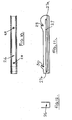
- the seat is mounted on a mounting support 26 shown in detail in Figures 10 to 12 which is generally of a channel shaped cross-section.
- Each side of the channel is provided with a track in the form of a slot 27. This track is arranged to be bolted to the inside of the rear fender 13 of the tractor cab by bolts extending through holes 28.
- Each side of the channel shaped support 26 is provided with an upper notch 29 and lower notch 30 whose operation will be described below.
- the seat is mounted on the support 26 by inserting the pin 23 through the slots 27 and through the aligned holes 21 in the arm 20 of the seat.
- the second pin 24 is inserted through the aligned holes 22 in the arm 20 and is engageable with upper notch 29 when the seat is in its generally horizontal working position and with the lower notch 30 when the seat is in its generally vertical stowed position.
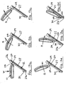
- Figures 13a to 13f show the seat in various position.
- the working position of the seat is shown in Figure 13a when the pin 24 is engaged in the upper notches 29 and the pivot pin 23 is adjacent the upper end 27a of the slots 27.
- any weight W applied to the seat tends to force the pivot 23 towards and into contact with the upper end 27a of the notches 27.
- the present invention thus provides a folding passenger seat which is particularly suitable for use in an agricultural tractor or combine and which, when mounted on the inner surface of the fender of the rear wheel and placed adjacent the entry door of the cab, occupies very little space when in the stowed position but offers a fully serviceable passenger seat when in the working position.
Landscapes
- Engineering & Computer Science (AREA)
- Aviation & Aerospace Engineering (AREA)
- Transportation (AREA)
- Mechanical Engineering (AREA)
- Seats For Vehicles (AREA)
- Body Structure For Vehicles (AREA)
Claims (4)
- Klappbare Sitzanordnung (10) für einen Benutzer oder Passagier zum Gebrauch in einem Zugfahrzeug, insbesondere Traktor, mit einer Anbauabstützung (12) zum Anbauen an die Innenseite eines Kotflügels (13) eines hinteren Rades eines Zugfahrzeugs und einem Sitz (11), der verschwenkbar und gleitend an der Anbauabstützung angebaut ist für eine Bewegung zwischen einer grundsätzlich horizontalen Arbeitsposition und einer niedrigeren grundsätzlich vertikalen Verstau-Position, dadurch gekennzeichnet, dass die Anbauabstützung (12) einen einzelnen Kanalabschnitt (26) aufweist mit Bahnschlitzen (27), die in zwei gegenüberliegende Seiten des Kanals geschnitten sind, wobei der Sitz eine Sitzpfanne (14) und einen hiervon abstehenden Arm (20) aufweist, der an einem Ort abseits der Pfanne Schwenkmittel aufweist in Form eines ersten Pin-artigen Organs (23), welches von dem Arm absteht und eingreift in die Schlitze oder in Wechselwirkung tritt mit den Schlitzen (27) in dem Kanal und entlang der Schlitze (27) gleitet mit Verschwenkung des Sitzes zwischen der Arbeitsposition und der Verstau-Position, und der Arm (20) auch mindestens ein erstes Anschlagorgan in Form eines zweiten Pin-artigen Organs (24) aufweist, welches von dem Arm absteht an einem Ort zwischen dem ersten Pin-artigen Organ und der Sitzpfanne, und das zweite Pin-artige Organ (24) eingreift in mindestens ein zweites Anschlagorgan oder in Wechselwirkung tritt mit mindestens einem zweiten Anschlagorgan in Form oberer Einbuchtungen oder Nuten (29), die in den Seiten des Kanals (26) benachbart dem oberen Ende des Kanals gebildet sind, wenn sich der Sitz in seiner Arbeitsposition befindet, und eingreifen in mindestens ein drittes Anschlagorgan oder in Wechselwirkung treten mit mindestens einem dritten Anschlagorgan in Form unterer Einbuchtungen oder Nuten (30), die in den Seiten des Kanals (26) benachbart dem unteren Ende des Kanals gebildet sind, wenn sich der Sitz in seiner Verstau-Position befindet.
- Sitzanordnung nach Anspruch 1, dadurch gekennzeichnet, dass das Schwenkmittel (23) ein oberes Ende (27a) der Bahn (27) in der Anbauabstützung kontaktiert, wenn sich der Sitz in seiner Arbeitsposition befindet, wobei der Sitz durch das erste Anschlagorgan (24) an dem Sitz, welches zwischen dem Schwenkmittel und dem Sitz angeordnet ist und ein zweites Anschlagorgan (29) auf oder an der Anbauabstützung (12) kontaktiert, grundsätzlich horizontal gehalten wird, so dass sämtliches Gewicht, welches auf dem Sitz angeordnet ist, das Schwenkmittel (23) gegen das obere Ende (27a) der Bahn beaufschlagt.
- Sitzanordnung nach Anspruch 2, dadurch gekennzeichnet, dass die Anbauabstützung (12) ein drittes Anschlagorgan (30) aufweist, welches unter dem zweiten Anschlagorgan (29) angeordnet ist und von dem ersten Abstützorgan (24) kontaktiert wird, wenn der Sitz (11) in die Verstau-Position bewegt ist.
- Sitzanordnung nach Anspruch 3, dadurch gekennzeichnet, dass, wenn sich der Sitz (11) in der Verstau-Position befindet, das Gewicht des Sitzes das Schwenkmittel (23) in Kontakt mit einem unteren Ende (27b) der Bahn (27) und das erste Anschlagorgan (24) in Kontakt mit dem dritten Anschlagorgan (30) beaufschlagt, wodurch der Sitz sicher verstaut gehalten wird.
Applications Claiming Priority (1)
| Application Number | Priority Date | Filing Date | Title |
|---|---|---|---|
| GB0601741A GB2434527B (en) | 2006-01-28 | 2006-01-28 | Folding vehicle passenger seat |
Publications (2)
| Publication Number | Publication Date |
|---|---|
| EP1813468A1 EP1813468A1 (de) | 2007-08-01 |
| EP1813468B1 true EP1813468B1 (de) | 2011-03-23 |
Family
ID=36061046
Family Applications (1)
| Application Number | Title | Priority Date | Filing Date |
|---|---|---|---|
| EP07000677A Not-in-force EP1813468B1 (de) | 2006-01-28 | 2007-01-15 | Sitze |
Country Status (3)
| Country | Link |
|---|---|
| EP (1) | EP1813468B1 (de) |
| DE (1) | DE602007013302D1 (de) |
| GB (1) | GB2434527B (de) |
Families Citing this family (1)
| Publication number | Priority date | Publication date | Assignee | Title |
|---|---|---|---|---|
| ITMI20072164A1 (it) | 2007-11-14 | 2009-05-15 | Same Deutz Fahr Group Spa | Sedile pieghevole per il passeggero di un veicolo |
Family Cites Families (12)
| Publication number | Priority date | Publication date | Assignee | Title |
|---|---|---|---|---|
| GB191226906A (en) * | 1911-12-20 | 1913-08-07 | Fernand Henri Labourdette | Improvements in Folding Seats with Backs for Automobiles and similar Vehicles. |
| US1685137A (en) * | 1927-02-10 | 1928-09-25 | American Car & Foundry Co | Foldable seat |
| US1712704A (en) * | 1927-05-25 | 1929-05-14 | Addison S Kiser | Wall seat |
| GB328148A (en) * | 1929-06-04 | 1930-04-24 | Widney Mfg Company Ltd | Improvements relating to adjustable seats |
| US1826643A (en) * | 1930-02-01 | 1931-10-06 | Gustin Bacon Mfg Co | Folding adjustable locomotive cab seat |
| FR808127A (fr) * | 1936-07-16 | 1937-01-29 | Dispositif pouvant être utilisé comme tablette ou siège pliant | |
| DE2227659C3 (de) * | 1972-06-07 | 1979-11-22 | Paul Erich 6360 Friedberg Kettler | In eine Nichtgebrauchslage bringbarer Beifahrersitz für Schlepper, Traktoren oder Baufahrzeuge |
| FR2460226A1 (fr) * | 1979-07-04 | 1981-01-23 | Renault | Dispositif de reglage longitudinal d'un siege pliant de vehicule automobile |
| US5374106A (en) * | 1993-09-30 | 1994-12-20 | Agco Corporation | Folding auxiliary seat for tractor cab |
| AUPO678897A0 (en) * | 1997-05-14 | 1997-06-05 | Jpm Industries Pty Ltd | Foldable chair |
| US5868469A (en) * | 1998-03-30 | 1999-02-09 | Ming; Liao Tsung | Folding chair having a seat adjustable in height |
| JP2001000267A (ja) * | 1999-06-23 | 2001-01-09 | Seiko Kogyo Kk | 高さ調節椅子の座部の支持構造 |
-
2006
- 2006-01-28 GB GB0601741A patent/GB2434527B/en not_active Expired - Lifetime
-
2007
- 2007-01-15 EP EP07000677A patent/EP1813468B1/de not_active Not-in-force
- 2007-01-15 DE DE602007013302T patent/DE602007013302D1/de active Active
Also Published As
| Publication number | Publication date |
|---|---|
| DE602007013302D1 (de) | 2011-05-05 |
| GB0601741D0 (en) | 2006-03-08 |
| GB2434527A (en) | 2007-08-01 |
| EP1813468A1 (de) | 2007-08-01 |
| GB2434527B (en) | 2009-08-19 |
Similar Documents
| Publication | Publication Date | Title |
|---|---|---|
| EP1888367B1 (de) | Umwandelbarer monogestellsitz | |
| EP2269862B1 (de) | Fahrzeugsitzanordnung und Fahrzeuge damit | |
| EP1646528B1 (de) | Verstellbare seitenpolster | |
| US6070934A (en) | Folding seat mounting apparatus | |
| US8136857B2 (en) | Pick-up style utility vehicle with expandable cargo bed | |
| US9227530B2 (en) | Vehicle seat | |
| WO2012138472A2 (en) | Seat assembly having a front cushion module | |
| US20120204771A1 (en) | Folding table | |
| US9039060B1 (en) | Utility vehicle | |
| US20150048603A1 (en) | Vehicular slide rail device | |
| CN103909846A (zh) | 多用途车辆 | |
| EP1518745A2 (de) | Sitzstruktur für ein Fahrzeug und Fahrzeug versehen mit dergleichen | |
| EP2855196B1 (de) | Klapp- und kniesitz mit rückwärtiger klappbewegung | |
| EP1813468B1 (de) | Sitze | |
| US8066325B2 (en) | Deployable bolster for a vehicle seat | |
| US20050242647A1 (en) | Device for reclining seatback of vehicle | |
| JP7239802B2 (ja) | シートクッションフレーム構造 | |
| US20210354603A1 (en) | Conveyance seat | |
| EP1808330B1 (de) | Sitz für Kraftfahrzeug, der entlang einer ersten Achse x und einer zweiten Achse y beweglich ist, und Kraftfahrzeug, das einen solchen Sitz umfasst | |
| JP4494171B2 (ja) | 助手席シートの位置調節装置 | |
| US8079564B2 (en) | Mechanism for locking the rails of a motor vehicle seat | |
| US20070108811A1 (en) | Seat for a motor vehicle, and motor vehicle equipped with this seat | |
| JPH10226254A (ja) | 車両用シート装置 | |
| EP1723000B1 (de) | Befestigungsanordnung für einen fahrzeugsitz | |
| JP4013871B2 (ja) | 車両用のシート構造 |
Legal Events
| Date | Code | Title | Description |
|---|---|---|---|
| PUAI | Public reference made under article 153(3) epc to a published international application that has entered the european phase |
Free format text: ORIGINAL CODE: 0009012 |
|
| AK | Designated contracting states |
Kind code of ref document: A1 Designated state(s): AT BE BG CH CY CZ DE DK EE ES FI FR GB GR HU IE IS IT LI LT LU LV MC NL PL PT RO SE SI SK TR |
|
| AX | Request for extension of the european patent |
Extension state: AL BA HR MK YU |
|
| 17P | Request for examination filed |
Effective date: 20080201 |
|
| AKX | Designation fees paid |
Designated state(s): DE FR GB IT |
|
| 17Q | First examination report despatched |
Effective date: 20080410 |
|
| GRAP | Despatch of communication of intention to grant a patent |
Free format text: ORIGINAL CODE: EPIDOSNIGR1 |
|
| GRAS | Grant fee paid |
Free format text: ORIGINAL CODE: EPIDOSNIGR3 |
|
| GRAA | (expected) grant |
Free format text: ORIGINAL CODE: 0009210 |
|
| AK | Designated contracting states |
Kind code of ref document: B1 Designated state(s): DE FR GB IT |
|
| REG | Reference to a national code |
Ref country code: GB Ref legal event code: FG4D |
|
| REF | Corresponds to: |
Ref document number: 602007013302 Country of ref document: DE Date of ref document: 20110505 Kind code of ref document: P |
|
| REG | Reference to a national code |
Ref country code: DE Ref legal event code: R096 Ref document number: 602007013302 Country of ref document: DE Effective date: 20110505 |
|
| PLBE | No opposition filed within time limit |
Free format text: ORIGINAL CODE: 0009261 |
|
| STAA | Information on the status of an ep patent application or granted ep patent |
Free format text: STATUS: NO OPPOSITION FILED WITHIN TIME LIMIT |
|
| 26N | No opposition filed |
Effective date: 20111227 |
|
| REG | Reference to a national code |
Ref country code: DE Ref legal event code: R097 Ref document number: 602007013302 Country of ref document: DE Effective date: 20111227 |
|
| REG | Reference to a national code |
Ref country code: FR Ref legal event code: PLFP Year of fee payment: 9 |
|
| PGFP | Annual fee paid to national office [announced via postgrant information from national office to epo] |
Ref country code: IT Payment date: 20150127 Year of fee payment: 9 Ref country code: DE Payment date: 20150121 Year of fee payment: 9 |
|
| PGFP | Annual fee paid to national office [announced via postgrant information from national office to epo] |
Ref country code: FR Payment date: 20150122 Year of fee payment: 9 Ref country code: GB Payment date: 20150121 Year of fee payment: 9 |
|
| REG | Reference to a national code |
Ref country code: DE Ref legal event code: R119 Ref document number: 602007013302 Country of ref document: DE |
|
| GBPC | Gb: european patent ceased through non-payment of renewal fee |
Effective date: 20160115 |
|
| REG | Reference to a national code |
Ref country code: FR Ref legal event code: ST Effective date: 20160930 |
|
| PG25 | Lapsed in a contracting state [announced via postgrant information from national office to epo] |
Ref country code: DE Free format text: LAPSE BECAUSE OF NON-PAYMENT OF DUE FEES Effective date: 20160802 Ref country code: GB Free format text: LAPSE BECAUSE OF NON-PAYMENT OF DUE FEES Effective date: 20160115 |
|
| PG25 | Lapsed in a contracting state [announced via postgrant information from national office to epo] |
Ref country code: FR Free format text: LAPSE BECAUSE OF NON-PAYMENT OF DUE FEES Effective date: 20160201 |
|
| PG25 | Lapsed in a contracting state [announced via postgrant information from national office to epo] |
Ref country code: IT Free format text: LAPSE BECAUSE OF NON-PAYMENT OF DUE FEES Effective date: 20160115 |