EP1813530A1 - Vorrichtung zum Formen einer Verpackung - Google Patents
Vorrichtung zum Formen einer Verpackung Download PDFInfo
- Publication number
- EP1813530A1 EP1813530A1 EP06101120A EP06101120A EP1813530A1 EP 1813530 A1 EP1813530 A1 EP 1813530A1 EP 06101120 A EP06101120 A EP 06101120A EP 06101120 A EP06101120 A EP 06101120A EP 1813530 A1 EP1813530 A1 EP 1813530A1
- Authority
- EP
- European Patent Office
- Prior art keywords
- inner part
- fill tube
- packaging
- former set
- outer layer
- Prior art date
- Legal status (The legal status is an assumption and is not a legal conclusion. Google has not performed a legal analysis and makes no representation as to the accuracy of the status listed.)
- Withdrawn
Links
- 238000004806 packaging method and process Methods 0.000 title claims abstract description 29
- 239000000463 material Substances 0.000 claims abstract description 55
- 230000001603 reducing effect Effects 0.000 claims abstract description 23
- 235000013305 food Nutrition 0.000 claims abstract description 14
- 238000000034 method Methods 0.000 claims description 19
- 238000011010 flushing procedure Methods 0.000 claims description 12
- 238000000576 coating method Methods 0.000 claims description 10
- 239000011248 coating agent Substances 0.000 claims description 8
- 239000011859 microparticle Substances 0.000 claims description 8
- 239000000725 suspension Substances 0.000 claims description 8
- WFKWXMTUELFFGS-UHFFFAOYSA-N tungsten Chemical compound [W] WFKWXMTUELFFGS-UHFFFAOYSA-N 0.000 claims description 8
- 239000004952 Polyamide Substances 0.000 claims description 7
- 229920002647 polyamide Polymers 0.000 claims description 7
- BWGNESOTFCXPMA-UHFFFAOYSA-N Dihydrogen disulfide Chemical compound SS BWGNESOTFCXPMA-UHFFFAOYSA-N 0.000 claims description 6
- 238000002844 melting Methods 0.000 claims description 6
- 230000008018 melting Effects 0.000 claims description 6
- 239000005022 packaging material Substances 0.000 claims description 6
- 239000002033 PVDF binder Substances 0.000 claims description 5
- 229920002981 polyvinylidene fluoride Polymers 0.000 claims description 5
- 238000004519 manufacturing process Methods 0.000 claims description 4
- 230000003746 surface roughness Effects 0.000 claims description 4
- 238000010438 heat treatment Methods 0.000 claims description 2
- 230000002093 peripheral effect Effects 0.000 claims description 2
- 229920006020 amorphous polyamide Polymers 0.000 claims 1
- 238000005299 abrasion Methods 0.000 abstract description 2
- 239000007789 gas Substances 0.000 description 21
- 230000000694 effects Effects 0.000 description 5
- IJGRMHOSHXDMSA-UHFFFAOYSA-N Atomic nitrogen Chemical compound N#N IJGRMHOSHXDMSA-UHFFFAOYSA-N 0.000 description 4
- 229910052782 aluminium Inorganic materials 0.000 description 4
- XAGFODPZIPBFFR-UHFFFAOYSA-N aluminium Chemical compound [Al] XAGFODPZIPBFFR-UHFFFAOYSA-N 0.000 description 4
- 238000004140 cleaning Methods 0.000 description 4
- 229910052751 metal Inorganic materials 0.000 description 4
- 239000002184 metal Substances 0.000 description 4
- 238000000465 moulding Methods 0.000 description 4
- 239000010935 stainless steel Substances 0.000 description 4
- 229910001220 stainless steel Inorganic materials 0.000 description 4
- 229910000831 Steel Inorganic materials 0.000 description 3
- 239000004411 aluminium Substances 0.000 description 3
- 229920001343 polytetrafluoroethylene Polymers 0.000 description 3
- 239000004810 polytetrafluoroethylene Substances 0.000 description 3
- 230000003068 static effect Effects 0.000 description 3
- 239000010959 steel Substances 0.000 description 3
- 239000004593 Epoxy Substances 0.000 description 2
- UCKMPCXJQFINFW-UHFFFAOYSA-N Sulphide Chemical compound [S-2] UCKMPCXJQFINFW-UHFFFAOYSA-N 0.000 description 2
- 230000033228 biological regulation Effects 0.000 description 2
- 239000000919 ceramic Substances 0.000 description 2
- 238000010276 construction Methods 0.000 description 2
- 238000005260 corrosion Methods 0.000 description 2
- 230000007797 corrosion Effects 0.000 description 2
- 239000003599 detergent Substances 0.000 description 2
- 239000000835 fiber Substances 0.000 description 2
- 235000013611 frozen food Nutrition 0.000 description 2
- 239000011521 glass Substances 0.000 description 2
- 238000003754 machining Methods 0.000 description 2
- 239000004005 microsphere Substances 0.000 description 2
- 238000012986 modification Methods 0.000 description 2
- 230000004048 modification Effects 0.000 description 2
- 229910052757 nitrogen Inorganic materials 0.000 description 2
- 239000004033 plastic Substances 0.000 description 2
- 229920003023 plastic Polymers 0.000 description 2
- 238000007789 sealing Methods 0.000 description 2
- 239000010703 silicon Substances 0.000 description 2
- 229910052710 silicon Inorganic materials 0.000 description 2
- 239000007921 spray Substances 0.000 description 2
- CWYNVVGOOAEACU-UHFFFAOYSA-N Fe2+ Chemical compound [Fe+2] CWYNVVGOOAEACU-UHFFFAOYSA-N 0.000 description 1
- 230000002411 adverse Effects 0.000 description 1
- 229910045601 alloy Inorganic materials 0.000 description 1
- 239000000956 alloy Substances 0.000 description 1
- 230000003385 bacteriostatic effect Effects 0.000 description 1
- 239000002775 capsule Substances 0.000 description 1
- 239000012459 cleaning agent Substances 0.000 description 1
- 238000011109 contamination Methods 0.000 description 1
- 238000001816 cooling Methods 0.000 description 1
- 239000000428 dust Substances 0.000 description 1
- 210000003414 extremity Anatomy 0.000 description 1
- 230000002209 hydrophobic effect Effects 0.000 description 1
- 230000000670 limiting effect Effects 0.000 description 1
- 230000007774 longterm Effects 0.000 description 1
- 210000003141 lower extremity Anatomy 0.000 description 1
- 238000012423 maintenance Methods 0.000 description 1
- 230000014759 maintenance of location Effects 0.000 description 1
- 239000007769 metal material Substances 0.000 description 1
- 230000036961 partial effect Effects 0.000 description 1
- 230000000737 periodic effect Effects 0.000 description 1
- -1 polytetrafluoroethylene Polymers 0.000 description 1
- 230000002829 reductive effect Effects 0.000 description 1
- 230000000717 retained effect Effects 0.000 description 1
- 235000019592 roughness Nutrition 0.000 description 1
- 238000000926 separation method Methods 0.000 description 1
- 230000035939 shock Effects 0.000 description 1
- 238000005245 sintering Methods 0.000 description 1
Images


Classifications
-
- B—PERFORMING OPERATIONS; TRANSPORTING
- B65—CONVEYING; PACKING; STORING; HANDLING THIN OR FILAMENTARY MATERIAL
- B65B—MACHINES, APPARATUS OR DEVICES FOR, OR METHODS OF, PACKAGING ARTICLES OR MATERIALS; UNPACKING
- B65B65/00—Details peculiar to packaging machines and not otherwise provided for; Arrangements of such details
- B65B65/06—Details peculiar to packaging machines and not otherwise provided for; Arrangements of such details coated or treated with anti-friction or anti-sticking materials, e.g. polytetrafluoroethylene
-
- B—PERFORMING OPERATIONS; TRANSPORTING
- B65—CONVEYING; PACKING; STORING; HANDLING THIN OR FILAMENTARY MATERIAL
- B65B—MACHINES, APPARATUS OR DEVICES FOR, OR METHODS OF, PACKAGING ARTICLES OR MATERIALS; UNPACKING
- B65B39/00—Nozzles, funnels or guides for introducing articles or materials into containers or wrappers
- B65B39/007—Guides or funnels for introducing articles into containers or wrappers
-
- B—PERFORMING OPERATIONS; TRANSPORTING
- B65—CONVEYING; PACKING; STORING; HANDLING THIN OR FILAMENTARY MATERIAL
- B65B—MACHINES, APPARATUS OR DEVICES FOR, OR METHODS OF, PACKAGING ARTICLES OR MATERIALS; UNPACKING
- B65B39/00—Nozzles, funnels or guides for introducing articles or materials into containers or wrappers
- B65B39/04—Nozzles, funnels or guides for introducing articles or materials into containers or wrappers having air-escape, or air-withdrawal, passages
-
- B—PERFORMING OPERATIONS; TRANSPORTING
- B65—CONVEYING; PACKING; STORING; HANDLING THIN OR FILAMENTARY MATERIAL
- B65B—MACHINES, APPARATUS OR DEVICES FOR, OR METHODS OF, PACKAGING ARTICLES OR MATERIALS; UNPACKING
- B65B9/00—Enclosing successive articles, or quantities of material, e.g. liquids or semiliquids, in flat, folded, or tubular webs of flexible sheet material; Subdividing filled flexible tubes to form packages
- B65B9/10—Enclosing successive articles, or quantities of material, in preformed tubular webs, or in webs formed into tubes around filling nozzles, e.g. extruded tubular webs
- B65B9/20—Enclosing successive articles, or quantities of material, in preformed tubular webs, or in webs formed into tubes around filling nozzles, e.g. extruded tubular webs the webs being formed into tubes in situ around the filling nozzles
- B65B9/22—Forming shoulders; Tube formers
Definitions
- the present invention relates to fill tubes of the type used for packaging purposes, in particular to former sets for use in vertical form, fill and seal machines.
- Packaging machines are known in which a product, such as a foodstuff, is sealed within one or more webs of polymeric material to form a package.
- Such packages may take different forms such as bags, sachets, tubes, envelopes, boxes, capsules and the like.
- the package may be evacuated or may be provided with a particular gas filling to preserve freshness.
- One manner of making such packages is to use a former set.
- the former set comprises a forming collar, which guides the web into a tubular shape around a fill tube. On the fill tube, a longitudinal seal is applied to form a closed tubular web.
- the tubular web is continuously withdrawn from one end of the fill tube as portions of product are fed into the other end of the fill tube.
- the filled tubular web leaving the lower end of the fill tube is sealed and severed, usually by an appropriate heat seal bar, to form individual packages.
- the fill tube and forming collar are supported by a suspension frame.
- Prior art former sets have generally used stainless steel fill tubes.
- Food standard regulations impose strict limitations on the materials that may come into contact with foodstuffs. Furthermore, depending on the product being packaged, the interior of the fill tube is exposed to considerable wear. Frozen foods are particularly abrasive in this respect.
- the suspension frame and forming collar have also generally been made of steel in order to comply with food regulations and in order to ensure sufficient strength. Steel is also desirable for the purpose of cleaning. Certain food standards require the use of particularly effective cleaning agents that are highly corrosive. It is however a considerable disadvantage of steel that the whole construction is extremely heavy.
- Aluminium fill tubes are lightweight but are subject to corrosion by cleaning detergents. Furthermore, when used for wet products, the interior of the tube can be eroded by cathodic sacrifice due to electrolytic effects.
- Forming collars have been made of non-metallic materials such as fibre reinforced epoxy but this is not suitable for the fill tube itself.
- a particular problem with the use of plastics materials in this context is the presence of static electrical charge. Due to the constant movement of the packaging web over the forming collar and fill tube, static charge can build up. This is undesirable as it can cause powdery products and dust to be retained.
- Another requirement of the exterior surface of the fill tube and forming collar is that of low friction. Many plastic surfaces offer relatively high frictional resistance to polymeric packaging materials.
- An additional problem is apparent in the case that the fill tube or packaging web is wet. In this case, surface tension effects can cause the packaging web to adhere to the outside of the fill tube, preventing smooth processing.
- a packaging former set having a fill tube comprising an elongate tubular body having an upper end, a lower end and a bore, the body comprising an inner part and an outer part or layer, the inner part being formed of a first, relatively hard material, the outer part being formed of a second, polymeric material having a friction reducing outer surface.
- the inner and outer parts are intimately connected together preferably around their entire periphery.
- each material can be optimized to meet the requirements of the environment to which the part is exposed.
- the inner layer may be chosen to have the requisite hardness for withstanding abrasion by the products being packaged and should also meet the relevant food standard quality.
- the materials of both inner and outer parts are preferably of food standard quality, meaning that they are authorized for entering into contact with food products.
- the outer part may be chosen for its ability to provide a friction reducing outer surface, either directly or indirectly by its ability to be coated with other materials. By reducing friction, static effects may also be reduced. In general, it will also be of food standard quality. Both materials will preferably be chosen for their resistance to corrosion or damage, in particular by exposure to the product being packaged and to detergents of the type employed for cleaning.
- the inner part is provided with a peripheral groove on an outer surface adjacent to at least its lower end and the outer part terminates at and is engaged in the groove.
- the fill tube must be extremely resistant to damage that may typically occur during use and cleaning.
- the edges of the outer part must not be exposed to shock which could cause them to be raised and subject to further damage or become susceptible to contamination. By recessing the edge of the outer part in a groove in the inner part, such exposure is largely precluded. While the use of a groove of a limited axial extent is preferred, it is noted that the outer part may be embedded into the inner part over substantially the whole surface should this be desired.
- the outer surface of the outer part comprises a pattern or relief. It has been found that surface roughnesses of between 10 and 200 microns are ideal, depending upon the packaging materials used. Preferably a value of around 100 microns is favoured.
- One preferred manner of achieving such roughness is by including micro particles or microspheres in the material of the outer part.
- the micro particles may be any suitable inert material such as silicon, ceramics, glass or metal.
- the friction reducing outer surface may comprise a friction reducing material such as polytetrafluoroethylene (PTFE) or wolfram disulfide.
- the combination of a friction reducing material over an outer part having a surface relief produces an enhanced effect allowing ease of transport of the packaging web material over the fill tube.
- the friction reducing material may be applied both to the outer part and also to any other exposed surfaces such as edge regions of the inner part.
- the outer surface should be generally hydrophobic in order to reduce surface tension effects that could cause the packaging material to stick.
- Wolfram disulfide and friction reducing materials that may be applied at temperatures below the melting temperature of the outer part have been found highly effective in this context.
- the outer part has a thickness of between 0.2 mm and 2 mm, most preferably about 0.5 mm.
- such material thicknesses for the outer part are sufficient to achieve the desired effects while being sufficiently stable to mechanical stresses and easy to apply using coating techniques. It is however also understood that greater thicknesses could be used e.g. using coextrusion techniques to form the inner and outer parts.
- a longitudinal groove is formed in or through the outer part over substantially a lower half of its length.
- a removable seal plate may be embedded into the fill tube. The seal plate acts to provide counter pressure for the longitudinal seal assembly of a vertical fill/seal machine. Since this part is exposed to wear, its periodic replacement is desirable.
- a gas flushing channel is provided leading from a gas inlet nozzle situated towards the upper end of the body to a gas outlet adjacent the lower end of the body.
- the gas flushing channel may be used for packaging products under a particular atmosphere. Air may thereby be evacuated from the package prior to sealing and replaced or supplemented by e.g. nitrogen or another suitably inert or bacteriostatic gas.
- the bore of the fill tube should be "smooth".
- the gas flushing channel may preferably be recessed e.g. into a wall of the inner part.
- the bore is located eccentrically with respect to the inner part such that the wall has a varying thickness
- the gas flushing channel may then be formed within a thickened section of the wall.
- the gas flush channel is formed as a groove in the outer surface of the inner part that can be subsequently covered e.g. by the seal plate.
- the inner part may comprise any suitable food quality material of adequate hardness and durability.
- exemplary materials include stainless steel, aluminium and their alloys.
- the inner part comprises polyvinylidene fluoride (PVDF).
- PVDF polyvinylidene fluoride
- a particular advantage of this material is its ease of manufacture as it can be readily machined to form the above-mentioned circumferential groove and gas flush channel. It also has short term resistance to heat up to temperatures of 270 °C and long term resistance up to around 180-190 °C. This is useful in allowing the outer part to be bonded thereto without adversely affecting the structure of the inner part.
- the outer part comprises a mouldable polymeric material, preferably having a melting point of less than 200 °C.
- Polyamide has been found most suitable for this purpose and has shown itself to be exemplary in forming a good bond with the underlying inner part.
- the combination of polyamide and PVDF has been found exceptionally effective.
- polymeric coatings have been used for providing non-stick coatings to objects.
- Such non-stick polymeric materials of which PTFE is exemplary, characteristically have high melting points and require coating at temperatures above 400 °C using sintering techniques. Such materials are not suitable for application using moulding or spray moulding techniques.
- a packaging former set comprising a fill tube as described above together with a forming collar surrounding and spaced from the fill tube for guiding a generally flat web of packaging material into concentric engagement with the fill tube.
- the packaging former set may further comprise a suspension frame for supporting the fill tube and forming collar within a packaging machine and for maintaining the desired spacing.
- both the suspension frame and the forming collar substantially comprise polymeric materials.
- the former set has the advantage of considerably lower weight compared to existing metal former sets.
- substantially comprise polymeric materials is intended to mean that the main structural components are polymeric. It is understood that minor components and fixation elements such as bolts or the like may nevertheless be formed of metal.
- the packaging former set may further comprise an attachment, preferably a bayonet mount, by which further accessories such as a bag spreader or converter box, mounted on a mounting ring may be attached to the fill tube.
- an attachment preferably a bayonet mount, by which further accessories such as a bag spreader or converter box, mounted on a mounting ring may be attached to the fill tube.
- a method of manufacturing a fill tube for a packaging former set comprising providing an elongate cylindrical inner part of a relatively hard material of food standard quality the inner part having an internal bore, applying an outer layer of a polymeric material on an outer surface of the inner part and providing a friction reducing outer surface to the outer layer.
- the outer layer is provided by heating the inner part and coating with the polymeric material in a molten state at a temperature of around 200 °C.
- Polyamide has been found most suitable for application using such spray moulding techniques.
- the material of the outer layer is thus melted into engagement with the inner part without causing distortion thereof.
- the outer layer contracts on cooling to cause it to be pretensioned into intimate engagement with the inner part.
- the method further comprises forming a groove in the outer surface of the inner part adjacent to an end thereof, prior to applying the outer layer.
- the groove may be formed by machining although it is also possible to use appropriate moulding techniques.
- the method comprises applying a mask to the outer surface of the inner part prior to applying the outer layer and subsequently removing the mask to expose areas of the inner part where no outer layer is required.
- a longitudinal groove may be formed in this way through the outer layer for receiving a seal plate.
- any exposed edges of the outer layer may be thermo-fixed to bond them to the inner part. This may be performed by application of local heat and optionally pressure to such edges, in particular along the joint with a seal plate.
- the local heat is applied at around the melting temperature of the polymeric material, for polyamide, around 190 °C.
- the friction reducing outer surface is provided by applying a surface roughness to the outer layer.
- a surface roughness is achieved by the inclusion of micro- particles or micro-spheres in the material of the outer layer.
- the micro particles may be any suitable inert material such as silicon, ceramics, glass or metal and may be included in the polymeric material prior to hot-coating it onto the inner part.
- friction reducing properties may be improved by applying a low friction finish over the outer layer.
- a most suitable finish is wolfram disulfide in particular Dicronite DL5TM. Thermo fixing of the outer layer after coating with wolfram sulfide has been found effective in improving the retention of the wolfram sulfide.
- the invention also relates to a packaging machine comprising a fill tube or a former set as described above.
- the packaging machine is operable to feed a web of polymeric material over the forming collar and into circumferential relation with the fill tube.
- the packaging machine is further operable to supply a product to the bore of the fill tube and to seal the web around the product to form a closed package.
- Figure 1 shows a perspective view of a former set according to the present invention
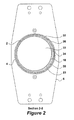
- Figure 2 shows a cross-sectional view through the former set taking along line 2-2 of Figure 1;
- Figure 3 shows a perspective view of the fill tube of Figure 1, viewed from the lower end;
- Figure 4 shows a perspective view of the lower end of the fill tube of Figure 3.
- Figure 5 shows a longitudinal cross-section through the seal bar of Figure 4 along line 5-5 .
- FIG. 1 there is shown a perspective view of a former set 1 for a vertical fill/seal packaging machine according to one aspect of the present invention.
- the former set 1 comprises a fill tube 2 comprising an elongate generally cylindrical body 3.
- a forming collar 4 is provided around the fill tube 2 and both the fill tube 2 and the forming collar 4 are held in spaced concentric relation by a suspension frame 6.
- the suspension frame 6 also serves to support the former set 1 within a packaging machine (not shown).
- An elongate seal plate 10 is provided on the exterior of the fill tube 2, extending to a lower end 12 thereof.
- Towards an upper end 14 of the fill tube 2 there is provided a gas nozzle 16.
- the fill tube 2 has a friction reducing outer surface 26.
- Figure 2 shows a cross-section through the fill tube 2 of Figure 1, taken along line 2-2 .
- the fill tube 2 comprises a relatively thick inner part 18, a relatively thin outer part 20 and a friction reducing outer surface 26.
- the fill tube 2 also comprises a bore 22, which extends from the upper end 14 to the lower end 12.
- the bore 22 is arranged eccentrically with respect to the inner part 18.
- a gas flushing channel 24 extends longitudinally through the thickest region of the wall 23.
- the gas flushing channel 24 extends from the gas nozzle 16, to an outlet 25 ( Figure 3) in the bore 22 adjacent to the lower end 12.
- an annular gap 32 formed between an outer surface of the fill tube 2 and the forming collar 4.
- the inner part 18 of the fill tube 2 is made out of PVDF.
- the outer part 20 comprises polyamide. Other materials may also be used, to the extent that they meet food hygiene standards. In particular, stainless steel and aluminium may be used for the inner part 18 and their combination with an outer part 20 formed of polyamide is considered to be extremely advantageous especially for hard and abrasive products such as frozen foods.
- the fill tube has an outer diameter of about 16 cm and a length of about 90 cm.
- the bore diameter is about 14.5 cm and the thickness of the wall 23 varies from about 0.5 cm to 1 cm in the region of the gas flushing channel 24. It will be immediately evident that other dimensions may also be used according to the packaging requirements. Typical dimensions may range from 4 to 25 cm in outer diameter and 60 to 150 cm in length.
- the forming collar 4 is formed of fibre reinforced epoxy material, coated with a non-stick wolfram disulfide coating. It is understood that other materials may be used including stainless steel and aluminum.
- the suspension frame 6 is also manufactured from polymeric materials. Nevertheless, other conventionally used materials can be used, at least for certain component parts thereof.
- Figure 3 shows a perspective view of the fill tube 2 of Figure 1 with the seal bar removed, viewed from the lower end 12.
- a mounting flange 34 can be seen at the upper end 14 for attachment of the tube 2 to the frame 6.
- Figure 3 also shows the manner in which the gas flushing channel 24 is formed by machining a longitudinal groove 30 from the outside of the tube 2 and the outlet 25 into the bore 22.
- the bore 22 is widened to form a socket 36. Studs 38 are located within the socket 36 to form a bayonet attachment for the mounting ring of a bag spreader (not shown).
- Figure 4 shows a close up view of the lower end 12 of the fill tube 2.
- the outer part 20 and inner part 18 are recessed together at this point to avoid undesired separation of or damage to the outer part 20.
- a circumferential groove 28 is formed around the outside of the inner part 18, close to the lower end 12.
- the groove 28 has a relatively abrupt lower edge 40 and tapers away towards the upper end 14 of the fill tube 2.
- the outer part 20 lies intimately against the inner part 18 and terminates at the lower edge 40 of the groove 28. In this manner, the lower extremity of the outer part 20 is protected from damage.
- Figure 4 also shows the extremity of the longitudinal groove 30.
- the longitudinal groove 30 extends completely to the lower end 12 of the fill tube 2. It may however terminate at a distance from the lower end 12. It should also be noted that different grooves could be formed for respectively providing the gas flushing channel 24 and receiving the seal plate 10.
- Figure 5 shows a partial longitudinal cross-section through the fill tube 2 taken along line 5-5 of Figure 4. In this view, the cross section of the circumferential groove 28 may be seen. Also visible in Figure 5 are the friction reducing outer surface 26, which covers both the outer part 20 and the exposed surfaces of the inner part 18 and the internal shape of the socket 36.
- a web 8 of packaging material is fed over the forming collar 4 and drawn downwards through the annular gap 32 to wrap it around the fill tube 2.
- the tubular web 9 is then sealed to itself to form a longitudinal seam by the application of heat and pressure against the seal plate 10 using an appropriate sealing device.
- product to be packaged may be supplied to the bore 22.
- the tubular web 9 may then be sealed closed by cross seals and severed at preset intervals to form individually sealed packages of product.
- a certain type of gas such as nitrogen.
- the gas may be supplied via the gas nozzle 16 and gas flushing channel 24 to the interior of the tubular web as it leaves the lower end 12 of the fill tube 2, prior to forming the cross seal.
Landscapes
- Engineering & Computer Science (AREA)
- Mechanical Engineering (AREA)
- Containers And Plastic Fillers For Packaging (AREA)
Priority Applications (1)
| Application Number | Priority Date | Filing Date | Title |
|---|---|---|---|
| EP06101120A EP1813530A1 (de) | 2006-01-31 | 2006-01-31 | Vorrichtung zum Formen einer Verpackung |
Applications Claiming Priority (1)
| Application Number | Priority Date | Filing Date | Title |
|---|---|---|---|
| EP06101120A EP1813530A1 (de) | 2006-01-31 | 2006-01-31 | Vorrichtung zum Formen einer Verpackung |
Publications (1)
| Publication Number | Publication Date |
|---|---|
| EP1813530A1 true EP1813530A1 (de) | 2007-08-01 |
Family
ID=36589208
Family Applications (1)
| Application Number | Title | Priority Date | Filing Date |
|---|---|---|---|
| EP06101120A Withdrawn EP1813530A1 (de) | 2006-01-31 | 2006-01-31 | Vorrichtung zum Formen einer Verpackung |
Country Status (1)
| Country | Link |
|---|---|
| EP (1) | EP1813530A1 (de) |
Cited By (1)
| Publication number | Priority date | Publication date | Assignee | Title |
|---|---|---|---|---|
| IT202000005068A1 (it) * | 2020-03-10 | 2021-09-10 | Gimsa S R L | Assieme formatore per macchine confezionatrici |
Citations (4)
| Publication number | Priority date | Publication date | Assignee | Title |
|---|---|---|---|---|
| CH373683A (de) * | 1962-11-12 | 1963-11-30 | Sig Schweiz Industrieges | Vorrichtung zum Abfüllen von sperrigem schüttbarem Gut |
| DE10027581A1 (de) * | 2000-06-02 | 2001-12-13 | Hastamat Verpackungstechnik Gm | Schlauchbeutelmaschine zur Herstellung von Beuteln mit Kantensiegelung |
| JP2002002619A (ja) * | 2000-06-26 | 2002-01-09 | Mitsubishi Gas Chem Co Inc | 粉粒体包装体の製造方法及び製造装置 |
| US20030084650A1 (en) * | 2001-10-08 | 2003-05-08 | Gerhard Kuss | Bagging machine to manufacture seal edged bags |
-
2006
- 2006-01-31 EP EP06101120A patent/EP1813530A1/de not_active Withdrawn
Patent Citations (4)
| Publication number | Priority date | Publication date | Assignee | Title |
|---|---|---|---|---|
| CH373683A (de) * | 1962-11-12 | 1963-11-30 | Sig Schweiz Industrieges | Vorrichtung zum Abfüllen von sperrigem schüttbarem Gut |
| DE10027581A1 (de) * | 2000-06-02 | 2001-12-13 | Hastamat Verpackungstechnik Gm | Schlauchbeutelmaschine zur Herstellung von Beuteln mit Kantensiegelung |
| JP2002002619A (ja) * | 2000-06-26 | 2002-01-09 | Mitsubishi Gas Chem Co Inc | 粉粒体包装体の製造方法及び製造装置 |
| US20030084650A1 (en) * | 2001-10-08 | 2003-05-08 | Gerhard Kuss | Bagging machine to manufacture seal edged bags |
Non-Patent Citations (1)
| Title |
|---|
| PATENT ABSTRACTS OF JAPAN vol. 2002, no. 05 3 May 2002 (2002-05-03) * |
Cited By (1)
| Publication number | Priority date | Publication date | Assignee | Title |
|---|---|---|---|---|
| IT202000005068A1 (it) * | 2020-03-10 | 2021-09-10 | Gimsa S R L | Assieme formatore per macchine confezionatrici |
Similar Documents
| Publication | Publication Date | Title |
|---|---|---|
| JP5439495B2 (ja) | ペイントスプレーガン用グラビティカップ | |
| EP2731742B1 (de) | Vertikales semikontinuierliches giessverfahren für mehrere legierungen | |
| US20230047517A1 (en) | Thin-Walled Metal Cup | |
| US20110277581A1 (en) | Delta robot for increased requirements on dynamics, hygiene and protection against the consequences of collision | |
| US20080149215A1 (en) | Device for Loading a Vessel with Solid Particles and Method Using Said Device | |
| US9090364B2 (en) | Method for packaging polycrystalline silicon | |
| CA2462894A1 (en) | Plastic spout | |
| EP1883594B1 (de) | Schienenelement zur förderung hängender objekte, vorformenzufuhrvorrichtung mit einem solchen element | |
| KR102316845B1 (ko) | 가스 와이핑 노즐의 제조 방법 및 가스 와이핑 노즐 | |
| EP1813530A1 (de) | Vorrichtung zum Formen einer Verpackung | |
| CN102172670A (zh) | 复合板材的生产设备和复合钢带 | |
| US20220371805A1 (en) | Shipping System for Shipping Glass Sheets | |
| JP6823607B2 (ja) | 金属溶融浴中で被覆される金属ストリップを偏向又は案内するためのローラ | |
| CN105517907A (zh) | 用于流量控制的装置 | |
| EP4051924A1 (de) | Membranhalter für einen ölpneumatischen stossdämpfer | |
| JP5615999B2 (ja) | 流体噴射式織機における緯糸送り装置 | |
| US9863570B2 (en) | Hopper tee with wear port | |
| MXPA00001827A (es) | Aparato para formar un reborde enrollado hacia afuera en un cuerpo de contenedor cilindrico. | |
| JP4045543B2 (ja) | 部品搬送ホースおよび部品搬送方法 | |
| CN119998048A (zh) | 用于涂覆纤维基中空主体的装置 | |
| EP2024239B1 (de) | Aus kunststoff hergestellte flexible verpackung | |
| CN101896759A (zh) | 管涂层 | |
| EP4656357A1 (de) | Druckrolle einer rollengespeisten verpackungsmaschine | |
| KR20210061931A (ko) | 스테인리스 강대가 포함된 복합관 | |
| CN218618961U (zh) | 送料装置 |
Legal Events
| Date | Code | Title | Description |
|---|---|---|---|
| PUAI | Public reference made under article 153(3) epc to a published international application that has entered the european phase |
Free format text: ORIGINAL CODE: 0009012 |
|
| AK | Designated contracting states |
Kind code of ref document: A1 Designated state(s): AT BE BG CH CY CZ DE DK EE ES FI FR GB GR HU IE IS IT LI LT LU LV MC NL PL PT RO SE SI SK TR |
|
| AX | Request for extension of the european patent |
Extension state: AL BA HR MK YU |
|
| 17P | Request for examination filed |
Effective date: 20080130 |
|
| AKX | Designation fees paid |
Designated state(s): AT BE BG CH CY CZ DE DK EE ES FI FR GB GR HU IE IS IT LI LT LU LV MC NL PL PT RO SE SI SK TR |
|
| GRAP | Despatch of communication of intention to grant a patent |
Free format text: ORIGINAL CODE: EPIDOSNIGR1 |
|
| STAA | Information on the status of an ep patent application or granted ep patent |
Free format text: STATUS: THE APPLICATION IS DEEMED TO BE WITHDRAWN |
|
| 18D | Application deemed to be withdrawn |
Effective date: 20090616 |