EP1813739A2 - Modulare Struktur für Friedhofkonstruktionen - Google Patents
Modulare Struktur für Friedhofkonstruktionen Download PDFInfo
- Publication number
- EP1813739A2 EP1813739A2 EP07001117A EP07001117A EP1813739A2 EP 1813739 A2 EP1813739 A2 EP 1813739A2 EP 07001117 A EP07001117 A EP 07001117A EP 07001117 A EP07001117 A EP 07001117A EP 1813739 A2 EP1813739 A2 EP 1813739A2
- Authority
- EP
- European Patent Office
- Prior art keywords
- modular structure
- panels
- joints
- module
- structure according
- Prior art date
- Legal status (The legal status is an assumption and is not a legal conclusion. Google has not performed a legal analysis and makes no representation as to the accuracy of the status listed.)
- Granted
Links
Images

Classifications
-
- E—FIXED CONSTRUCTIONS
- E04—BUILDING
- E04H—BUILDINGS OR LIKE STRUCTURES FOR PARTICULAR PURPOSES; SWIMMING OR SPLASH BATHS OR POOLS; MASTS; FENCING; TENTS OR CANOPIES, IN GENERAL
- E04H13/00—Monuments; Tombs; Burial vaults; Columbaria
- E04H13/008—Memorials for cremation ashes
-
- E—FIXED CONSTRUCTIONS
- E04—BUILDING
- E04H—BUILDINGS OR LIKE STRUCTURES FOR PARTICULAR PURPOSES; SWIMMING OR SPLASH BATHS OR POOLS; MASTS; FENCING; TENTS OR CANOPIES, IN GENERAL
- E04H13/00—Monuments; Tombs; Burial vaults; Columbaria
- E04H13/006—Columbaria, mausoleum with frontal access to vaults
Definitions
- the present invention refers to a modular structure for cemetery constructions.
- the modular structure of the present invention has a preferred though not exclusive application in the cemetery constructions composed of a series of niches or ossuaries (simply indicated with the term “niches” herein below).
- such cemetery constructions are generally composed of a building structure formed of a multiplicity of niches, having the same dimensions and placed adjacent and/or superimposed on each other.
- the niches are of parallelepiped form, delimited by four walls and by two covers placed at the opposite ends of such walls. Each wall of a niche is in contact with a corresponding wall of the adjacent niche, when such adjacent niche is present.
- the niches are generally arranged such that, for each niche, only one of such covers is visible from the outside.
- the niches are internally empty; by means of the removal of one of such covers, generally the one which is externally visible, it is possible to insert coffins or cinerary urns inside their interior.
- Such cemetery constructions are concrete structures, made on site by means of the construction of wooden forms and the subsequent filling operation of the same with reinforced concrete casting.
- This building system has several disadvantages, such as for example: 1) the need to set up a building yard in the building zone inside a cemetery, producing troubling dirt, dust or dangerous conditions for cemetery visitors; 2) long building times; 3) the need to use cranes or other machinery for the movement of heavy materials; 4) making a final structure with very heavy weight; 5) not entirely satisfactory water-resistance, especially long-term.
- one problem underlying the present invention in a first aspect, is that of providing the elements for making a cemetery structure which can be made on site, being easily adapted to the available spaces, without having to set up a complex building yard and use cranes or other machinery for the movement of material and for structure assembly.
- a problem of the present invention is to realize a cemetery structure in a short period of time.
- a problem of the present invention is to realize a cemetery structure having a reduced weight, maintaining at the same time the robustness, rigidity and impact strength features.
- a problem of the present invention is to reduce the space between one niche and the other one, either horizontally or vertically, therefore allowing to increase the number of niches which can be made within the available space.
- a problem of the present invention is to realize a cemetery construction having greater water resistance and chemical agents corrosion with respect to convention cemetery constructions, especially long-term.
- the invention therefore regards a modular structure for cemetery constructions according to claim 1. Preferred characteristics are indicated in the dependent claims.
- the invention refers to a modular structure for cemetery constructions comprising at least one module of substantially parallelepiped form wherein the module comprises:
- module of substantially parallelepiped form is intended a module of parallelepiped form, of cubic form (i.e. a particular parallelepiped form wherein all the faces have the same dimensions), or a form which can be considered as such overall, even if not being perfectly parallelepiped or cubic. It is also intended that, in order to obtain such a module of substantially parallelepiped or cubic form, each of said four panels forms a wall of the module substantially arranged at 90° with respect to the two consecutive walls, wherein for "substantially at 90°” it is intended at 90° or with a percentage of difference from 90° equal to about 1-2%.
- module is intended a structure composed of a plurality of rows of said modules, each row being superimposed to the other, and wherein each of said row of module is composed of a plurality of said modules arranged one adjacent to the other.
- each of said row of module is composed of the same number of modules, in such a way that the modular structure of the present invention has an overall parallelepiped form, composed of a certain number of rows and a certain number of columns of said modules.
- the modular structure according to the present invention is generically composed of 2-20 of said rows, more preferably 3-10, and 2-20 of said columns, preferably 3-10.
- the lower row of said plurality of rows rests directly on a foundation, on a floor or on a base adapted to support the weight of the modular structure of the invention.
- a modular structure according to the present invention is composed of: a) external modules, i.e. modules which belong to one of the two columns or to one of the two rows at the ends of the modular structure, and b) central modules, i.e. modules which belong to one of the inner columns or to one of the inner rows and which are not external modules.
- One advantage associated with the modular structure for cemetery constructions of the present invention consists in the possibility of setting up, on site, the structure elements - panels, joints and covers - to be able to assemble a certain number of modules every time they are needed.
- said panels, covers and joints are made of light material, such as for example a material chosen among fibreglass-reinforced plastic, aluminium and plastic materials, such as PVC and ABS, or in a material which ensures a certain robustness, such as for example iron and stainless steel. More preferably, said panels, covers and joints are made of fibreglass-reinforced plastic or aluminium, obtaining an optimal compromise of robustness, lightness of the material and long-term resistance.
- the modular structure for cemetery constructions of the present invention has the advantage of having a reduced weight with respect to the conventional in concrete cemetery constructions, maintaining at the same time the characteristics of robustness, rigidity and impact strength.
- the modular structure for cemetery constructions of the present invention has also the advantages of facilitating the transport of such elements, not requiring the use of bulky machinery for the preparation of a complex on-site building yard, reducing the building time, and reducing at the same time the disturbances affecting cemetery visitors.
- the four module panels have flattened rectangular form, i.e. a parallelepiped form with reduced thickness.
- the section and thickness of the panels are of such dimensions to obtain the best compromise between the weight of the obtained modular structure and the load strength needs of the modular structure itself.
- said at least one module comprises at least two covers adapted to form the two opposite ends of the module.
- said at least two covers are of substantially square or rectangular form.
- said at least two covers are of substantially square form and are particularly useful for making a "front modular structure", i.e. a modular structure wherein the modules have a greater depth with respect to their width and such that the zone corresponding to one of such substantially square covers only is visible from the outside.
- the length of the side of said covers of substantially square form is substantially equal to the smaller dimension of the four module panels, said four panels all being equivalent.
- said at least two covers are of substantially rectangular form and are particularly useful for making a "side modular structure", i.e. a modular structure composed of a plurality of modules wherein the modules have a lesser depth with respect to their width and such that the zone corresponding to one of such substantially rectangular covers only is visible from the outside.
- the dimensions (a,b) of said covers of substantially rectangular form are substantially equal, respectively, to one of the dimensions (a) of a pair of opposite panels and to one of the dimensions (b) of the other pair of opposite panels, said four panels being substantially two-by-two equal (every panel is substantially equal to its opposite).
- At least one of said four joints is further engaged with a third panel, which is arranged at 90° with respect to one of said two panels (herein indicated as the first panel) and at 180° with respect to the other of said two panels (herein indicated as the second panel). Therefore, said first and said second panel form two consecutive walls of a first module, while said first and third panel form two consecutive walls of a second module placed adjacent to said first module.
- this preferred embodiment of the present invention has a modular structure comprising a first and a second module placed adjacent to each other and having one wall in common formed by said first panel, with the advantage of reducing the space between two adjacent modules and better taking advantage of the space available for the making of the cemetery structure.
- At least one of said four joints is further engaged with a fourth panel arranged 90° with respect to said third panel.
- said third and fourth panel form two consecutive walls of a third module placed adjacent to said second module, and moreover said fourth and said second panel form two consecutive walls of a fourth module placed adjacent to said third module and at the same time placed adjacent to said first module.
- the modular structure has the advantage of having at least one joint which is engaged with four panels, each of them forms a wall common to two adjacent modules.
- each of the four modules mentioned above will be completed with the use of panels and joints in such a number and position to obtain the required parallelepiped structure.
- This embodiment in which at least one joint is engaged with four panels is particularly useful for contributing to the formation of at least three modules. More in particular, it is useful for contributing to the formation of four modules, both in the case in which all the four modules are internal modules and in the case in which there are one or two internal modules and, respectively, three or two external modules.
- said four panels are provided with a first coupling profile having U-shaped section, placed in external position with respect to at least one edge of the panel.
- said four panels are provided with a first and a second coupling profile having U-shaped section, in external position with respect to two opposite edges of the panel.
- the joints have a core portion having parallelepiped form with substantially square base.
- the dimension of the side of the core portion is substantially equal to the thickness of said panels and the length of said joints is substantially equal to the length of the edges of said panels.
- said joints have at least two (more preferably, three, and still more preferably four) coupling profiles having U-shaped section, in external position with respect to the core.
- said joints have a substantially cross-shaped transverse section.
- the coupling profile of said panels is engaged with the coupling profile of said joints.
- said joints have at least one groove, preferably two grooves, at one of the parallel elements of said coupling profile having U-shaped section, said at least one groove being adapted to be engaged with said coupling profile of said panels.
- said panels and said joints are engaged to obtain an even better seal.
- said grooves allow the collection of a possible structural glue employed for sealing the joints.
- said joints have said coupling profiles having, at one end thereof, a rib or protuberance adapted to engage with a corresponding groove present on said coupling profile of said panels.
- said panels and said joints engage to be self-locked, preventing the sliding of one with respect to the other, and allowing the modular structure to have an aligned and correct self-positioning.
- said joints have a central hole.
- a threaded bush is foreseen to allow the positioning of support bosses of marble plates or the like.
- At least one of said covers of the modular structure of the present invention has two diagonal ribs for improving the lateral thrust strength of the entire modular structure and shearing strength.
- each of said covers has a connection edge adapted to engage with the edges of the walls of each module. By this way the gluing and sealing is allowed.
- FIG 1 A preferred embodiment of the present invention is shown in figure 1, wherein a modular structure 1 is shown for cemetery constructions, formed by three superimposed rows of modules 2, each of them being formed by five modules 2 placed adjacent one to each other, for a total of fifteen modules 2. All modules 2 have the same parallelepiped form and the same dimensions. As is evident from figure 1, the modules 2 of the modular structure 1 can be subdivided into external modules 2a and internal modules 2b; it is to be noted that - in the text and in the drawings - with the number 2 reference is made either to external modules 2a or internal modules 2b. Each of such modules 2, whether external 2a or internal 2b, is formed by four panels 4 forming the walls of the module 2, by four joints 5, and by two square form covers 6 forming the end and front wall of the module 2.
- each pair of adjacent modules 2 has a wall 4 in common. This characteristic leads to the advantage of reducing the total weight of the modular structure 1 and reducing to a minimum the space between one module 2 and the other one, with the consequence to be able to realize a structure 1 with a greater number of niches.
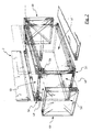
- the module 2 whether external 2a or internal 2b, comprises four panels 4a, 4b, 4c and 4d, four joints 5a, 5b, 5c and 5d, and two covers 6a and 6b; it is to be noted that - in the text and in the drawings - with the numbers 4, 5 and 6 reference is indiscriminately made to the specific elements 4a, 4b, 4c, 4d, 5a, 5b, 5c, 5d, 6a, 6b.
- the four panels 4a, 4b, 4c and 4d form the walls of the module 2 and each of said panels is placed at 90° with respect to the subsequent panel.
- each joint 5 of the module 2 is engaged with two panels 4 forming two consecutive walls of the same module 2: in fact, the joint 5a is engaged with the panels 4a and 4b, the joint 5b is engaged with the panels 4b and 4c, the joint 5c is engaged with the panels 4c and 4d, and the joint 5d is engaged with the panels 4d and 4a.
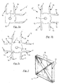
- each joint 5 comprises a central core 15, of square section, and two to four coupling profiles 16 having U-shaped section, in external position with respect to the core 15.
- the joint 5' shown in figure 3a comprises two coupling profiles 16; this can thus be engaged with two panels 4 of a same module 2 and is therefore particularly useful for making a corner of an external module 2a (see figure 1).
- the joint 5" shown in figure 3b comprises three coupling profiles 16; it can thus be engaged with two panels 4 of a same module 2 and with a third panel 4 of a second module 2, such third panel 4 being arranged respectively at 90° and at 180° with respect to the other two panels 4.
- the joint 5 shown in figure 3c has four coupling profiles 16; it can thus be engaged with four panels 4, and is particularly useful for making up to maximum of four modules 2.
- a modular structure 1 for cemetery structures can be composed by modules 2 all having joint 5, shown in figure 3c, even for the positions where it would be more logical to use a joint 5' or a joint 5".
- joint 5 shown in figure 3c is intended to be engaged with only two panels 4 for making, for example, a corner of an external module 2a
- such joint 5 will have two coupling profiles 16 which remain free
- three panels 4 for making, for example, an external wall of an external module 2a such joint 5 will have one coupling profile 16 which remains free.
- a preferred embodiment of a modular structure 1 of the present invention has the panels 4a and 4b of a module 2 of flattened rectangular form, i.e. parallelepiped with a very thin thickness.
- the panels 4 have a coupling profile 14 along one of their edges.
- Such coupling profiles 14 of the panels 4 are intended to engage with the coupling profiles 16 present on the joints 5.
- the coupling profiles 16 present on the joint 5 are provided with two grooves 3.
- Such grooves 3 have the double object of collecting structural glue possibly employed for sealing the junctions and to allow the coupling profile 14 of the panels 4 to engage with joint 5 with even better results.
- each joint 5 is provided with ribs 7 (figures 3 and 4) present on the coupling profile 16 adapted to be engaged with corresponding grooves 8 present on the coupling profile 14 of the panels 4.
- the panels 4 and the joints 5 engage to be self-locked, preventing the sliding of one towards the other one, and allowing the modular structure 1 to have an aligned and correct self-positioning.
- the joint 5 comprises a central hole 9 formed in the core 15, possibly provided with a threaded bush (not shown in the figures) to allow the positioning of support bosses for plates of marble, stone, granite or the like.
- the modular structure 1 moreover comprises a cover 6, provided with two diagonal ribs 10 for improving the entire modular structure's lateral thrust strength and shearing strength.
- the cover 6 has also a connection edge 12 adapted to engage with the edges of the walls 4 of the module 2. By this way, gluing and sealing is permitted.
- modular structures are also intended as falling within the scope of the present invention in which one module is composed of at least one element which overall has substantially the same form obtainable by single elements composing the module of the structure of the present invention and which carries out the same function of such assembled single elements.
Landscapes
- Engineering & Computer Science (AREA)
- Architecture (AREA)
- Civil Engineering (AREA)
- Structural Engineering (AREA)
- Assembled Shelves (AREA)
- Finishing Walls (AREA)
- Executing Machine-Instructions (AREA)
- Tents Or Canopies (AREA)
- Connection Of Plates (AREA)
- Safety Valves (AREA)
- Prostheses (AREA)
- Mirrors, Picture Frames, Photograph Stands, And Related Fastening Devices (AREA)
- Measuring Instrument Details And Bridges, And Automatic Balancing Devices (AREA)
- Measurement Of Resistance Or Impedance (AREA)
Applications Claiming Priority (1)
| Application Number | Priority Date | Filing Date | Title |
|---|---|---|---|
| IT000145A ITMI20060145A1 (it) | 2006-01-27 | 2006-01-27 | Struttura modulare per costruzioni cimiteriali |
Publications (4)
| Publication Number | Publication Date |
|---|---|
| EP1813739A2 true EP1813739A2 (de) | 2007-08-01 |
| EP1813739A3 EP1813739A3 (de) | 2009-01-07 |
| EP1813739B1 EP1813739B1 (de) | 2010-12-01 |
| EP1813739B8 EP1813739B8 (de) | 2011-03-02 |
Family
ID=37998299
Family Applications (1)
| Application Number | Title | Priority Date | Filing Date |
|---|---|---|---|
| EP07001117A Active EP1813739B8 (de) | 2006-01-27 | 2007-01-19 | Grabmal mit modularer Struktur |
Country Status (7)
| Country | Link |
|---|---|
| US (1) | US7591053B2 (de) |
| EP (1) | EP1813739B8 (de) |
| AT (1) | ATE490388T1 (de) |
| AU (1) | AU2007200420A1 (de) |
| DE (1) | DE602007010843D1 (de) |
| ES (1) | ES2356508T3 (de) |
| IT (1) | ITMI20060145A1 (de) |
Cited By (2)
| Publication number | Priority date | Publication date | Assignee | Title |
|---|---|---|---|---|
| ES2536333A1 (es) * | 2013-11-20 | 2015-05-22 | Miguel Ángel RIGUEIRA RODRÍGUEZ | Mausoleo funerario con nichos prefabricados |
| EP2921601A3 (de) * | 2014-03-21 | 2015-10-21 | Rivestimenti Plastici S.r.l. | Vorgefertigte modulare struktur für friedhöfe |
Families Citing this family (22)
| Publication number | Priority date | Publication date | Assignee | Title |
|---|---|---|---|---|
| ES1067502Y (es) * | 2008-03-11 | 2008-08-16 | Marcs Urnas Bach S L | Columbario modular |
| US20100012606A1 (en) * | 2008-07-16 | 2010-01-21 | Bourgo Henry M | Urn and urn system |
| US9080344B2 (en) | 2009-04-30 | 2015-07-14 | Matthews Resources, Inc. | Modular crypt and modular crypt system with niche side wall |
| US9249598B2 (en) * | 2009-04-30 | 2016-02-02 | Matthews Resources, Inc. | Modular crypt |
| US8782969B2 (en) * | 2009-06-02 | 2014-07-22 | Eickhof Columbaria Inc. | Columbarium construction and shutter mounting system |
| US9016485B1 (en) * | 2014-06-13 | 2015-04-28 | Sun Yu Ta Co. Ltd. | Combination rack structure |
| US7926228B1 (en) | 2010-10-08 | 2011-04-19 | Snow William L | Cremation niche |
| ITCR20120021A1 (it) * | 2012-10-09 | 2014-04-10 | Mario Dalseno | Struttura prefabbricata per costruzioni cimiteriali |
| USD750955S1 (en) * | 2013-01-10 | 2016-03-08 | Mausoleum, S.A. De C.V. | Mechanical connector |
| USD745820S1 (en) * | 2013-02-06 | 2015-12-22 | Mausoleum S.A. De C.V. | Connector |
| GB2523190B (en) * | 2014-02-18 | 2016-04-20 | Adler & Allan Ltd | Modular bund system and method of installing a modular bund system |
| MX348913B (es) * | 2014-04-23 | 2017-07-04 | Mausoleum S A De C V | Sistema modular de nichos o criptas para el depósito de cenizas y/o restos áridos. |
| US9777501B2 (en) * | 2015-12-29 | 2017-10-03 | Biondan North America Inc. | Structure for containing cinerary urns and furnerary items in general |
| US10422126B2 (en) * | 2016-07-26 | 2019-09-24 | Robert Jeffrey Kupferberg | Compression seal groove connector |
| USD922862S1 (en) * | 2018-01-29 | 2021-06-22 | Columbarium By Design, Llc | Niche bracket |
| US11136782B2 (en) | 2018-05-31 | 2021-10-05 | Biondan North America Inc. | Funerary structure for containing funerary objects |
| IT201800005885A1 (it) * | 2018-05-31 | 2019-12-01 | Struttura funeraria per il contenimento di oggetti funerari. | |
| ES1218996Y (es) * | 2018-08-29 | 2019-01-25 | Coral Smart Invex S L | Columbario modular para el almacenamiento de urnas funerarias y recipiente individual |
| USD873122S1 (en) * | 2018-09-22 | 2020-01-21 | Won Yong Cho | Shelf joint |
| US12397986B2 (en) * | 2021-01-22 | 2025-08-26 | PRO blanket bars GmbH | Collapsible containers including edge attachment brackets |
| USD1003700S1 (en) * | 2021-05-26 | 2023-11-07 | Ecosystems Brand Llc | Connector |
| USD1012322S1 (en) * | 2021-07-22 | 2024-01-23 | Mccleskey Professional Services | Mausoleum |
Family Cites Families (16)
| Publication number | Priority date | Publication date | Assignee | Title |
|---|---|---|---|---|
| GB144813A (en) * | 1919-03-20 | 1920-06-21 | George Colvin Kennedy | Improvements in the construction of mausoleum chambers |
| US2388297A (en) * | 1941-07-10 | 1945-11-06 | Extruded Plastics Inc | Composite article, including extruded sections |
| US3351366A (en) * | 1965-10-24 | 1967-11-07 | Greenberg S Sons M | Interlocking joint |
| US3661434A (en) * | 1970-05-28 | 1972-05-09 | Ralph Alster | Unitary modular shelving structure |
| US3754805A (en) * | 1971-11-15 | 1973-08-28 | Matthews J & Co | Urn storage assembly |
| US3841726A (en) * | 1973-04-13 | 1974-10-15 | Matthews H & Co | Urn storage assembly |
| US4073100A (en) * | 1976-07-21 | 1978-02-14 | Digiovanni Jr Francis J | Mausoleum and method of construction |
| US4614066A (en) * | 1985-12-09 | 1986-09-30 | Koppenberg Bruce G | Modular columbarium structure |
| US4828132A (en) * | 1987-07-28 | 1989-05-09 | United States Corrulite Corporation | Collapsible reusable containers, wall sleeves and hinges therefor |
| US4907713A (en) * | 1989-03-27 | 1990-03-13 | Motorola, Inc. | Electronic housing module |
| US5477594A (en) * | 1993-12-29 | 1995-12-26 | Christian Memorial Cultural Center | Niche panel |
| US5377857A (en) * | 1994-01-13 | 1995-01-03 | Anchor Bay Packaging Corporation | Stackable bin with collapsible corner construction |
| US5466057A (en) * | 1994-03-16 | 1995-11-14 | Blankenburg; Karl | Modular storage apparatus |
| US5638973A (en) * | 1996-05-09 | 1997-06-17 | Western Poly Corporation | Storage container with interlocking corner members |
| US5722551A (en) * | 1996-07-19 | 1998-03-03 | Cocciemiglio, Jr.; Dominick | Crate assembly and panel connecting clip |
| US5996828A (en) * | 1998-10-09 | 1999-12-07 | Cheyn; Ruey Chyuan | Corner assembly for a box |
-
2006
- 2006-01-27 IT IT000145A patent/ITMI20060145A1/it unknown
-
2007
- 2007-01-19 DE DE602007010843T patent/DE602007010843D1/de active Active
- 2007-01-19 AT AT07001117T patent/ATE490388T1/de not_active IP Right Cessation
- 2007-01-19 EP EP07001117A patent/EP1813739B8/de active Active
- 2007-01-19 ES ES07001117T patent/ES2356508T3/es active Active
- 2007-01-24 US US11/657,500 patent/US7591053B2/en active Active
- 2007-01-25 AU AU2007200420A patent/AU2007200420A1/en not_active Abandoned
Cited By (2)
| Publication number | Priority date | Publication date | Assignee | Title |
|---|---|---|---|---|
| ES2536333A1 (es) * | 2013-11-20 | 2015-05-22 | Miguel Ángel RIGUEIRA RODRÍGUEZ | Mausoleo funerario con nichos prefabricados |
| EP2921601A3 (de) * | 2014-03-21 | 2015-10-21 | Rivestimenti Plastici S.r.l. | Vorgefertigte modulare struktur für friedhöfe |
Also Published As
| Publication number | Publication date |
|---|---|
| ATE490388T1 (de) | 2010-12-15 |
| US20070175110A1 (en) | 2007-08-02 |
| AU2007200420A1 (en) | 2007-08-16 |
| ES2356508T3 (es) | 2011-04-08 |
| ITMI20060145A1 (it) | 2007-07-28 |
| US7591053B2 (en) | 2009-09-22 |
| EP1813739A3 (de) | 2009-01-07 |
| DE602007010843D1 (de) | 2011-01-13 |
| EP1813739B8 (de) | 2011-03-02 |
| EP1813739B1 (de) | 2010-12-01 |
Similar Documents
| Publication | Publication Date | Title |
|---|---|---|
| EP1813739B1 (de) | Grabmal mit modularer Struktur | |
| US11332921B2 (en) | Construction system for a building module | |
| KR101656039B1 (ko) | 내화구조의 바닥 슬라브를 갖는 건축용 컨테이너 모듈 및 이를 포함하는 건축물 | |
| KR100952605B1 (ko) | 우수 저류조 | |
| US20070130854A1 (en) | Web offset lug dry-stack system | |
| US4648226A (en) | Glass element, notably glass block or tile | |
| KR101264920B1 (ko) | 내진 무몰타르 조립식 블록 시스템 및 벽체 시공방법 | |
| EP2738316A1 (de) | Modulares konstruktionssystem | |
| CA2696981A1 (en) | Building block system | |
| KR20120020254A (ko) | 내진 무몰타르 조립식 블록 시스템 및 벽체 시공방법 | |
| US20130160379A1 (en) | Methods of Constructing Buildings Using Steel Containers | |
| KR20070032676A (ko) | 평면 구조물을 축조하는 축조 시스템 | |
| US20070277476A1 (en) | Wall Systems | |
| KR102177745B1 (ko) | 기둥식 옥탑 pc 프레임 | |
| KR101385554B1 (ko) | 하프 슬라브를 이용한 조립식 건축구조물 | |
| KR100220138B1 (ko) | 조립건물의 시공법 및 그 조립부재 | |
| JP7068143B2 (ja) | 建物 | |
| KR102247573B1 (ko) | 건축물의 벽체구조 | |
| WO2001063068A1 (en) | Set of building modules | |
| JP2021099029A (ja) | 木製壁材及びそれを用いた木造建築物 | |
| US7118309B2 (en) | Component for spatial grid supporting systems comprising filler material especially for retaining walls or noise-abatement walls, and corresponding structure | |
| WO2021009576A1 (en) | Spherical structures consisting of triangular panels | |
| KR102854680B1 (ko) | 건식바닥판이 구비된 모듈러 유닛 | |
| KR200415136Y1 (ko) | 건축용 블럭 조립체 | |
| JP3044094U (ja) | ユニット組立式塀構造及び生垣塀構造 |
Legal Events
| Date | Code | Title | Description |
|---|---|---|---|
| PUAI | Public reference made under article 153(3) epc to a published international application that has entered the european phase |
Free format text: ORIGINAL CODE: 0009012 |
|
| AK | Designated contracting states |
Kind code of ref document: A2 Designated state(s): AT BE BG CH CY CZ DE DK EE ES FI FR GB GR HU IE IS IT LI LT LU LV MC NL PL PT RO SE SI SK TR |
|
| AX | Request for extension of the european patent |
Extension state: AL BA HR MK YU |
|
| PUAL | Search report despatched |
Free format text: ORIGINAL CODE: 0009013 |
|
| AK | Designated contracting states |
Kind code of ref document: A3 Designated state(s): AT BE BG CH CY CZ DE DK EE ES FI FR GB GR HU IE IS IT LI LT LU LV MC NL PL PT RO SE SI SK TR |
|
| AX | Request for extension of the european patent |
Extension state: AL BA HR MK RS |
|
| 17P | Request for examination filed |
Effective date: 20090624 |
|
| 17Q | First examination report despatched |
Effective date: 20090723 |
|
| AKX | Designation fees paid |
Designated state(s): AT BE BG CH CY CZ DE DK EE ES FI FR GB GR HU IE IS IT LI LT LU LV MC NL PL PT RO SE SI SK TR |
|
| GRAP | Despatch of communication of intention to grant a patent |
Free format text: ORIGINAL CODE: EPIDOSNIGR1 |
|
| RTI1 | Title (correction) |
Free format text: MODULAR CEMETERY CONSTRUCTION STRUCTURE |
|
| GRAS | Grant fee paid |
Free format text: ORIGINAL CODE: EPIDOSNIGR3 |
|
| GRAA | (expected) grant |
Free format text: ORIGINAL CODE: 0009210 |
|
| RAP1 | Party data changed (applicant data changed or rights of an application transferred) |
Owner name: GIUSEPPE BOSISIO S.R.L. |
|
| AK | Designated contracting states |
Kind code of ref document: B1 Designated state(s): AT BE BG CH CY CZ DE DK EE ES FI FR GB GR HU IE IS IT LI LT LU LV MC NL PL PT RO SE SI SK TR |
|
| REG | Reference to a national code |
Ref country code: GB Ref legal event code: FG4D |
|
| REG | Reference to a national code |
Ref country code: CH Ref legal event code: EP |
|
| REG | Reference to a national code |
Ref country code: IE Ref legal event code: FG4D |
|
| REF | Corresponds to: |
Ref document number: 602007010843 Country of ref document: DE Date of ref document: 20110113 Kind code of ref document: P |
|
| RIN2 | Information on inventor provided after grant (corrected) |
Inventor name: BOSISIO, RICCARDO Inventor name: BOSISIO, BARBARA |
|
| REG | Reference to a national code |
Ref country code: NL Ref legal event code: VDEP Effective date: 20101201 |
|
| REG | Reference to a national code |
Ref country code: ES Ref legal event code: FG2A Ref document number: 2356508 Country of ref document: ES Kind code of ref document: T3 Effective date: 20110408 |
|
| PG25 | Lapsed in a contracting state [announced via postgrant information from national office to epo] |
Ref country code: LT Free format text: LAPSE BECAUSE OF FAILURE TO SUBMIT A TRANSLATION OF THE DESCRIPTION OR TO PAY THE FEE WITHIN THE PRESCRIBED TIME-LIMIT Effective date: 20101201 |
|
| LTIE | Lt: invalidation of european patent or patent extension |
Effective date: 20101201 |
|
| PG25 | Lapsed in a contracting state [announced via postgrant information from national office to epo] |
Ref country code: NL Free format text: LAPSE BECAUSE OF FAILURE TO SUBMIT A TRANSLATION OF THE DESCRIPTION OR TO PAY THE FEE WITHIN THE PRESCRIBED TIME-LIMIT Effective date: 20101201 Ref country code: LV Free format text: LAPSE BECAUSE OF FAILURE TO SUBMIT A TRANSLATION OF THE DESCRIPTION OR TO PAY THE FEE WITHIN THE PRESCRIBED TIME-LIMIT Effective date: 20101201 Ref country code: AT Free format text: LAPSE BECAUSE OF FAILURE TO SUBMIT A TRANSLATION OF THE DESCRIPTION OR TO PAY THE FEE WITHIN THE PRESCRIBED TIME-LIMIT Effective date: 20101201 Ref country code: FI Free format text: LAPSE BECAUSE OF FAILURE TO SUBMIT A TRANSLATION OF THE DESCRIPTION OR TO PAY THE FEE WITHIN THE PRESCRIBED TIME-LIMIT Effective date: 20101201 Ref country code: SE Free format text: LAPSE BECAUSE OF FAILURE TO SUBMIT A TRANSLATION OF THE DESCRIPTION OR TO PAY THE FEE WITHIN THE PRESCRIBED TIME-LIMIT Effective date: 20101201 Ref country code: BG Free format text: LAPSE BECAUSE OF FAILURE TO SUBMIT A TRANSLATION OF THE DESCRIPTION OR TO PAY THE FEE WITHIN THE PRESCRIBED TIME-LIMIT Effective date: 20110301 Ref country code: CY Free format text: LAPSE BECAUSE OF FAILURE TO SUBMIT A TRANSLATION OF THE DESCRIPTION OR TO PAY THE FEE WITHIN THE PRESCRIBED TIME-LIMIT Effective date: 20101201 Ref country code: SI Free format text: LAPSE BECAUSE OF FAILURE TO SUBMIT A TRANSLATION OF THE DESCRIPTION OR TO PAY THE FEE WITHIN THE PRESCRIBED TIME-LIMIT Effective date: 20101201 |
|
| PG25 | Lapsed in a contracting state [announced via postgrant information from national office to epo] |
Ref country code: GR Free format text: LAPSE BECAUSE OF FAILURE TO SUBMIT A TRANSLATION OF THE DESCRIPTION OR TO PAY THE FEE WITHIN THE PRESCRIBED TIME-LIMIT Effective date: 20110302 |
|
| PG25 | Lapsed in a contracting state [announced via postgrant information from national office to epo] |
Ref country code: EE Free format text: LAPSE BECAUSE OF FAILURE TO SUBMIT A TRANSLATION OF THE DESCRIPTION OR TO PAY THE FEE WITHIN THE PRESCRIBED TIME-LIMIT Effective date: 20101201 Ref country code: BE Free format text: LAPSE BECAUSE OF FAILURE TO SUBMIT A TRANSLATION OF THE DESCRIPTION OR TO PAY THE FEE WITHIN THE PRESCRIBED TIME-LIMIT Effective date: 20101201 Ref country code: IS Free format text: LAPSE BECAUSE OF FAILURE TO SUBMIT A TRANSLATION OF THE DESCRIPTION OR TO PAY THE FEE WITHIN THE PRESCRIBED TIME-LIMIT Effective date: 20110401 Ref country code: PT Free format text: LAPSE BECAUSE OF FAILURE TO SUBMIT A TRANSLATION OF THE DESCRIPTION OR TO PAY THE FEE WITHIN THE PRESCRIBED TIME-LIMIT Effective date: 20110401 Ref country code: CZ Free format text: LAPSE BECAUSE OF FAILURE TO SUBMIT A TRANSLATION OF THE DESCRIPTION OR TO PAY THE FEE WITHIN THE PRESCRIBED TIME-LIMIT Effective date: 20101201 |
|
| PG25 | Lapsed in a contracting state [announced via postgrant information from national office to epo] |
Ref country code: SK Free format text: LAPSE BECAUSE OF FAILURE TO SUBMIT A TRANSLATION OF THE DESCRIPTION OR TO PAY THE FEE WITHIN THE PRESCRIBED TIME-LIMIT Effective date: 20101201 Ref country code: PL Free format text: LAPSE BECAUSE OF FAILURE TO SUBMIT A TRANSLATION OF THE DESCRIPTION OR TO PAY THE FEE WITHIN THE PRESCRIBED TIME-LIMIT Effective date: 20101201 Ref country code: RO Free format text: LAPSE BECAUSE OF FAILURE TO SUBMIT A TRANSLATION OF THE DESCRIPTION OR TO PAY THE FEE WITHIN THE PRESCRIBED TIME-LIMIT Effective date: 20101201 Ref country code: MC Free format text: LAPSE BECAUSE OF NON-PAYMENT OF DUE FEES Effective date: 20110131 |
|
| REG | Reference to a national code |
Ref country code: CH Ref legal event code: PL |
|
| PLBE | No opposition filed within time limit |
Free format text: ORIGINAL CODE: 0009261 |
|
| STAA | Information on the status of an ep patent application or granted ep patent |
Free format text: STATUS: NO OPPOSITION FILED WITHIN TIME LIMIT |
|
| REG | Reference to a national code |
Ref country code: FR Ref legal event code: ST Effective date: 20110930 |
|
| REG | Reference to a national code |
Ref country code: IE Ref legal event code: MM4A |
|
| PG25 | Lapsed in a contracting state [announced via postgrant information from national office to epo] |
Ref country code: LI Free format text: LAPSE BECAUSE OF NON-PAYMENT OF DUE FEES Effective date: 20110131 Ref country code: FR Free format text: LAPSE BECAUSE OF NON-PAYMENT OF DUE FEES Effective date: 20110201 Ref country code: CH Free format text: LAPSE BECAUSE OF NON-PAYMENT OF DUE FEES Effective date: 20110131 Ref country code: DK Free format text: LAPSE BECAUSE OF FAILURE TO SUBMIT A TRANSLATION OF THE DESCRIPTION OR TO PAY THE FEE WITHIN THE PRESCRIBED TIME-LIMIT Effective date: 20101201 |
|
| 26N | No opposition filed |
Effective date: 20110902 |
|
| REG | Reference to a national code |
Ref country code: DE Ref legal event code: R119 Ref document number: 602007010843 Country of ref document: DE Effective date: 20110802 |
|
| PG25 | Lapsed in a contracting state [announced via postgrant information from national office to epo] |
Ref country code: IE Free format text: LAPSE BECAUSE OF NON-PAYMENT OF DUE FEES Effective date: 20110119 |
|
| PG25 | Lapsed in a contracting state [announced via postgrant information from national office to epo] |
Ref country code: LU Free format text: LAPSE BECAUSE OF NON-PAYMENT OF DUE FEES Effective date: 20110119 |
|
| PG25 | Lapsed in a contracting state [announced via postgrant information from national office to epo] |
Ref country code: DE Free format text: LAPSE BECAUSE OF NON-PAYMENT OF DUE FEES Effective date: 20110802 |
|
| PG25 | Lapsed in a contracting state [announced via postgrant information from national office to epo] |
Ref country code: TR Free format text: LAPSE BECAUSE OF FAILURE TO SUBMIT A TRANSLATION OF THE DESCRIPTION OR TO PAY THE FEE WITHIN THE PRESCRIBED TIME-LIMIT Effective date: 20101201 |
|
| PG25 | Lapsed in a contracting state [announced via postgrant information from national office to epo] |
Ref country code: HU Free format text: LAPSE BECAUSE OF FAILURE TO SUBMIT A TRANSLATION OF THE DESCRIPTION OR TO PAY THE FEE WITHIN THE PRESCRIBED TIME-LIMIT Effective date: 20101201 |
|
| P01 | Opt-out of the competence of the unified patent court (upc) registered |
Effective date: 20230515 |
|
| PGFP | Annual fee paid to national office [announced via postgrant information from national office to epo] |
Ref country code: ES Payment date: 20250203 Year of fee payment: 19 |
|
| PGFP | Annual fee paid to national office [announced via postgrant information from national office to epo] |
Ref country code: GB Payment date: 20250127 Year of fee payment: 19 |
|
| PGFP | Annual fee paid to national office [announced via postgrant information from national office to epo] |
Ref country code: IT Payment date: 20260114 Year of fee payment: 20 |