EP1813819B1 - Pompe centrifuge - Google Patents
Pompe centrifuge Download PDFInfo
- Publication number
- EP1813819B1 EP1813819B1 EP07000756A EP07000756A EP1813819B1 EP 1813819 B1 EP1813819 B1 EP 1813819B1 EP 07000756 A EP07000756 A EP 07000756A EP 07000756 A EP07000756 A EP 07000756A EP 1813819 B1 EP1813819 B1 EP 1813819B1
- Authority
- EP
- European Patent Office
- Prior art keywords
- impeller
- centrifugal pump
- shaft
- sealing disc
- sealing
- Prior art date
- Legal status (The legal status is an assumption and is not a legal conclusion. Google has not performed a legal analysis and makes no representation as to the accuracy of the status listed.)
- Active
Links
Images


Classifications
-
- F—MECHANICAL ENGINEERING; LIGHTING; HEATING; WEAPONS; BLASTING
- F04—POSITIVE - DISPLACEMENT MACHINES FOR LIQUIDS; PUMPS FOR LIQUIDS OR ELASTIC FLUIDS
- F04D—NON-POSITIVE-DISPLACEMENT PUMPS
- F04D29/00—Details, component parts, or accessories
- F04D29/08—Sealings
- F04D29/10—Shaft sealings
- F04D29/12—Shaft sealings using sealing-rings
- F04D29/126—Shaft sealings using sealing-rings especially adapted for liquid pumps
- F04D29/128—Shaft sealings using sealing-rings especially adapted for liquid pumps with special means for adducting cooling or sealing fluid
-
- F—MECHANICAL ENGINEERING; LIGHTING; HEATING; WEAPONS; BLASTING
- F04—POSITIVE - DISPLACEMENT MACHINES FOR LIQUIDS; PUMPS FOR LIQUIDS OR ELASTIC FLUIDS
- F04D—NON-POSITIVE-DISPLACEMENT PUMPS
- F04D29/00—Details, component parts, or accessories
- F04D29/08—Sealings
- F04D29/10—Shaft sealings
- F04D29/106—Shaft sealings especially adapted for liquid pumps
Definitions
- the invention relates to a centrifugal pump with an impeller, which sits on one end of a motor-driven shaft, wherein a mechanical seal on the side facing away from the impeller inlet side of the impeller surrounds the shaft.
- the object of the invention is to improve a centrifugal pump of the type mentioned so that optimal cooling and lubrication is ensured and in this case the solids, in particular suspended parts are safely dissipated.
- the partial flow through the seal chamber dissipates heat and solids, or suspended particles from the seal chamber, and also ensures optimum lubrication of the mechanical seal. It is created with regard to cooling, rinsing and cleaning an optimal environment for the mechanical seal.
- the passage channel is formed by at least one longitudinal recess, in particular a longitudinal groove, in the outer jacket of the shaft. It is also advantageous if the passage between the shaft and the central opening of the sealing disc is arranged.
- the pressure side of the pump can in particular be sealed to the sealing space through the sealing disk, wherein the partition between the pressure side, in particular the pressure chamber and the seal chamber has a particular annular opening which is closed in particular closed by a region of the sealing disc.
- the pressure of the pump pressure chamber bears against the sealing disk, on the side facing the impeller, so that the sealing disk presses the impeller in a direction over the shaft, which counteracts the pull of the impeller caused by the suction of the liquid into the impeller he follows.
- the sealing disk on the side facing away from the impeller has at least one groove which leads from the outer edge of the disk to the passage of the sealing disk. It is preferably proposed that the sealing disc has a particular annular contact surface for the mechanical seal.
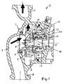
- the housing 1 of a centrifugal pump 2 forms a pump chamber 3, in which an impeller 4 is mounted, which is fixed to one end of a shaft 5, which is driven by an electric motor, not shown.
- the impeller 4 has a coaxial inlet 6, with which the impeller from an inlet channel 7 sucks the liquid, which is connected to a suction nozzle 8.
- the sucked from the inlet 6 liquid is pushed out through impeller blade 9 from the impeller circumference, in a pressure chamber 10 and from there via a pressure channel to a discharge nozzle 11.
- a mechanical seal 12 On the side facing away from the inlet 6 of the impeller 4 sits on the shaft 5, a mechanical seal 12, the surrounded by a mechanical seal space 13 annular.
- the mechanical seal chamber 13 is connected to the pressure chamber 10 via a channel 22, which starts from the pressure chamber 10 and opens into the space 13.
- a circular sealing disc 14 coaxially mounted on the shaft 5 rotatably, so that it rotates with the shaft 5.
- the sealing disc 14 is located on one side on the back of the impeller, or on a coaxially projecting sleeve-shaped nozzle 15 of the impeller 4, and with its other side to a coaxial annular shoulder of the shaft 5, so that it is axially immovable against the shaft 5 is stuck on this.
- the sealing disc 14 has a central opening 16, with which it sits positively on the shaft 5.
- this opening 16 has at least one passage opening which allows the liquid to pass from the mechanical seal chamber 13 via a longitudinal channel 17, in particular a longitudinal groove, to the inlet 6 or the inlet opening of the rotor 4.
- This flow leading from the mechanical seal chamber 13 to the inlet 6 is further improved by the fact that the sealing disk has at least one groove 18 on the side facing away from the rotor, which groove leads from the outer edge of the sealing disk 14 to the passage of the sealing disk.
- two semicircular grooves 18 are arranged near the edge of the disk, with their end in each case merging in a radial region which leads to the passage 19.
- the sealing disc 14 has an inner annular abutment surface 20 in which the mechanical seal 12 abuts and which is interrupted only by the one or more end portions 18a of the grooves 18 of the sealing washer 14, these Nutenend Schemee 18a are arranged approximately radially to the outer ring or partially annular groove area to connect with the opening 16 and the longitudinal channel 17.
- the sliding ring sealing space 13 is connected to the pressure chamber 10 via an annular coaxial opening 19 when the sealing disc 14 is missing.
- the sealing disc 14 closes this opening 19, so that the pressure in the pressure chamber 10 rests against the impeller 4 facing side of the sealing disc 14.
- the sealing disk 14 is pressed by the pressure in the pressure chamber 10 in the direction of the electric motor and thus exerted a pressure on the impeller 4 via the shaft 5 in the same direction. This pressure is opposite to the force that generates the impeller 4 during the suction of the liquid.
Landscapes
- Engineering & Computer Science (AREA)
- Mechanical Engineering (AREA)
- General Engineering & Computer Science (AREA)
- Structures Of Non-Positive Displacement Pumps (AREA)
- Lubrication Of Internal Combustion Engines (AREA)
- Reciprocating Pumps (AREA)
Claims (8)
- Pompe centrifuge (2) pourvue d' un rotor (4) monté sur une extrémité d'un arbre (5) motorisé, une garniture étanche à anneau glissant (12) entourant l'arbre sur le côté du rotor opposé à l'admission (6) du rotor, et la garniture étanche à anneau glissant (12) étant entourée par un espace d'étanchéité (13), balayé par un courant partiel du liquide refoulé, caractérisée en ce que- un disque d'étanchéité rotatif (14) est fixé sur l'arbre (5) dans la direction axiale entre le rotor (4) et la garniture étanche à anneau glissant (12),- le disque d'étanchéité (14) provoque une force axiale opposée à la force de traction axiale du rotor (4), et- le disque d'étanchéité (14) présente, pour le courant partiel de liquide, au moins un passage (19) raccordé à au moins un canal de passage (17), qui mène à l'admission (6) du rotor.
- Pompe centrifuge (2) suivant la revendication 1, caractérisée en ce que le canal de passage (17) est formé par au moins un creux longitudinal, en particulier une gorge longitudinale, dans l'enveloppe de l'arbre (5).
- Pompe centrifuge (2) suivant l'une des revendications 1 et 2, caractérisée en ce que le passage (19) est disposé entre l'arbre (5) et l'ouverture centrale (16) du disque d'étanchéité (14).
- Pompe centrifuge (2) suivant l'une des revendications précédentes, caractérisée en ce que le courant partiel, s'écoulant au travers de l'espace d'étanchéité (13), est en dérivation du côté refoulement de la pompe.
- Pompe centrifuge (2) suivant l'une des revendications précédentes, caractérisée en ce que le côté refoulement de la pompe, en particulier un compartiment de refoulement (10), est étanchéifié en direction de l'espace d'étanchéité par le disque d'étanchéité (14).
- Pompe centrifuge (2) suivant la revendication 5, caractérisée en ce que la cloison (21) entre le côté refoulement, en particulier le compartiment de refoulement (10), et l'espace d'étanchéité (13) présente une ouverture (19) en particulier annulaire, qui est fermée, en particulier remplie, par une zone du disque d'étanchéité (14).
- Pompe centrifuge suivant l'une des revendications précédentes, caractérisée en ce que le disque d'étanchéité (14) présente, sur le côté opposé au rotor (4), au moins une gorge (18) qui mène du bord extérieur du disque d'étanchéité (14) au passage (19) de ce dernier.
- Pompe centrifuge suivant l'une des revendications précédentes, caractérisée en ce que le disque d'étanchéité (14) présente un surface de contact (20), en particulier annulaire, pour la garniture étanche à anneau glissant (12).
Applications Claiming Priority (1)
| Application Number | Priority Date | Filing Date | Title |
|---|---|---|---|
| DE102006004266A DE102006004266A1 (de) | 2006-01-31 | 2006-01-31 | Kreiselpumpe |
Publications (3)
| Publication Number | Publication Date |
|---|---|
| EP1813819A2 EP1813819A2 (fr) | 2007-08-01 |
| EP1813819A3 EP1813819A3 (fr) | 2008-02-27 |
| EP1813819B1 true EP1813819B1 (fr) | 2011-04-27 |
Family
ID=38024250
Family Applications (1)
| Application Number | Title | Priority Date | Filing Date |
|---|---|---|---|
| EP07000756A Active EP1813819B1 (fr) | 2006-01-31 | 2007-01-16 | Pompe centrifuge |
Country Status (3)
| Country | Link |
|---|---|
| EP (1) | EP1813819B1 (fr) |
| AT (1) | ATE507395T1 (fr) |
| DE (2) | DE102006004266A1 (fr) |
Families Citing this family (3)
| Publication number | Priority date | Publication date | Assignee | Title |
|---|---|---|---|---|
| CN113202809A (zh) * | 2021-05-22 | 2021-08-03 | 中国计量大学 | 一种不会对外泄漏泵内输送液体分子的全密封型水泵的结构 |
| CN113357186A (zh) * | 2021-05-22 | 2021-09-07 | 中国计量大学 | 一种全密封型水泵的结构 |
| CN113236599A (zh) * | 2021-05-22 | 2021-08-10 | 中国计量大学 | 不外泄泵内被输送液体分子的且扬程全由电机决定的化工泵结构 |
Family Cites Families (10)
| Publication number | Priority date | Publication date | Assignee | Title |
|---|---|---|---|---|
| GB1120231A (en) * | 1964-07-08 | 1968-07-17 | Worthington Simpson | Rotary pumps |
| DE2914652A1 (de) * | 1979-04-11 | 1980-10-30 | Kloeckner Humboldt Deutz Ag | Verstellbares mikrofilmkartenlesegeraet |
| DE3432662C2 (de) * | 1984-09-05 | 1986-10-16 | Tanabe Machinery Co., Ltd., Tokio/Tokyo | Vorrichtung zum Erfassen eines Sollmaßes eines Schachtelzuschnittes für eine Schachtelherstellungsmaschine |
| DE3438662C2 (de) * | 1984-10-22 | 1997-01-30 | Sihi Gmbh & Co Kg | Kreiselpumpe für heiße Medien |
| DE8601166U1 (de) * | 1986-01-18 | 1986-02-27 | Sihi Gmbh & Co Kg, 2210 Itzehoe | Pumpe zur Förderung von Heißwasser |
| DE8627766U1 (de) * | 1986-10-17 | 1988-02-11 | Sihi Gmbh & Co Kg, 2210 Itzehoe | Kreiselpumpe |
| DE3825799A1 (de) * | 1988-07-29 | 1990-02-01 | Messer Griesheim Gmbh | Kreiselpumpe |
| DE3914652A1 (de) * | 1989-05-03 | 1990-11-08 | Sihi Gmbh & Co Kg | Kreiselpumpe |
| CA2015777C (fr) * | 1990-04-30 | 1993-10-12 | Lynn P. Tessier | Pompe centrifuge |
| GB2290113B (en) * | 1994-05-31 | 1998-07-15 | Ingersoll Dresser Pump Co | Centrifugal pump |
-
2006
- 2006-01-31 DE DE102006004266A patent/DE102006004266A1/de not_active Withdrawn
-
2007
- 2007-01-16 DE DE502007007033T patent/DE502007007033D1/de active Active
- 2007-01-16 EP EP07000756A patent/EP1813819B1/fr active Active
- 2007-01-16 AT AT07000756T patent/ATE507395T1/de active
Also Published As
| Publication number | Publication date |
|---|---|
| DE102006004266A1 (de) | 2007-08-02 |
| DE502007007033D1 (de) | 2011-06-09 |
| ATE507395T1 (de) | 2011-05-15 |
| EP1813819A2 (fr) | 2007-08-01 |
| EP1813819A3 (fr) | 2008-02-27 |
Similar Documents
| Publication | Publication Date | Title |
|---|---|---|
| WO2017162775A1 (fr) | Pompe à entraînement magnétique | |
| DE10012181A1 (de) | Kreiselpumpe mit Noppen-Laufrad und Noppen-Laufrad hierfür | |
| EP2864640B1 (fr) | Pompe centrifuge de moteur pourvue d'une garniture étanche à anneau glissant | |
| EP1813819B1 (fr) | Pompe centrifuge | |
| DE102007032228A1 (de) | Selbstansaugende Pumpenaggregation | |
| EP2348219B1 (fr) | Pompe de liquide de refroidissement | |
| WO2006066692A1 (fr) | Ensemble constitue d'un arbre sur lequel un joint a anneaux glissants est monte | |
| DE102007020218A1 (de) | Förderpumpe | |
| DE4415566C2 (de) | Seitenkanalpumpe | |
| DE10062451A1 (de) | Förderpumpe | |
| DE102007025402B4 (de) | Pumpe für ein Haushaltsgerät | |
| DE102015212653B4 (de) | Haushaltsgerät | |
| WO2020078621A1 (fr) | Pompe à liquide de refroidissement à enfichage comprenant une rondelle d'étanchéité servant à réduire au minimum un jeu d'étanchéité | |
| EP1327781B1 (fr) | Pompe centrifuge auto-amorçante | |
| EP3090185B1 (fr) | Pompe centrifuge à dispositif de coupe | |
| DE10019819A1 (de) | Pumpe, insbesondere Umwälzpumpe für Haushaltsmaschinen wie Geschirrspülmaschinen | |
| DE102015212654B4 (de) | Haushaltsgerät | |
| WO1999039105A1 (fr) | Roue mobile de pompe centrifuge, de structure radiale | |
| DE102010010593B4 (de) | Kreiselpumpe | |
| DE2125040B2 (de) | Kreiselpumpe | |
| DE102012222336B4 (de) | Strömungsmaschine | |
| DE10307883A1 (de) | Kreiselpumpe | |
| DE112007002363T5 (de) | Pneumatischer Flügelzellenmotor | |
| EP3728860B1 (fr) | Compresseurs à canal latéral, en particulier compresseurs d'air secondaires pour un moteur à combustion interne | |
| EP1369977B1 (fr) | Moteur électrique pour entraînement d'une pompe de liquide |
Legal Events
| Date | Code | Title | Description |
|---|---|---|---|
| PUAI | Public reference made under article 153(3) epc to a published international application that has entered the european phase |
Free format text: ORIGINAL CODE: 0009012 |
|
| AK | Designated contracting states |
Kind code of ref document: A2 Designated state(s): AT BE BG CH CY CZ DE DK EE ES FI FR GB GR HU IE IS IT LI LT LU LV MC NL PL PT RO SE SI SK TR |
|
| AX | Request for extension of the european patent |
Extension state: AL BA HR MK YU |
|
| PUAL | Search report despatched |
Free format text: ORIGINAL CODE: 0009013 |
|
| AK | Designated contracting states |
Kind code of ref document: A3 Designated state(s): AT BE BG CH CY CZ DE DK EE ES FI FR GB GR HU IE IS IT LI LT LU LV MC NL PL PT RO SE SI SK TR |
|
| AX | Request for extension of the european patent |
Extension state: AL BA HR MK YU |
|
| 17P | Request for examination filed |
Effective date: 20080403 |
|
| 17Q | First examination report despatched |
Effective date: 20080609 |
|
| AKX | Designation fees paid |
Designated state(s): AT BE BG CH CY CZ DE DK EE ES FI FR GB GR HU IE IS IT LI LT LU LV MC NL PL PT RO SE SI SK TR |
|
| GRAP | Despatch of communication of intention to grant a patent |
Free format text: ORIGINAL CODE: EPIDOSNIGR1 |
|
| GRAS | Grant fee paid |
Free format text: ORIGINAL CODE: EPIDOSNIGR3 |
|
| GRAA | (expected) grant |
Free format text: ORIGINAL CODE: 0009210 |
|
| RAP1 | Party data changed (applicant data changed or rights of an application transferred) |
Owner name: WILO SE |
|
| AK | Designated contracting states |
Kind code of ref document: B1 Designated state(s): AT BE BG CH CY CZ DE DK EE ES FI FR GB GR HU IE IS IT LI LT LU LV MC NL PL PT RO SE SI SK TR |
|
| REG | Reference to a national code |
Ref country code: GB Ref legal event code: FG4D Free format text: NOT ENGLISH |
|
| REG | Reference to a national code |
Ref country code: CH Ref legal event code: EP |
|
| REG | Reference to a national code |
Ref country code: IE Ref legal event code: FG4D Free format text: LANGUAGE OF EP DOCUMENT: GERMAN |
|
| REF | Corresponds to: |
Ref document number: 502007007033 Country of ref document: DE Date of ref document: 20110609 Kind code of ref document: P |
|
| REG | Reference to a national code |
Ref country code: DE Ref legal event code: R096 Ref document number: 502007007033 Country of ref document: DE Effective date: 20110609 |
|
| REG | Reference to a national code |
Ref country code: NL Ref legal event code: VDEP Effective date: 20110427 |
|
| LTIE | Lt: invalidation of european patent or patent extension |
Effective date: 20110427 |
|
| PG25 | Lapsed in a contracting state [announced via postgrant information from national office to epo] |
Ref country code: SE Free format text: LAPSE BECAUSE OF FAILURE TO SUBMIT A TRANSLATION OF THE DESCRIPTION OR TO PAY THE FEE WITHIN THE PRESCRIBED TIME-LIMIT Effective date: 20110427 Ref country code: PT Free format text: LAPSE BECAUSE OF FAILURE TO SUBMIT A TRANSLATION OF THE DESCRIPTION OR TO PAY THE FEE WITHIN THE PRESCRIBED TIME-LIMIT Effective date: 20110829 Ref country code: LT Free format text: LAPSE BECAUSE OF FAILURE TO SUBMIT A TRANSLATION OF THE DESCRIPTION OR TO PAY THE FEE WITHIN THE PRESCRIBED TIME-LIMIT Effective date: 20110427 |
|
| REG | Reference to a national code |
Ref country code: IE Ref legal event code: FD4D |
|
| PG25 | Lapsed in a contracting state [announced via postgrant information from national office to epo] |
Ref country code: IS Free format text: LAPSE BECAUSE OF FAILURE TO SUBMIT A TRANSLATION OF THE DESCRIPTION OR TO PAY THE FEE WITHIN THE PRESCRIBED TIME-LIMIT Effective date: 20110827 Ref country code: ES Free format text: LAPSE BECAUSE OF FAILURE TO SUBMIT A TRANSLATION OF THE DESCRIPTION OR TO PAY THE FEE WITHIN THE PRESCRIBED TIME-LIMIT Effective date: 20110807 Ref country code: SI Free format text: LAPSE BECAUSE OF FAILURE TO SUBMIT A TRANSLATION OF THE DESCRIPTION OR TO PAY THE FEE WITHIN THE PRESCRIBED TIME-LIMIT Effective date: 20110427 Ref country code: LV Free format text: LAPSE BECAUSE OF FAILURE TO SUBMIT A TRANSLATION OF THE DESCRIPTION OR TO PAY THE FEE WITHIN THE PRESCRIBED TIME-LIMIT Effective date: 20110427 Ref country code: FI Free format text: LAPSE BECAUSE OF FAILURE TO SUBMIT A TRANSLATION OF THE DESCRIPTION OR TO PAY THE FEE WITHIN THE PRESCRIBED TIME-LIMIT Effective date: 20110427 Ref country code: CY Free format text: LAPSE BECAUSE OF FAILURE TO SUBMIT A TRANSLATION OF THE DESCRIPTION OR TO PAY THE FEE WITHIN THE PRESCRIBED TIME-LIMIT Effective date: 20110427 Ref country code: GR Free format text: LAPSE BECAUSE OF FAILURE TO SUBMIT A TRANSLATION OF THE DESCRIPTION OR TO PAY THE FEE WITHIN THE PRESCRIBED TIME-LIMIT Effective date: 20110728 |
|
| PG25 | Lapsed in a contracting state [announced via postgrant information from national office to epo] |
Ref country code: NL Free format text: LAPSE BECAUSE OF FAILURE TO SUBMIT A TRANSLATION OF THE DESCRIPTION OR TO PAY THE FEE WITHIN THE PRESCRIBED TIME-LIMIT Effective date: 20110427 |
|
| PG25 | Lapsed in a contracting state [announced via postgrant information from national office to epo] |
Ref country code: CZ Free format text: LAPSE BECAUSE OF FAILURE TO SUBMIT A TRANSLATION OF THE DESCRIPTION OR TO PAY THE FEE WITHIN THE PRESCRIBED TIME-LIMIT Effective date: 20110427 Ref country code: EE Free format text: LAPSE BECAUSE OF FAILURE TO SUBMIT A TRANSLATION OF THE DESCRIPTION OR TO PAY THE FEE WITHIN THE PRESCRIBED TIME-LIMIT Effective date: 20110427 Ref country code: IE Free format text: LAPSE BECAUSE OF FAILURE TO SUBMIT A TRANSLATION OF THE DESCRIPTION OR TO PAY THE FEE WITHIN THE PRESCRIBED TIME-LIMIT Effective date: 20110427 |
|
| PG25 | Lapsed in a contracting state [announced via postgrant information from national office to epo] |
Ref country code: PL Free format text: LAPSE BECAUSE OF FAILURE TO SUBMIT A TRANSLATION OF THE DESCRIPTION OR TO PAY THE FEE WITHIN THE PRESCRIBED TIME-LIMIT Effective date: 20110427 Ref country code: SK Free format text: LAPSE BECAUSE OF FAILURE TO SUBMIT A TRANSLATION OF THE DESCRIPTION OR TO PAY THE FEE WITHIN THE PRESCRIBED TIME-LIMIT Effective date: 20110427 Ref country code: RO Free format text: LAPSE BECAUSE OF FAILURE TO SUBMIT A TRANSLATION OF THE DESCRIPTION OR TO PAY THE FEE WITHIN THE PRESCRIBED TIME-LIMIT Effective date: 20110427 Ref country code: DK Free format text: LAPSE BECAUSE OF FAILURE TO SUBMIT A TRANSLATION OF THE DESCRIPTION OR TO PAY THE FEE WITHIN THE PRESCRIBED TIME-LIMIT Effective date: 20110427 |
|
| PLBE | No opposition filed within time limit |
Free format text: ORIGINAL CODE: 0009261 |
|
| STAA | Information on the status of an ep patent application or granted ep patent |
Free format text: STATUS: NO OPPOSITION FILED WITHIN TIME LIMIT |
|
| 26N | No opposition filed |
Effective date: 20120130 |
|
| REG | Reference to a national code |
Ref country code: DE Ref legal event code: R097 Ref document number: 502007007033 Country of ref document: DE Effective date: 20120130 |
|
| BERE | Be: lapsed |
Owner name: WILO SE Effective date: 20120131 |
|
| PG25 | Lapsed in a contracting state [announced via postgrant information from national office to epo] |
Ref country code: MC Free format text: LAPSE BECAUSE OF NON-PAYMENT OF DUE FEES Effective date: 20120131 |
|
| REG | Reference to a national code |
Ref country code: CH Ref legal event code: PL |
|
| PG25 | Lapsed in a contracting state [announced via postgrant information from national office to epo] |
Ref country code: CH Free format text: LAPSE BECAUSE OF NON-PAYMENT OF DUE FEES Effective date: 20120131 Ref country code: LI Free format text: LAPSE BECAUSE OF NON-PAYMENT OF DUE FEES Effective date: 20120131 |
|
| PG25 | Lapsed in a contracting state [announced via postgrant information from national office to epo] |
Ref country code: BE Free format text: LAPSE BECAUSE OF NON-PAYMENT OF DUE FEES Effective date: 20120131 |
|
| REG | Reference to a national code |
Ref country code: AT Ref legal event code: MM01 Ref document number: 507395 Country of ref document: AT Kind code of ref document: T Effective date: 20120116 |
|
| PG25 | Lapsed in a contracting state [announced via postgrant information from national office to epo] |
Ref country code: BG Free format text: LAPSE BECAUSE OF FAILURE TO SUBMIT A TRANSLATION OF THE DESCRIPTION OR TO PAY THE FEE WITHIN THE PRESCRIBED TIME-LIMIT Effective date: 20110727 Ref country code: AT Free format text: LAPSE BECAUSE OF NON-PAYMENT OF DUE FEES Effective date: 20120116 |
|
| PG25 | Lapsed in a contracting state [announced via postgrant information from national office to epo] |
Ref country code: TR Free format text: LAPSE BECAUSE OF FAILURE TO SUBMIT A TRANSLATION OF THE DESCRIPTION OR TO PAY THE FEE WITHIN THE PRESCRIBED TIME-LIMIT Effective date: 20110427 |
|
| PG25 | Lapsed in a contracting state [announced via postgrant information from national office to epo] |
Ref country code: LU Free format text: LAPSE BECAUSE OF NON-PAYMENT OF DUE FEES Effective date: 20120116 |
|
| PG25 | Lapsed in a contracting state [announced via postgrant information from national office to epo] |
Ref country code: HU Free format text: LAPSE BECAUSE OF FAILURE TO SUBMIT A TRANSLATION OF THE DESCRIPTION OR TO PAY THE FEE WITHIN THE PRESCRIBED TIME-LIMIT Effective date: 20070116 |
|
| PGFP | Annual fee paid to national office [announced via postgrant information from national office to epo] |
Ref country code: GB Payment date: 20150114 Year of fee payment: 9 |
|
| REG | Reference to a national code |
Ref country code: FR Ref legal event code: PLFP Year of fee payment: 10 |
|
| GBPC | Gb: european patent ceased through non-payment of renewal fee |
Effective date: 20160116 |
|
| PG25 | Lapsed in a contracting state [announced via postgrant information from national office to epo] |
Ref country code: GB Free format text: LAPSE BECAUSE OF NON-PAYMENT OF DUE FEES Effective date: 20160116 |
|
| REG | Reference to a national code |
Ref country code: FR Ref legal event code: PLFP Year of fee payment: 11 |
|
| REG | Reference to a national code |
Ref country code: FR Ref legal event code: PLFP Year of fee payment: 12 |
|
| P01 | Opt-out of the competence of the unified patent court (upc) registered |
Effective date: 20230615 |
|
| PGFP | Annual fee paid to national office [announced via postgrant information from national office to epo] |
Ref country code: FR Payment date: 20231219 Year of fee payment: 18 |
|
| PGFP | Annual fee paid to national office [announced via postgrant information from national office to epo] |
Ref country code: IT Payment date: 20240102 Year of fee payment: 18 |
|
| REG | Reference to a national code |
Ref country code: DE Ref legal event code: R084 Ref document number: 502007007033 Country of ref document: DE |
|
| PG25 | Lapsed in a contracting state [announced via postgrant information from national office to epo] |
Ref country code: FR Free format text: LAPSE BECAUSE OF NON-PAYMENT OF DUE FEES Effective date: 20250131 |
|
| PG25 | Lapsed in a contracting state [announced via postgrant information from national office to epo] |
Ref country code: IT Free format text: LAPSE BECAUSE OF NON-PAYMENT OF DUE FEES Effective date: 20250116 |
|
| PGFP | Annual fee paid to national office [announced via postgrant information from national office to epo] |
Ref country code: DE Payment date: 20251217 Year of fee payment: 20 |