EP1813850A2 - Dispositif de connexion pour tuyaux en plastique - Google Patents
Dispositif de connexion pour tuyaux en plastique Download PDFInfo
- Publication number
- EP1813850A2 EP1813850A2 EP05380272A EP05380272A EP1813850A2 EP 1813850 A2 EP1813850 A2 EP 1813850A2 EP 05380272 A EP05380272 A EP 05380272A EP 05380272 A EP05380272 A EP 05380272A EP 1813850 A2 EP1813850 A2 EP 1813850A2
- Authority
- EP
- European Patent Office
- Prior art keywords
- flanges
- connection
- pipe
- pipes
- coupling
- Prior art date
- Legal status (The legal status is an assumption and is not a legal conclusion. Google has not performed a legal analysis and makes no representation as to the accuracy of the status listed.)
- Withdrawn
Links
Images

Classifications
-
- F—MECHANICAL ENGINEERING; LIGHTING; HEATING; WEAPONS; BLASTING
- F16—ENGINEERING ELEMENTS AND UNITS; GENERAL MEASURES FOR PRODUCING AND MAINTAINING EFFECTIVE FUNCTIONING OF MACHINES OR INSTALLATIONS; THERMAL INSULATION IN GENERAL
- F16L—PIPES; JOINTS OR FITTINGS FOR PIPES; SUPPORTS FOR PIPES, CABLES OR PROTECTIVE TUBING; MEANS FOR THERMAL INSULATION IN GENERAL
- F16L33/00—Arrangements for connecting hoses to rigid members; Rigid hose-connectors, i.e. single members engaging both hoses
- F16L33/22—Arrangements for connecting hoses to rigid members; Rigid hose-connectors, i.e. single members engaging both hoses with means not mentioned in the preceding groups for gripping the hose between inner and outer parts
- F16L33/227—Arrangements for connecting hoses to rigid members; Rigid hose-connectors, i.e. single members engaging both hoses with means not mentioned in the preceding groups for gripping the hose between inner and outer parts the hose being introduced into or onto the connecting member and automatically locked
-
- F—MECHANICAL ENGINEERING; LIGHTING; HEATING; WEAPONS; BLASTING
- F16—ENGINEERING ELEMENTS AND UNITS; GENERAL MEASURES FOR PRODUCING AND MAINTAINING EFFECTIVE FUNCTIONING OF MACHINES OR INSTALLATIONS; THERMAL INSULATION IN GENERAL
- F16L—PIPES; JOINTS OR FITTINGS FOR PIPES; SUPPORTS FOR PIPES, CABLES OR PROTECTIVE TUBING; MEANS FOR THERMAL INSULATION IN GENERAL
- F16L37/00—Couplings of the quick-acting type
- F16L37/08—Couplings of the quick-acting type in which the connection between abutting or axially overlapping ends is maintained by locking members
- F16L37/084—Couplings of the quick-acting type in which the connection between abutting or axially overlapping ends is maintained by locking members combined with automatic locking
- F16L37/091—Couplings of the quick-acting type in which the connection between abutting or axially overlapping ends is maintained by locking members combined with automatic locking by means of a ring provided with teeth or fingers
Definitions
- the present invention relates to a connection device that is specially designed for plastic pipes, with which it is possible to carry out the connection, change of direction, etc., of pipes through which fluids flow under pressure in an extremely quick, simple and efficient manner.
- the object of the invention is to achieve a perfect coupling between plastic pipes that is absolutely watertight and where the assembly of the pipe with the fitting is performed quickly and simply, without the need to use any kind of mechanical tool.
- the device is particularly suitable for use with reticulated polyethylene pipes and multilayer pipes, but it is equally valid for any other type of plastic pipe.
- One device that enables said connection to be made consists of a metal body and compression couplings that are also made of metal. This technique is based on the pressure applied by the coupling to the pipe, which ensures that the latter is thus secured to the fitting.
- the pipe is cold countersunk, clamped over the fitting and the coupling is inserted into the pipe by machines that apply a rear axial compression and pressing force thereto.
- fittings consist of a metal or plastic body with pre-assembled metal compression couplings on the body of said fittings.
- the basis for the coupling technique used between these fittings and reticulated polyethylene or multilayer pipes is similar to the previous technique: the coupling presses the pipe against the body of the fitting.
- the assembly is performed using special tools that apply a radial compression force to the metal coupling. It is necessary to point out that, in the case of the fittings used in the connection of multilayer pipes, the assembly is sealed by means of rubber O-rings between the teat of the fitting and the inner wall of the pipe.
- the device proposed by the invention solves the problem of the previous technology that is inherent in the fact that it is complicated to assemble and requires the use of special tools, so that, as has been mentioned above, the assembly of the pipe and the device may be performed quickly, simply and without the need for any type of mechanical tool.
- the device being recommended has a tubular body which constitutes the connector itself and can be rectilinear, L-shaped, T-shaped, etc., but in all cases includes perimeter slots for the installation of respective gaskets on at least one of its branches, upon which radial pressure is to be applied by the plastic pipe, the inner diameter of which is adapted to the outer diameter of the aforementioned tubular body.
- said branch includes a number of radial flanges inside the slots, next to the gaskets, that enable the connection by bayonet or pressure of a metal coupling that will be pre-assembled on the tubular body and which forms a cylindrical housing into which to insert the corresponding end of the plastic pipe, but with the special feature that said metal coupling includes a number of slanting inner tabs, formed at the mouth thereof or at any other point along the cylindrical body and duly orientated in order to favour the penetration of the pipe into said housing and so that they are driven into the wall thereof when the pipe is liable to disconnect from the tubular body.
- the outer diameter of said connection is not necessary for the outer diameter of said connection to be any greater than the outer diameter of the pipe at the point of connection, which makes it considerably easier to embed installations in walls or suchlike, without the need to considerably widen the channels in the walls in areas where there are connections, as is usually the case.
- the assembly time is substantially reduced and it is not necessary to use mechanical tools, as the device enables pipes to be assembled manually by simply aligning the device and applying a small amount of axial pressure thereto.
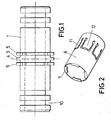
- the device proposed by the invention is formed from a tubular body (1), which in the chosen example of a practical embodiment takes a rectilinear form, so that the device is to coaxially connect two sections of pipe (2) but which, as has been mentioned above, could be L-shaped, T-shaped, cross-shaped, etc., according to the type of connection to be made thereby.
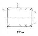
- a small central perimeter partition (3) is established on the body (1) corresponding to its plane of symmetry (4), and on either side thereof at least two pairs of radial and equiangularly-positioned flanges (5) are established for the axial securing of a coupling (6), with one of its mouths, which will be its inner mouth, having flanges (7) that are orthogonal or slanting inwards towards the axis of the coupling, complementary to the aforementioned flanges (5), in order to enable the coupling (6) to be connected by bayonet or pressure to the body (1).
- the body (1) can be made of metal or plastic, but the coupling (6) will always be metal and elastic in nature, in order to secure the pipe (2), as will be seen below.
- the couplings (6) can originally be pre-assembled on the body (1), as shown on the right of figure 3, forming a tubular cylindrical housing (8) into which the corresponding section of pipe (2) can be inserted using pressure, which is completely sealed against the body (1) by O-rings (9) positioned in annular channels (10) thereof, said pipe also being axially secured against the effects of the inner pressure thereof which could bring about its axial disconnection, the coupling (6) having U-shaped die cuts (11) that forms flanges (12) slanting inwards towards the inner end of the coupling (6) so that said flanges (12) are easily deformed when the pipe (2) is inserted, thus aiding the connection thereof, but tend to be driven into the wall of the pipe in the event of any force being applied in the opposite direction, that is, should there be any force that is liable to disconnect the pipe (2) from the body (1).
- the coupling (6) can include flanges (12') that are a prolongation of its free edge opposite the edge where the flanges (7) are situated.
- these flanges (12') will also be slanting inwards towards the inner end of the coupling (6), by the folding thereof, thus achieving the same interlocking effects as in the previous case.
Landscapes
- Engineering & Computer Science (AREA)
- General Engineering & Computer Science (AREA)
- Mechanical Engineering (AREA)
- Quick-Acting Or Multi-Walled Pipe Joints (AREA)
Applications Claiming Priority (1)
| Application Number | Priority Date | Filing Date | Title |
|---|---|---|---|
| ES200502489 | 2005-11-14 |
Publications (2)
| Publication Number | Publication Date |
|---|---|
| EP1813850A2 true EP1813850A2 (fr) | 2007-08-01 |
| EP1813850A3 EP1813850A3 (fr) | 2007-08-15 |
Family
ID=38145785
Family Applications (1)
| Application Number | Title | Priority Date | Filing Date |
|---|---|---|---|
| EP05380272A Withdrawn EP1813850A3 (fr) | 2005-11-14 | 2005-12-20 | Dispositif de connexion pour tuyaux en plastique |
Country Status (1)
| Country | Link |
|---|---|
| EP (1) | EP1813850A3 (fr) |
Cited By (4)
| Publication number | Priority date | Publication date | Assignee | Title |
|---|---|---|---|---|
| WO2009108963A3 (fr) * | 2008-02-26 | 2009-11-12 | Hendrik Jakobus Van Wyk | Raccord de tuyau |
| EP2249072A1 (fr) * | 2009-04-28 | 2010-11-10 | KE-KELIT Kunststoffwerk Gesellschaft m.b.H. | Dispositif de raccordement pour un tuyau en plastique sur un raccord de connexion |
| AU2010345700B2 (en) * | 2010-02-10 | 2015-08-20 | Ke-Kelit Kunststoffwerk Gesellschaft M.B.H. | Device for connecting a plastic tube to a connection nipple |
| EP2246606A3 (fr) * | 2009-04-28 | 2016-09-21 | KE KELIT Kunststoffwerk Gesellschaft m.b.H. | Dispositif de raccordement pour un tuyau en plastique sur un raccord fileté |
Family Cites Families (4)
| Publication number | Priority date | Publication date | Assignee | Title |
|---|---|---|---|---|
| US3003792A (en) * | 1959-04-14 | 1961-10-10 | Robert A Gilmour | Flexible hose coupler with rotational cam |
| DE19741641C2 (de) * | 1997-09-22 | 2000-11-23 | Wavin Bv | Anschlußvorrichtung für ein Rohr- oder Schlauchteil |
| JP4068563B2 (ja) * | 2001-11-28 | 2008-03-26 | フリアテツク・アクテイエンゲゼルシヤフト | 差込継手 |
| GB0311760D0 (en) * | 2003-05-22 | 2003-06-25 | Yorkshire Fittings Ltd | Tube coupling device |
-
2005
- 2005-12-20 EP EP05380272A patent/EP1813850A3/fr not_active Withdrawn
Cited By (4)
| Publication number | Priority date | Publication date | Assignee | Title |
|---|---|---|---|---|
| WO2009108963A3 (fr) * | 2008-02-26 | 2009-11-12 | Hendrik Jakobus Van Wyk | Raccord de tuyau |
| EP2249072A1 (fr) * | 2009-04-28 | 2010-11-10 | KE-KELIT Kunststoffwerk Gesellschaft m.b.H. | Dispositif de raccordement pour un tuyau en plastique sur un raccord de connexion |
| EP2246606A3 (fr) * | 2009-04-28 | 2016-09-21 | KE KELIT Kunststoffwerk Gesellschaft m.b.H. | Dispositif de raccordement pour un tuyau en plastique sur un raccord fileté |
| AU2010345700B2 (en) * | 2010-02-10 | 2015-08-20 | Ke-Kelit Kunststoffwerk Gesellschaft M.B.H. | Device for connecting a plastic tube to a connection nipple |
Also Published As
| Publication number | Publication date |
|---|---|
| EP1813850A3 (fr) | 2007-08-15 |
Similar Documents
| Publication | Publication Date | Title |
|---|---|---|
| AU2023201575B2 (en) | Pipe connection fitting | |
| EP2220417B1 (fr) | Dispositif permettant de connecter deux objets rigides | |
| CA2939349C (fr) | Ensemble a connexion par poussee de type coque a grappins | |
| EP1716358B1 (fr) | Ensemble connecteur pour elements males et femelles | |
| US20100171302A1 (en) | Push-twist connector | |
| EP2221520B1 (fr) | Raccord de tuyau | |
| JP2024012603A (ja) | 管状要素への連結用継手、配管連結体、および管状要素への継手連結方法 | |
| EP3837465A1 (fr) | Raccord tubulaire | |
| US20110204624A1 (en) | Universal connection socket | |
| EP2314904B1 (fr) | Retenue de tube | |
| PL199625B1 (pl) | Szybkozłącze dla rur | |
| US8555480B2 (en) | Two part coupling connected by a clip | |
| CN103582776A (zh) | 连接器装置 | |
| US20140021717A1 (en) | Pipe connector assembly | |
| US8782872B2 (en) | Multi-piece piping connector using grooves and method of connecting pipe using the same | |
| WO2016014767A1 (fr) | Raccord de tube universel pouvant s'adapter à des tubes de différentes tailles | |
| EP1813850A2 (fr) | Dispositif de connexion pour tuyaux en plastique | |
| US20030197378A1 (en) | Sealing compression ferrule for plumbing connection fitting | |
| US10648601B2 (en) | Quick connect system for a fluid coupling | |
| CN115468052A (zh) | 用于连接流体输送管的接头和方法 | |
| KR100928164B1 (ko) | 멀티 주철관 연결장치 | |
| CN109822506B (zh) | 用于挤压工具的活动钳 | |
| WO2003085311A1 (fr) | Nouveau procede utilise pour le raccordement de parties tubulaires en cuivre | |
| EP0533638A2 (fr) | Raccord rapide | |
| AU2006303863A1 (en) | Assembling pipe fitting components with crimped ferrule clamping a pipe to the fitting |
Legal Events
| Date | Code | Title | Description |
|---|---|---|---|
| PUAI | Public reference made under article 153(3) epc to a published international application that has entered the european phase |
Free format text: ORIGINAL CODE: 0009012 |
|
| PUAL | Search report despatched |
Free format text: ORIGINAL CODE: 0009013 |
|
| AK | Designated contracting states |
Kind code of ref document: A2 Designated state(s): AT BE BG CH CY CZ DE DK EE ES FI FR GB GR HU IE IS IT LI LT LU LV MC NL PL PT RO SE SI SK TR |
|
| AX | Request for extension of the european patent |
Extension state: AL BA HR MK YU |
|
| AK | Designated contracting states |
Kind code of ref document: A3 Designated state(s): AT BE BG CH CY CZ DE DK EE ES FI FR GB GR HU IE IS IT LI LT LU LV MC NL PL PT RO SE SI SK TR |
|
| AX | Request for extension of the european patent |
Extension state: AL BA HR MK YU |
|
| RIC1 | Information provided on ipc code assigned before grant |
Ipc: F16L 33/22 20060101AFI20070710BHEP |
|
| STAA | Information on the status of an ep patent application or granted ep patent |
Free format text: STATUS: THE APPLICATION HAS BEEN WITHDRAWN |
|
| 18W | Application withdrawn |
Effective date: 20080204 |