EP1813857A1 - Source de lumière - Google Patents
Source de lumière Download PDFInfo
- Publication number
- EP1813857A1 EP1813857A1 EP06405039A EP06405039A EP1813857A1 EP 1813857 A1 EP1813857 A1 EP 1813857A1 EP 06405039 A EP06405039 A EP 06405039A EP 06405039 A EP06405039 A EP 06405039A EP 1813857 A1 EP1813857 A1 EP 1813857A1
- Authority
- EP
- European Patent Office
- Prior art keywords
- light source
- light
- led
- optically transparent
- rod
- Prior art date
- Legal status (The legal status is an assumption and is not a legal conclusion. Google has not performed a legal analysis and makes no representation as to the accuracy of the status listed.)
- Withdrawn
Links
- 239000012780 transparent material Substances 0.000 claims abstract description 16
- 238000000034 method Methods 0.000 claims abstract description 12
- 238000004519 manufacturing process Methods 0.000 claims abstract description 6
- 239000000463 material Substances 0.000 claims description 19
- 239000004020 conductor Substances 0.000 claims description 13
- 239000007788 liquid Substances 0.000 claims description 8
- 230000001681 protective effect Effects 0.000 claims description 7
- 239000000969 carrier Substances 0.000 claims description 6
- 238000009826 distribution Methods 0.000 description 18
- 238000005286 illumination Methods 0.000 description 15
- 230000000875 corresponding effect Effects 0.000 description 11
- 229920003229 poly(methyl methacrylate) Polymers 0.000 description 10
- 239000004926 polymethyl methacrylate Substances 0.000 description 10
- 230000003287 optical effect Effects 0.000 description 8
- 238000005452 bending Methods 0.000 description 7
- 230000007613 environmental effect Effects 0.000 description 6
- 229920001296 polysiloxane Polymers 0.000 description 6
- 238000001816 cooling Methods 0.000 description 5
- 239000011521 glass Substances 0.000 description 5
- 239000004417 polycarbonate Substances 0.000 description 5
- 229920000515 polycarbonate Polymers 0.000 description 5
- RYGMFSIKBFXOCR-UHFFFAOYSA-N Copper Chemical compound [Cu] RYGMFSIKBFXOCR-UHFFFAOYSA-N 0.000 description 4
- 230000008901 benefit Effects 0.000 description 4
- 229910052802 copper Inorganic materials 0.000 description 4
- 239000010949 copper Substances 0.000 description 4
- 229920003023 plastic Polymers 0.000 description 4
- 239000004033 plastic Substances 0.000 description 4
- 239000007787 solid Substances 0.000 description 4
- 238000000576 coating method Methods 0.000 description 3
- 230000000694 effects Effects 0.000 description 3
- 239000013013 elastic material Substances 0.000 description 3
- 230000005855 radiation Effects 0.000 description 3
- 230000008859 change Effects 0.000 description 2
- 239000011248 coating agent Substances 0.000 description 2
- 150000001875 compounds Chemical class 0.000 description 2
- 238000010276 construction Methods 0.000 description 2
- 230000004313 glare Effects 0.000 description 2
- 229910052751 metal Inorganic materials 0.000 description 2
- 239000002184 metal Substances 0.000 description 2
- 230000008569 process Effects 0.000 description 2
- 238000007493 shaping process Methods 0.000 description 2
- 241001136792 Alle Species 0.000 description 1
- 229910000906 Bronze Inorganic materials 0.000 description 1
- 241001523162 Helle Species 0.000 description 1
- 229910000831 Steel Inorganic materials 0.000 description 1
- 239000000853 adhesive Substances 0.000 description 1
- 230000001070 adhesive effect Effects 0.000 description 1
- 229910052782 aluminium Inorganic materials 0.000 description 1
- XAGFODPZIPBFFR-UHFFFAOYSA-N aluminium Chemical compound [Al] XAGFODPZIPBFFR-UHFFFAOYSA-N 0.000 description 1
- 239000010974 bronze Substances 0.000 description 1
- 239000012876 carrier material Substances 0.000 description 1
- 239000003086 colorant Substances 0.000 description 1
- KUNSUQLRTQLHQQ-UHFFFAOYSA-N copper tin Chemical compound [Cu].[Sn] KUNSUQLRTQLHQQ-UHFFFAOYSA-N 0.000 description 1
- 230000001419 dependent effect Effects 0.000 description 1
- 239000008157 edible vegetable oil Substances 0.000 description 1
- 230000005670 electromagnetic radiation Effects 0.000 description 1
- 239000011888 foil Substances 0.000 description 1
- 230000009477 glass transition Effects 0.000 description 1
- 238000010438 heat treatment Methods 0.000 description 1
- 238000007654 immersion Methods 0.000 description 1
- 238000009434 installation Methods 0.000 description 1
- 239000010705 motor oil Substances 0.000 description 1
- 230000007935 neutral effect Effects 0.000 description 1
- 238000009304 pastoral farming Methods 0.000 description 1
- 230000001902 propagating effect Effects 0.000 description 1
- 238000000926 separation method Methods 0.000 description 1
- 229910000679 solder Inorganic materials 0.000 description 1
- 238000005476 soldering Methods 0.000 description 1
- 230000006641 stabilisation Effects 0.000 description 1
- 238000011105 stabilization Methods 0.000 description 1
- 239000010959 steel Substances 0.000 description 1
- 239000000126 substance Substances 0.000 description 1
Images



Classifications
-
- F—MECHANICAL ENGINEERING; LIGHTING; HEATING; WEAPONS; BLASTING
- F21—LIGHTING
- F21K—NON-ELECTRIC LIGHT SOURCES USING LUMINESCENCE; LIGHT SOURCES USING ELECTROCHEMILUMINESCENCE; LIGHT SOURCES USING CHARGES OF COMBUSTIBLE MATERIAL; LIGHT SOURCES USING SEMICONDUCTOR DEVICES AS LIGHT-GENERATING ELEMENTS; LIGHT SOURCES NOT OTHERWISE PROVIDED FOR
- F21K9/00—Light sources using semiconductor devices as light-generating elements, e.g. using light-emitting diodes [LED] or lasers
-
- F—MECHANICAL ENGINEERING; LIGHTING; HEATING; WEAPONS; BLASTING
- F21—LIGHTING
- F21Y—INDEXING SCHEME ASSOCIATED WITH SUBCLASSES F21K, F21L, F21S and F21V, RELATING TO THE FORM OR THE KIND OF THE LIGHT SOURCES OR OF THE COLOUR OF THE LIGHT EMITTED
- F21Y2103/00—Elongate light sources, e.g. fluorescent tubes
- F21Y2103/10—Elongate light sources, e.g. fluorescent tubes comprising a linear array of point-like light-generating elements
-
- F—MECHANICAL ENGINEERING; LIGHTING; HEATING; WEAPONS; BLASTING
- F21—LIGHTING
- F21Y—INDEXING SCHEME ASSOCIATED WITH SUBCLASSES F21K, F21L, F21S and F21V, RELATING TO THE FORM OR THE KIND OF THE LIGHT SOURCES OR OF THE COLOUR OF THE LIGHT EMITTED
- F21Y2115/00—Light-generating elements of semiconductor light sources
- F21Y2115/10—Light-emitting diodes [LED]
Definitions
- the present invention relates to a light source with packaged, the light of LED chips bundling LED lamps as light-emitting elements.
- Linear light sources i.e., light sources having an overall elongated light emitting body
- Linear light sources are available in a variety of designs and for a variety of applications. They are, for example, well-known for the external illumination of flat objects such as tables, boards, posters or pictures in practice.
- linear light sources for the external illumination of flat objects which are designed with a linear arrangement of a multiplicity of packaged, light-bundling LED lamps.
- Such embodiments have the great advantage that the stray light losses are reduced in comparison to the fluorescent tube solution and that it is tight by the use of light, i. For example, to ⁇ 20 °, focusing LED easier to focus the light to a large extent as possible to focus on the flat object. But they also have the disadvantage that a homogeneous illumination of the flat object can be achieved only with great effort.
- the linear light source it is desirable for the linear light source to be close to an edge of the planar object, for example 10 cm above and 10 cm in front of this, can be arranged and exactly the object, and not its surroundings, illuminated in a grazing light.
- LED lamps which are packaged to produce the linear light source and emit their light rotationally symmetrical to their optical axis are used, the arrangement of the linear light source in the vicinity of an edge of the planar object along this edge results in unwanted cone-shaped bright zones. In addition, a greater part of the light will impinge on the object in the vicinity of the light source, which also results in uneven illumination in the direction away from the light source of the flat object.
- Linear light sources for internal illumination from illuminating, flat objects such as light boxes in advertising are also known in practice.
- solutions are increasingly found in which the light of linearly arranged at intervals of, for example, 1 cm housed LED lamps is coupled into at least one of the edges of a transparent plate.
- the large surfaces of the transparent plate then act, by total reflection, as a light guide, and the light is distributed over the whole plate.
- Targeted structures on at least one of the large surfaces or in the interior of the plate specifically generated inhomogeneities ensure the desired light emission.
- a linear arrangement - which overcomes the disadvantages of the prior art and which allows the greatest possible lighting efficiency with the simplest possible structure and is as cost effective as possible.
- the light source should satisfy as many of the above requirements as possible.
- the light source has a linear array of packaged LEDs, as well as a rod-shaped body of optically transparent material.
- This has an outer surface with a cross-sectionally convex (for example, circular) portion and extending along the rod-shaped body recess in which the linear arrangement is located, so that the rod-shaped body of each housing at least partially surrounds.
- Light emitted by the packaged LEDs propagates in the optically transparent material, with the convex portion of the surface acting as a cylindrical lens.
- LED bulbs As a packaged LED principle, all available on the market LED bulbs are suitable, including the well-known T1 and T1 3/4 LED. Preferably, however, so-called SMD LEDs are used, which are available in small dimensions (eg1.5x2x1.5 mm) and with high brightness. Somewhat larger SMD LEDs (3.4x2.8x1.8 mm) are already available as so-called Power_LED with, for example, 2 W of electrical power and 25 lumens of light per LED.
- LED As a “packaged LED” here LED are referred to having at least one captured by a housing (i.e., mechanically connected to this and, for example, surrounded by this) LED chip.
- a housing i.e., mechanically connected to this and, for example, surrounded by this
- LED chip On the housing are (usually two) electrical contacts present, which are electrically connected to contact surfaces of the / LED chips.
- the primary contacts that is, the contact surfaces directly on the LED chip
- these contacting contact means for example, bonds or solder, etc.
- the housing is designed so that the emitted light from the LED chips is bundled.
- rod-shaped refers to a body whose extension in one dimension (the length) is significantly greater than the dimensions in the other dimensions.
- the rod-shaped body has at least on its outer surface (ie, possibly with the exception of the groove) a cylinder ie translation symmetry.
- optically transparent bodies which are at least in sections, rotationally cylindrical, ie in cross-section at least partially circular arc.
- Bar-shaped implies no statement about the stiffness.
- the subgroups are in a linear arrangement.
- a "linear" arrangement means that the subgroups form a straight or curved line.
- Each of the subgroups comprises at least one LED, but it can also consist of several different LEDs. So it may be useful for generating any light colors, for example, to put together a group of several LEDs that emit red, green or blue light. But it is also possible to use LED, which have within their housing red, green and blue light emitting LED chips.
- the construction according to the invention is suitable for effecting a particularly good luminous efficacy.
- a first bundling of the radiation emitted by the LED chips takes place in the LED itself through the housing.
- the portion of the surface acting as a cylindrical lens is now arranged relative to the LED so that it is illuminated by the light emitted by the LED. It then causes a second bundling to some extent.
- An outer shell can protectively and under certain circumstances also stabilize the rod-shaped body and the light-generating elements enclose.
- the entire structure is covered, for example, with a thin transparent envelope.
- a transparent transparent envelope This can for example be realized in a simple manner by means of a transparent, thin-walled shrink tube.
- the optically transparent sheath may also be formed as a coating and, for example, be taught by immersion in optical material, or by another known coating method.
- a protective element can also be designed as a local cover of the light source only in the region of the (optionally) groove, in which the LEDs are arranged and possibly also its surroundings.
- the protection element does not necessarily have to be transparent.
- all the LEDs are applied to a common, for example, board-type or flexprint-type or leadframe-type carrier, which serves as a contact means and also fixes the LED mechanically.
- a common carrier is present per subgroup or per unit of several subgroups, electrical connections existing between the carriers.
- all LEDs or groups of LEDs are held together by two long spring-like elements and electrically contacted, which in turn are mounted in a body surrounding the LED at least partially.
- the rod-shaped body is preferably full, has no voids and is made of optically transparent material. It surrounds the LED at least partially in the sense that light emitted by the LED propagates in the optically transparent material. The light generated by the LED and propagating in the optically transparent material is decoupled to the outside by the optically transparent body via a desired light exit surface acting as a cylindrical lens.
- the transparent material of which the base body is made may be glass or a suitable plastic such as acrylic glass (PMMA) or polycarbonate.
- An air-filled cavity may exist between the packaged LED and the rod-shaped body, or the gap may be filled with an initially liquid or plastically deformable or possibly permanently elastic transparent material.
- the at least one carrier can be mechanically fixed to the optically transparent body. Alternatively, the mechanical fixation also by the outer shell are effected, which is particularly practical in the manufacture and handling, if this is formed by a shrink tube.
- the optically transparent body is preferably designed such that the light of the LED is refracted by refraction at at least one interface so that the desired light distribution is formed.
- the LEDs are mounted in a longitudinal groove of a cylindrical body with, for example, an elliptical, for example, at least approximately circular cross-section.
- the desired bundling of the light of the LED in the transverse direction of the linear light source can be set.
- the longitudinal direction of the linear light source there is essentially no change in the emission characteristic of the housed LED used.
- the entire rod-shaped body - possibly with the exception of the groove or groove-like depression - in cross section according to a first embodiment is circular, according to a second embodiment slightly elliptical (with an eccentricity of 0.3, preferably at most 0.2).
- the cylindrical lens effect can also be achieved if only one section (the light exit surface) has the cross-sectionally circular or slightly elliptical shape; This section has, for example, in cross section a central angle of at least 60 °, preferably at least 120 ° and for example approximately 180 ° (semicircle) or more.
- the described structure with a full body made of glass or a suitable plastic such as acrylic glass (PMMA) or polycarbonate may have the disadvantage that it is either combustible (acrylic glass (PMMA), polycarbonate), or can only be deformed at temperatures at which the LED damage (glass).
- the desired optical behavior is also achieved when said cylindrical solid body is first replaced by a tubular or tubular optically transparent body, in which the carrier is inserted with the LED.
- This tubular or hose-like body is then filled with an optically transparent, preferably initially relatively thin liquid (viscosity, for example, motor oil or edible oil) and preferably permanently elastic material. At most, this material is subsequently solidified.
- an optically transparent, preferably initially relatively thin liquid (viscosity, for example, motor oil or edible oil) preferably permanently elastic material. At most, this material is subsequently solidified.
- Non-flammable materials which have the corresponding properties can be found both for the tubular or hose-like body and for the filling material, for example in the group of silicones.
- Such a, at most permanently pliable construction can be given strength in a simple manner by, for example, glued or pressed into a suitable incombustible and preferably cold-deformable U-profile or semicircular profile.
- suitable standard profiles of, for example, thin-walled aluminum or steel are available.
- an SMD LED with, for example, a standard PLCC housing (3.2x2.8x1.5 mm) and a symmetrical beam angle of ⁇ 60 °
- this can be achieved with a circular cylindrical transparent body having a symmetrically arranged groove of 4 to 10 mm diameter in the transverse direction, for example, realize a radiation within ⁇ 25 ° to ⁇ 50 °.
- the groove is arranged asymmetrically, one obtains a strongly asymmetrical spatial light distribution in the transverse direction of, for example, -15 ° and + 40 °.
- the light source as a whole is bendable. Flexibility is defined as permanent deformability, i. after a bending operation, the light source has a different shape as a whole (this in contrast to elastic deformability).
- the already mentioned pliable embodiment is an example of a bendable light source.
- the light source as a whole must first be brought into a specific state (usually heated to a temperature) for the bending process. In such an embodiment, for example, it may be bent at an angle at which the rod-shaped body would break if it were not in a certain state.
- An at least approximately circular cross-section of the cylindrical transparent body has the advantage that the longitudinal axis of such a body - even after installation of the LED - in a particularly simple manner, e.g. after heating the body to its so-called glass transition temperature, can be curved spatially in any direction, and this without significant change in the geometry of the beam-forming surface.
- the invention offers a surprisingly simple approach with which the problem posed at the outset is achieved and which, in many cases, brings about improvements over the prior art.
- the light source is also inexpensive to produce and can be easily carried out so that it is robust against environmental influences.
- optically transparent body which at least partially encloses all the LEDs together does not mean that the optically transparent body must be integral or monolithic-homogeneous. It may also be composed of several components of possibly different materials that are transparent. Preferably, such different materials have a similar refractive index, which differs, for example, by at most 30%, more preferably by at most 20% or even at most 15% or 10%. On the optically transparent body additional, for example. Not transparent elements may be attached, for example. VerLiteisme etc.
- Housed LED radiate as already mentioned usually light in the half-space, more precisely in a certain solid angle, for example. ⁇ 50 °, ⁇ 60 ° or ⁇ 70 °. This has the advantage in the sense of the invention that no "light directed backwards" deflected light, but only the “forward” emerging light has to be bundled into the desired space area. This not only results in drastically reduced stray light losses, but also makes it possible in a simple manner to generate directional, possibly completely asymmetrical, light distributions.
- the center of the solid angle is often referred to as the optical axis of the LED.
- the optical axes of a plurality of the LEDs usually all LEDs, run in a common plane.
- the Light distribution of the light emitted by the light source in this plane differs from that perpendicular to the plane. In general, it will be much wider in the said plane than perpendicular to this plane. But it is also possible that the light distribution is perpendicular to the plane with respect to this asymmetrical.
- Said optically transparent body may be a e.g. be extrudable, cylindrical body with a cross section, for example, is at least approximately circular with a groove-shaped recess. In this way, in the longitudinal direction (with respect to the linear array) of the long transparent body, a light distribution corresponding to that of the packaged LED is obtained, while the light is bundled transversely at the exit surface acting as a cylindrical lens.
- the long (i.e., rod-shaped) transparent body may have any repeating additional shapes in its longitudinal direction, such as transverse V-shaped grooves or dome-like shapes.
- additional shapes are arranged in the perpendicular to the main beam of the housed LED surface of the longitudinal groove of the optically transparent body.
- the additional shapes are then designed so that one or more such shapes are repeatedly present per LED. With such additional shapes, it is also possible in a simple manner to shape the light emerging from the LED in the longitudinal direction of the long transparent body to a desired solid angle.
- the two end surfaces (or faces) of the long transparent body can also be designed as not simply vertical planes, but they can through Inclining and / or shaping the light exit at the ends of the linear light source in a desired manner by an approximately parabolic shape.
- the optically transparent body can be retrofitted in the form of a torus, in which the LEDs are arranged along the inner circumferential line and radiate outwards. This results in a virtually isotropic emission characteristic along the plane of the torus.
- the optically transparent body can also be transformed into a spiral body with a constant or variable radius.
- all LEDs of the light source are electrically connected to each other. This means, i.a., that all LEDs of the light source can be lit simultaneously by applying a voltage between two electrodes.
- the LEDs can be connected in groups in series, the groups being connected in parallel. If there are several carriers, these are, for example, connected to one another by wires or strands.
- the electrical paths of the carrier can be designed so that a contact can take place from the outside in each case between, for example, any two LED subgroups.
- the carrier may have two separate connection paths, possibly each with an extension between the subgroups. Can be contacted by removing a small piece of the usually existing transparent shrink tubing, by soldering two strands and protecting the contact point by a piece of additional shrink tubing.
- the light source according to the invention should preferably be able to be subsequently curved along its long central axis.
- the optically transparent body readily permits this with an at least approximately circular cross-section.
- the realizable curvature forms are thus substantially dependent on the embodiment of the LED carrying and / or contacting carrier.
- a simple embodiment it is limited to a curvature in the direction perpendicular to the carrier, with which, for example, the mentioned toroidal embodiments can be produced.
- a simple flexible printed circuit board such as, for example, an approximately 0.1 mm thick FR4-based print.
- the carrier must be designed such that there are zones between the setting points provided for the LED at which the carrier can also be deformed in its transverse direction.
- the interconnects in these transversely flexible regions are arranged centrally below the top and on the carrier, and the non-electrically conductive carrier material (eg FR4 or PI, etc.) is excluded from the sides.
- the non-electrically conductive carrier material eg FR4 or PI, etc.
- the carrier is rigid in the transverse direction, but divided into short individual pieces, which are connected to each other with flexible conductors (strands).
- the carrier may be a stamped metal carrier, i. be a so-called leadframe, which is designed so that in the desired transverse bendable zones only metallic compounds with approximately square cross-section are available. So that when bending in the transverse direction no excessive stretching of these compounds happens, these are advantageously curved, "wavy" or meandering executed.
- the carrier is replaced by two long metallic conductors which are fixed on both sides in the groove of the transparent body.
- the two long metallic conductors are shaped so that they have resilient zones in which the housed LEDs are electrically contacted by the conductors and mechanically fixed. In the zones where they are curved, they advantageously have a circular or square cross section and are curved or "wavy" to avoid longitudinal expansion.
- the covering can be accomplished, for example, by enveloping the entire structure with an optically transparent, thin-walled shrinking tube.
- the light source can be produced in, for example, very long pieces and subsequently cut into sections, each comprising at least one LED group. This also does not impair the possibility of a flat shape of the end surfaces which is not perpendicular to the base surface (corresponding to the support surface after the attachment of the support).
- the separation can be effected in such a way that a desired shape (inclined plane or parabolic shape, etc.) results.
- light sources according to the invention can also be produced by a method other than that described here.
- light in this text generally refers to electromagnetic radiation and, where useful in addition to visible light, includes, in particular, infrared and ultraviolet radiation.
- Figure 1 shows the schematic representation of a simple linear light source 10 with symmetrical light emission for the external illumination of flat objects such as tables, etc.
- Figure 1a shows a corresponding schematic oblique view.
- FIG. 1b shows the corresponding schematic section and the example of a symmetrical spatial light distribution in the transverse direction to the linear light source.
- the linear light source consists of a long transparent main body 11 with a circular cross section and with a light exit surface 11d and a groove-like depression 12 on the opposite side of the light exit surface 11d.
- the transparent material constituting the base body 11 may be glass or a suitable plastic such as acrylic glass (PMMA) or polycarbonate.
- a plurality of LED 14 is mounted at defined intervals on a suitable carrier 13 with electrical contact surfaces 13a and electrically contacted by means of this carrier 13 and electrically connected to each other (parallel and / or series connection).
- groups of several, ie, for example, 2 to 9, LEDs can be arranged on the carrier 13 at defined intervals.
- the width of the carrier 13 is for example about 7 mm, its thickness, for example, 0.1 mm.
- the LED 14 can on the carrier 13 before the union with the transparent base body 11 with a - not shown - be surrounded by transparent protective material.
- a suitable transparent protective material may be, for example, a permanently elastic silicone.
- the long transparent base body 11 is inserted together with the LED 14 fixing and electrically contacting carrier 13 in an optically transparent, acting as an outer shell 15 thin-walled shrink tubing that this the side ends of the carrier 13 conforms to the base body 11 and the entire structure shields against environmental influences.
- the groove-like recess 12 may be filled with a first relatively thin liquid transparent material which hardens after the union of the base body 11 and the carrier 13 with the LED 14 at least partially. It is preferable to use a transparent filling material which remains permanently elastic after curing.
- a suitable transparent filling material may be, for example, a permanently elastic silicone.
- the depth of the groove 12, and thus the position of the LED 14, is chosen in relation to the diameter of the transparent main body 11 so that the Lchtausbergs Salt 11d of the transparent base body 11 as a circular cylindrical lens for the light emitted by the LED 14 in a defined spatial angle range acts.
- a depth resp. Width of the groove 12 of about 3 mm resp. 3 to 4.5 mm and the use of appropriate SMD LED 14 with a rotationally symmetrical beam angle of about ⁇ 60 ° can be with such a structure, a light distribution in the common center plane of all LED 14 of, for example, ⁇ 60 ° and in the plane perpendicular to this center life of, for example, reach ⁇ 30 °.
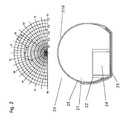
- Figure 2 shows a schematic section through a linear light source with asymmetric light emission for the external illumination of flat objects such as tables, and the example of an asymmetric spatial light distribution in the transverse direction to the linear light source.
- the linear light source consists of a long transparent base body 21 with a circular cross-section and with a light exit surface 21d and a, with respect to the vertical center plane of the long transparent base body 21 asymmetrically introduced groove-like recess 22 on the opposite side of the light exit surface 21d.
- the groove-like depression 22 may be so strongly asymmetrical that the outside wall is omitted, or in other words that the recess 22 has become an open cut in the circular cross-section.
- the transparent material constituting the main body 21 may be glass or a suitable plastic such as acrylic glass (PMMA) or polycarbonate.
- a plurality of LED 24 is mounted at defined intervals on a suitable carrier 23 with electrical contact surfaces 23a and electrically contacted by means of this carrier 23 and electrically connected to each other (parallel and / or series connection). Instead of one LED 24 each, groups of several, i. For example, 2 to 9, LED be arranged at defined intervals on the carrier 23.
- the width of the carrier 23 is for example about 7 mm, its thickness, for example, 0.1 mm.
- the LED 24 may be on the support 23 before the union with the transparent base body 21 with a - to be surrounded - transparent protective material - not shown.
- a suitable transparent protective material may be, for example, a permanently elastic silicone.
- the long transparent base body 21, together with the LED 24 fixing and electrically contacting carrier 23 is inserted into an optically transparent thin-walled shrink tubing that this the side ends of the carrier 23 conforms to the base body 21 and shields the entire structure against environmental influences.
- the groove-like recess 22 may be filled with a first relatively thin liquid transparent material which hardens after the union of the main body 21 and the carrier 23 with the LED 24 at least partially. It is preferable to use a transparent filling material which remains permanently elastic after curing.
- a suitable transparent filling material may be, for example, a permanently elastic silicone.
- the position of the groove 22, and thus the position of the LED 24, is chosen in relation to the diameter of the transparent base body 21 so that the light exit surface 21d of the transparent base body 21 as asymmetric circular cylindrical lens for the light emitted by the LED 24 in a defined spatial angle range acts.
- a depth resp. Width of the groove 22 of about 3 mm resp. 3 to 4.5 mm, a lateral offset of the groove 22 with respect to the vertical center plane of the transparent base body 21 by about 1 mm and the use of corresponding SMD LED 24 with a rotationally symmetrical beam angle of about ⁇ 60 ° can be with such a structure a Light distribution in the common center plane of all LED 24 of, for example ⁇ 60 ° and in the plane perpendicular to this center life reach a striking asymmetric light distribution of, for example, -20 ° + 35 ° or even 0 °, + 45 ° reach, with the large-scale panel-like structure strongly oblique angle can be illuminated homogeneously.
- FIG. 3 shows a schematic oblique view of a linear light source with optical elements for influencing the light distribution in the plane running along the linear light source.
- the linear light source 30 is identical except for one in all points to the light source of Figure 1.
- roof-like recesses 31b are in the direction of the beam path above the LED 34 and influence the beam path in the longitudinal direction of the linear light source 30 so that, for example, instead of a light distribution of ⁇ 60 ° such a ⁇ 75 °.
- the shape of the transversely formed recesses 31b is not limited to roof-like shapes, but may also have circular section-like, parabolic or other suitable cross-sections.
- Figures 4a to 4c show principle sketches with different carrier shapes which are bendable in both transverse directions.
- the carriers 13, 23, 33 shown in Figures 1 to 3 are flexible in the direction perpendicular to their plane and, including the mounted LED, can easily be bent in bending radii down to 3 to 5 cm. This means that the entire light sources 10, 20, 30 can be curved in this direction, for example to circular structures with a minimum diameter of the order of 10 to 20 cm.
- a curvature in the transverse direction, ie in the plane of the carrier, is allowed to be limited to the carriers 13, 23, 33 shown in FIGS. 1 to 3 when they are installed in the transparent base bodies 11, 21, 31.
- radii of curvature in the transverse direction of the order of at least 2 m are possible, which is sufficient in many cases.
- FIG. 4a shows a carrier 43, for example, approximately 0.2 mm thick, with copper on both sides.
- the upper copper layer is structured so that a continuous, meandering conductor and two pads 44 are provided for the LED.
- One of the pads 44 is connected directly to the conductor on the top.
- the other pad 44 is formed on the upper side as an island and plated through to the copper on the bottom.
- the copper is structured so that there is a continuous meandering conductor which is mirrored with respect to the longitudinal axis of the entire carrier to the conductor on the top.
- the entire carrier 43 is structured such that there is a taper 45 between the pads 44, in which all the material is concentrated near the neutral bending line, so that the carrier 43 in the desired transverse direction with bending radii of the order of a few tens cm can be curved.
- FIG. 4b shows another possibility in which the carrier is dissolved into short sections 43 with connecting surfaces 44.
- the individual sections are interconnected by flexible, not necessarily insulated strands 45, so that the sections 43 can be turned off each other approximately at right angles in the non-installed state.
- FIG. 4 c shows yet another possibility in which a stamped metal carrier is present in the sense of a so-called leadframe.
- the carrier is split in two electrically independent long sections 43a and 43b, each having a connection surface 44 and a curved conductor 45 with at least approximately square cross section at a defined repetition distance. It is not shown that the two end electrically independent long sections 43a and 43b are first connected to each other in the zone of the curved conductors 45. This connection is punched away after mounting the LED.
- Figure 5 shows the schematic oblique view of a linear light source in which the LED support is replaced by two long conductors, between which the LED are clamped.
- the long transparent main body 51 has a longitudinal groove 52 on both sides, each with an additional guide groove 52a.
- mirror-symmetrically long spring elements 56 are clamped on both sides.
- the spring elements 56 consist for example of good electrically conductive spring bronze and have, for example, a circular diameter of 0.2 mm.
- the spring members 56 are configured to include zones 56a in which the LEDs 54 may be snapped so as to be electrically contacted and mechanically held.
- the spring elements 56 have curved zones 56b, which allow a curvature in any spatial directions.
- the groove with an optically transparent, permanently elastic material such as silicone potted and / or wrapped the entire structure with an optically transparent, thin-walled shrink tubing.
- Figure 6 shows the schematic cross section through a linear light source with additional cooling and support body.
- a linear light source 60 which corresponds to one of those of Figures 1, 2, 3, 5, is installed in an elongated, preferably metallic body 61 so that it acts as a cooling and supporting body.
- the carrier and / or the LED of the light source 60 is connected to the heat sink 61 by means of a good heat-conducting medium, such as a conductive paste or a conductive adhesive.
- the illustrated body 61 is equipped with cooling fins. Of course, this does not have to be the case.
- the body 61 may be, for example, a flat plate or a corresponding U-profile or a half-circle tube.
- FIGS. 7a and 7b show schematic cross sections through linear light sources with a non-circular cross-section.
- the rod-shaped optically transparent body 71 has a groove-like recess in which a carrier 73 with a linear arrangement of packaged LED 74 is introduced.
- the light source according to FIG. 7a is convex as a whole, so that the outer shell 75 can be formed by a heat-shrinkable tube.
- it is not circular as a whole in cross-section, but it has only a circular cross-section in section, which acts as a light exit surface 71d and acts as a cylindrical lens.
- the light exit surface 71d of the light source according to FIG. 7b is also circular cylindrical, i. in cross-section circular arc.
- the light source according to FIG. 7b or its rod-shaped optically transparent body, on the other hand, is not convex as a whole.
- Such a shape is also possible, wherein the outer shell 85 can not then be formed by a shrink tube; Rather, the outer shell is then preferably present as a coating, alternatively as a glued foil. Countless other forms are possible.
Landscapes
- Engineering & Computer Science (AREA)
- Physics & Mathematics (AREA)
- Microelectronics & Electronic Packaging (AREA)
- Optics & Photonics (AREA)
- General Engineering & Computer Science (AREA)
- Illuminated Signs And Luminous Advertising (AREA)
Priority Applications (1)
| Application Number | Priority Date | Filing Date | Title |
|---|---|---|---|
| EP06405039A EP1813857A1 (fr) | 2006-01-27 | 2006-01-27 | Source de lumière |
Applications Claiming Priority (1)
| Application Number | Priority Date | Filing Date | Title |
|---|---|---|---|
| EP06405039A EP1813857A1 (fr) | 2006-01-27 | 2006-01-27 | Source de lumière |
Publications (1)
| Publication Number | Publication Date |
|---|---|
| EP1813857A1 true EP1813857A1 (fr) | 2007-08-01 |
Family
ID=36010993
Family Applications (1)
| Application Number | Title | Priority Date | Filing Date |
|---|---|---|---|
| EP06405039A Withdrawn EP1813857A1 (fr) | 2006-01-27 | 2006-01-27 | Source de lumière |
Country Status (1)
| Country | Link |
|---|---|
| EP (1) | EP1813857A1 (fr) |
Cited By (12)
| Publication number | Priority date | Publication date | Assignee | Title |
|---|---|---|---|---|
| WO2010136333A1 (fr) * | 2009-05-28 | 2010-12-02 | Osram Gesellschaft mit beschränkter Haftung | Module lumineux et dispositif lumineux |
| EP2354634A1 (fr) * | 2010-01-29 | 2011-08-10 | Chia-Hao Chang | Structure de couverture de bande de lumière |
| DE102010003073A1 (de) * | 2010-03-19 | 2011-09-22 | Osram Gesellschaft mit beschränkter Haftung | Led-Beleuchtungsvorrichtung |
| DE102014100582A1 (de) * | 2014-01-20 | 2015-07-23 | Osram Opto Semiconductors Gmbh | Leuchtmittel mit vorgebbarer Abstrahlcharakteristik und Herstellungsverfahren für einen Optikkörper |
| DE102014202759A1 (de) * | 2014-02-14 | 2015-08-20 | Osram Gmbh | Halbleiter-Röhrenlampe |
| EP2957815A1 (fr) * | 2014-06-17 | 2015-12-23 | Petrus Pfundt | Lampe ayant au moins une bande del |
| WO2016012271A1 (fr) * | 2014-07-23 | 2016-01-28 | Koninklijke Philips N.V. | Dispositif d'éclairage, luminaire et procédé de montage |
| DE202016104177U1 (de) * | 2016-07-29 | 2017-11-02 | Rehau Ag + Co | Leuchtvorrichtung |
| US10584835B2 (en) | 2016-11-23 | 2020-03-10 | Signify Holding B.V. | Lighting strip and kit |
| AT16994U1 (fr) * | 2014-11-11 | 2021-02-15 | Zumtobel Lighting Gmbh | |
| DE102019122714B4 (de) | 2019-08-23 | 2024-11-14 | Lufthansa Technik Aktiengesellschaft | Flexibler LED-Lichtschlauch |
| FI20236085A1 (en) * | 2023-09-28 | 2025-03-29 | Greenlux Lighting Solutions Oy | LED-based light fixture |
Citations (9)
| Publication number | Priority date | Publication date | Assignee | Title |
|---|---|---|---|---|
| EP1213773A1 (fr) * | 1999-07-26 | 2002-06-12 | Labosphere Institute | Lentille en masse, corps luminescent, dispositif d'eclairage et systeme d'information optique |
| US20030214809A1 (en) | 2001-08-20 | 2003-11-20 | Tsui-Tuan Wong | Colorful rope light |
| US20030224687A1 (en) * | 2002-06-03 | 2003-12-04 | Ta-Hao Fu | Method of producing an led hose light |
| US20040007980A1 (en) * | 2002-07-09 | 2004-01-15 | Hakuyo Denkyuu Kabushiki Kaisha | Tubular LED lamp |
| US20040168359A1 (en) | 2003-02-04 | 2004-09-02 | Cleaver Mark J. | Flexible illumination device for simulating neon lighting |
| US20050036310A1 (en) * | 2003-08-14 | 2005-02-17 | Ben Fan | Light string using a cladding to scatter light from light emitting diodes to present a neon light effect |
| US20050093014A1 (en) | 2003-09-25 | 2005-05-05 | Seiko Epson Corporation | Solid state light-emitting element, method for producing the element, and projector |
| DE10349788A1 (de) | 2003-10-24 | 2005-05-25 | LiSol Gesellschaft für Licht- und Solartechnik mbH | Leuchte mit einem Grundkörper aus lichtdurchlässigem Kunststoffmaterial |
| DE202005006643U1 (de) | 2005-04-26 | 2005-09-08 | Fan, Ben, Hsitzu | Flexible LED-Kabel-Beleuchtung |
-
2006
- 2006-01-27 EP EP06405039A patent/EP1813857A1/fr not_active Withdrawn
Patent Citations (9)
| Publication number | Priority date | Publication date | Assignee | Title |
|---|---|---|---|---|
| EP1213773A1 (fr) * | 1999-07-26 | 2002-06-12 | Labosphere Institute | Lentille en masse, corps luminescent, dispositif d'eclairage et systeme d'information optique |
| US20030214809A1 (en) | 2001-08-20 | 2003-11-20 | Tsui-Tuan Wong | Colorful rope light |
| US20030224687A1 (en) * | 2002-06-03 | 2003-12-04 | Ta-Hao Fu | Method of producing an led hose light |
| US20040007980A1 (en) * | 2002-07-09 | 2004-01-15 | Hakuyo Denkyuu Kabushiki Kaisha | Tubular LED lamp |
| US20040168359A1 (en) | 2003-02-04 | 2004-09-02 | Cleaver Mark J. | Flexible illumination device for simulating neon lighting |
| US20050036310A1 (en) * | 2003-08-14 | 2005-02-17 | Ben Fan | Light string using a cladding to scatter light from light emitting diodes to present a neon light effect |
| US20050093014A1 (en) | 2003-09-25 | 2005-05-05 | Seiko Epson Corporation | Solid state light-emitting element, method for producing the element, and projector |
| DE10349788A1 (de) | 2003-10-24 | 2005-05-25 | LiSol Gesellschaft für Licht- und Solartechnik mbH | Leuchte mit einem Grundkörper aus lichtdurchlässigem Kunststoffmaterial |
| DE202005006643U1 (de) | 2005-04-26 | 2005-09-08 | Fan, Ben, Hsitzu | Flexible LED-Kabel-Beleuchtung |
Cited By (27)
| Publication number | Priority date | Publication date | Assignee | Title |
|---|---|---|---|---|
| US9541274B2 (en) | 2009-05-28 | 2017-01-10 | Osram Gmbh | Illumination module and illumination device comprising a flexible carrier |
| CN102449384A (zh) * | 2009-05-28 | 2012-05-09 | 欧司朗股份有限公司 | 发光模块和发光装置 |
| CN102449384B (zh) * | 2009-05-28 | 2014-03-12 | 欧司朗股份有限公司 | 发光模块和发光装置 |
| DE102009023052B4 (de) * | 2009-05-28 | 2019-06-27 | Osram Gmbh | Leuchtmodul und Leuchtvorrichtung |
| WO2010136333A1 (fr) * | 2009-05-28 | 2010-12-02 | Osram Gesellschaft mit beschränkter Haftung | Module lumineux et dispositif lumineux |
| EP2354634A1 (fr) * | 2010-01-29 | 2011-08-10 | Chia-Hao Chang | Structure de couverture de bande de lumière |
| US8388182B2 (en) | 2010-01-29 | 2013-03-05 | Chia-Hao Chang | Lamp strip covering structure |
| DE102010003073A1 (de) * | 2010-03-19 | 2011-09-22 | Osram Gesellschaft mit beschränkter Haftung | Led-Beleuchtungsvorrichtung |
| DE102010003073B4 (de) * | 2010-03-19 | 2013-12-19 | Osram Gmbh | LED-Beleuchtungsvorrichtung |
| US8998480B2 (en) | 2010-03-19 | 2015-04-07 | Osram Gmbh | LED lighting device |
| EP3097346B1 (fr) * | 2014-01-20 | 2018-09-19 | OSRAM Opto Semiconductors GmbH | Moyen d'éclairage avec caractéristiques de radiation prédéterminée et procédé de fabrication d'un élément optique |
| US9976708B2 (en) | 2014-01-20 | 2018-05-22 | Osram Opto Semiconductors Gmbh | Lighting means having a specifiable emission characteristic and production method for an optical element |
| DE102014100582A1 (de) * | 2014-01-20 | 2015-07-23 | Osram Opto Semiconductors Gmbh | Leuchtmittel mit vorgebbarer Abstrahlcharakteristik und Herstellungsverfahren für einen Optikkörper |
| DE102014202759B4 (de) * | 2014-02-14 | 2025-06-26 | Ledvance Gmbh | Rohr für eine Halbleiter-Röhrenlampe und das Rohr aufweisende Halbleiter-Röhrenlampe |
| US9958117B2 (en) | 2014-02-14 | 2018-05-01 | Ledvance Gmbh | Semiconductor-tubular lamp, tube therefor, and production method |
| DE102014202759A1 (de) * | 2014-02-14 | 2015-08-20 | Osram Gmbh | Halbleiter-Röhrenlampe |
| US10323801B2 (en) | 2014-02-14 | 2019-06-18 | Ledvance Gmbh | Semiconductor tubular lamp, tube therefor, and production method |
| EP2957815A1 (fr) * | 2014-06-17 | 2015-12-23 | Petrus Pfundt | Lampe ayant au moins une bande del |
| WO2016012271A1 (fr) * | 2014-07-23 | 2016-01-28 | Koninklijke Philips N.V. | Dispositif d'éclairage, luminaire et procédé de montage |
| EP2990717A1 (fr) * | 2014-07-23 | 2016-03-02 | Koninklijke Philips N.V. | Dispositif d'éclairage, luminaire et procédé d'assemblage |
| JP2017520898A (ja) * | 2014-07-23 | 2017-07-27 | フィリップス ライティング ホールディング ビー ヴィ | 照明装置、照明器具及び組み立て方法 |
| RU2685691C2 (ru) * | 2014-07-23 | 2019-04-23 | Филипс Лайтинг Холдинг Б.В. | Осветительное устройство, светильник и способ сборки |
| AT16994U1 (fr) * | 2014-11-11 | 2021-02-15 | Zumtobel Lighting Gmbh | |
| DE202016104177U1 (de) * | 2016-07-29 | 2017-11-02 | Rehau Ag + Co | Leuchtvorrichtung |
| US10584835B2 (en) | 2016-11-23 | 2020-03-10 | Signify Holding B.V. | Lighting strip and kit |
| DE102019122714B4 (de) | 2019-08-23 | 2024-11-14 | Lufthansa Technik Aktiengesellschaft | Flexibler LED-Lichtschlauch |
| FI20236085A1 (en) * | 2023-09-28 | 2025-03-29 | Greenlux Lighting Solutions Oy | LED-based light fixture |
Similar Documents
| Publication | Publication Date | Title |
|---|---|---|
| DE102007030186B4 (de) | Lineare LED-Lampe und Leuchtensystem mit derselben | |
| EP1859196B1 (fr) | Module emetteur de lumiere equipe de diodes electroluminescentes et de goujons d'assemblage permettant de monter un element optique | |
| DE102008025398B4 (de) | Schutzumhüllung für ein LED-Band | |
| DE102011076613B4 (de) | LED-Leuchte und Verfahren zur Herstellung der LED-Leuchte | |
| EP2976570B1 (fr) | Module à led et la luminaire avec au moins un module led. | |
| DE102010030863A1 (de) | LED-Leuchtvorrichtung und Verfahren zum Herstellen einer LED-Leuchtvorrichtung | |
| EP1854152A2 (fr) | Source lumineuse | |
| EP1813857A1 (fr) | Source de lumière | |
| EP3015761B1 (fr) | Dispositif d'éclairage avec élément optique | |
| DE102009023052A1 (de) | Leuchtmodul und Leuchtvorrichtung | |
| EP2805106B1 (fr) | Luminaire pour locaux humides pourvu de del | |
| DE102011086628A1 (de) | Rohrförmige LED-Lampe | |
| DE102018123968B4 (de) | Beleuchtungsvorrichtung mit einer Light-Engine aus einem Streifen | |
| EP3056805B2 (fr) | Optique allongée pour module à del | |
| DE102017116932B4 (de) | Leuchtvorrichtung mit Linse und Verfahren zu dessen Herstellung | |
| EP3537039A1 (fr) | Tuyau d'encapsulation pour un module linéaire de diode électroluminescente et un module linéaire de diode électroluminescente le comprenant | |
| DE102016002910B4 (de) | Vollvergossenes,flexibles Leuchtdiodenband mit homogenem Lichtaustritt und 360° -Abstrahlung und Verfahren zu dessen Herstellung | |
| DE102013225982B4 (de) | Beleuchtungseinrichtung mit einem Spannelement | |
| DE102012201788A1 (de) | Rohrförmige LED-Lampe | |
| DE102017109836B4 (de) | Leuchtmittel mit Kühlkörper | |
| EP3218648B1 (fr) | Lampe à led pourvue d'un guide de lumière coudé | |
| WO2010142281A1 (fr) | Système d'éclairage étanche à l'humidité et procédé de fabrication associé | |
| AT15839U1 (de) | LED-Lichtquelle | |
| DE102012204510A1 (de) | Rohrförmige LED-Lampe | |
| DE102012103198B4 (de) | Trägereinrichtung für ein Leuchtmodul und Verfahren zu deren Herstellung |
Legal Events
| Date | Code | Title | Description |
|---|---|---|---|
| PUAI | Public reference made under article 153(3) epc to a published international application that has entered the european phase |
Free format text: ORIGINAL CODE: 0009012 |
|
| AK | Designated contracting states |
Kind code of ref document: A1 Designated state(s): AT BE BG CH CY CZ DE DK EE ES FI FR GB GR HU IE IS IT LI LT LU LV MC NL PL PT RO SE SI SK TR |
|
| AX | Request for extension of the european patent |
Extension state: AL BA HR MK YU |
|
| RAP1 | Party data changed (applicant data changed or rights of an application transferred) |
Owner name: LUCEA AG |
|
| 17P | Request for examination filed |
Effective date: 20080129 |
|
| 17Q | First examination report despatched |
Effective date: 20080310 |
|
| AKX | Designation fees paid |
Designated state(s): AT BE BG CH CY CZ DE DK EE ES FI FR GB GR HU IE IS IT LI LT LU LV MC NL PL PT RO SE SI SK TR |
|
| STAA | Information on the status of an ep patent application or granted ep patent |
Free format text: STATUS: THE APPLICATION IS DEEMED TO BE WITHDRAWN |
|
| 18D | Application deemed to be withdrawn |
Effective date: 20110802 |