EP1813869A2 - Éléments de paroi de chambre de combustion de turbine à gaz - Google Patents
Éléments de paroi de chambre de combustion de turbine à gaz Download PDFInfo
- Publication number
- EP1813869A2 EP1813869A2 EP06256491A EP06256491A EP1813869A2 EP 1813869 A2 EP1813869 A2 EP 1813869A2 EP 06256491 A EP06256491 A EP 06256491A EP 06256491 A EP06256491 A EP 06256491A EP 1813869 A2 EP1813869 A2 EP 1813869A2
- Authority
- EP
- European Patent Office
- Prior art keywords
- wall element
- pedestals
- outlet
- pattern
- downstream
- Prior art date
- Legal status (The legal status is an assumption and is not a legal conclusion. Google has not performed a legal analysis and makes no representation as to the accuracy of the status listed.)
- Withdrawn
Links
- 239000002826 coolant Substances 0.000 claims abstract description 32
- 238000011144 upstream manufacturing Methods 0.000 claims abstract description 20
- 238000012546 transfer Methods 0.000 claims description 9
- 238000001816 cooling Methods 0.000 description 33
- 238000002485 combustion reaction Methods 0.000 description 8
- 239000007789 gas Substances 0.000 description 7
- 239000000446 fuel Substances 0.000 description 6
- 230000001141 propulsive effect Effects 0.000 description 5
- NJPPVKZQTLUDBO-UHFFFAOYSA-N novaluron Chemical compound C1=C(Cl)C(OC(F)(F)C(OC(F)(F)F)F)=CC=C1NC(=O)NC(=O)C1=C(F)C=CC=C1F NJPPVKZQTLUDBO-UHFFFAOYSA-N 0.000 description 4
- 239000000203 mixture Substances 0.000 description 2
- 230000009467 reduction Effects 0.000 description 2
- 230000003466 anti-cipated effect Effects 0.000 description 1
- 238000013459 approach Methods 0.000 description 1
- 230000008901 benefit Effects 0.000 description 1
- 238000005266 casting Methods 0.000 description 1
- 239000000567 combustion gas Substances 0.000 description 1
- 230000006835 compression Effects 0.000 description 1
- 238000007906 compression Methods 0.000 description 1
- 238000010276 construction Methods 0.000 description 1
- 238000007796 conventional method Methods 0.000 description 1
- 239000012809 cooling fluid Substances 0.000 description 1
- 230000001419 dependent effect Effects 0.000 description 1
- 238000013461 design Methods 0.000 description 1
- 238000009792 diffusion process Methods 0.000 description 1
- 230000000694 effects Effects 0.000 description 1
- 230000006872 improvement Effects 0.000 description 1
- 238000012986 modification Methods 0.000 description 1
- 230000004048 modification Effects 0.000 description 1
- 230000037361 pathway Effects 0.000 description 1
- 239000007921 spray Substances 0.000 description 1
Images


Classifications
-
- F—MECHANICAL ENGINEERING; LIGHTING; HEATING; WEAPONS; BLASTING
- F23—COMBUSTION APPARATUS; COMBUSTION PROCESSES
- F23R—GENERATING COMBUSTION PRODUCTS OF HIGH PRESSURE OR HIGH VELOCITY, e.g. GAS-TURBINE COMBUSTION CHAMBERS
- F23R3/00—Continuous combustion chambers using liquid or gaseous fuel
- F23R3/002—Wall structures
-
- F—MECHANICAL ENGINEERING; LIGHTING; HEATING; WEAPONS; BLASTING
- F23—COMBUSTION APPARATUS; COMBUSTION PROCESSES
- F23R—GENERATING COMBUSTION PRODUCTS OF HIGH PRESSURE OR HIGH VELOCITY, e.g. GAS-TURBINE COMBUSTION CHAMBERS
- F23R3/00—Continuous combustion chambers using liquid or gaseous fuel
- F23R3/02—Continuous combustion chambers using liquid or gaseous fuel characterised by the air-flow or gas-flow configuration
- F23R3/04—Air inlet arrangements
- F23R3/06—Arrangement of apertures along the flame tube
-
- F—MECHANICAL ENGINEERING; LIGHTING; HEATING; WEAPONS; BLASTING
- F23—COMBUSTION APPARATUS; COMBUSTION PROCESSES
- F23R—GENERATING COMBUSTION PRODUCTS OF HIGH PRESSURE OR HIGH VELOCITY, e.g. GAS-TURBINE COMBUSTION CHAMBERS
- F23R2900/00—Special features of, or arrangements for continuous combustion chambers; Combustion processes therefor
- F23R2900/03042—Film cooled combustion chamber walls or domes
-
- Y—GENERAL TAGGING OF NEW TECHNOLOGICAL DEVELOPMENTS; GENERAL TAGGING OF CROSS-SECTIONAL TECHNOLOGIES SPANNING OVER SEVERAL SECTIONS OF THE IPC; TECHNICAL SUBJECTS COVERED BY FORMER USPC CROSS-REFERENCE ART COLLECTIONS [XRACs] AND DIGESTS
- Y02—TECHNOLOGIES OR APPLICATIONS FOR MITIGATION OR ADAPTATION AGAINST CLIMATE CHANGE
- Y02T—CLIMATE CHANGE MITIGATION TECHNOLOGIES RELATED TO TRANSPORTATION
- Y02T50/00—Aeronautics or air transport
- Y02T50/60—Efficient propulsion technologies, e.g. for aircraft
Definitions
- This invention relates to combustors for gas turbine engines, and in particular to wall elements for use in wall structures of combustors of gas turbine engines.
- the tiles typically overlap, often with a relatively cooler side of an upstream tile overlapping a hotter side of a downstream tile. This means that cooling air from the cooler side of the upstream tile can pass onto the hotter side of the downstream tile also to provide a cooling film.
- Projections such as pedestals are generally provided on the rear of the tiles, extending toward the outer wall, to provide heat transfer.
- the pedestals are typically arranged in staggered rows to maximise heat transfer. Cooling of the tiles therefore takes place on the cooler side by convection from the projections and on the hotter side by film cooling.
- these known tile configurations are sufficient to cool the tile, they use a significant amount of cooling airflow that could otherwise be used to improve propulsive efficiency of the engine.
- the pedestals cause turbulence in the cooling airflow exiting an upstream tile. This turbulence increases the amount of mixing of the film cooling air and the combustion products.
- the object of the present invention is therefore to provide an improved cooling film across the surface of the downstream tile and thereby increasing the life of the tile.
- a wall element arrangement for a gas turbine engine combustor comprising an upstream wall element overlapping a downstream wall element and defining a gap and an outlet therebetween; in use, a coolant exits the outlet to provide a coolant film across at least a part of the downstream wall element, characterized in that the outlet has a smaller dimension normal to the downstream wall element than the gap thereby increasing the velocity of the coolant flow across the downstream wall element.
- a plurality of projections is provided on an outer surface of the wall element to facilitate heat transfer to the coolant flow.
- the plurality of projections comprises a first pattern and a second pattern, the first pattern spaced from the outlet.
- the outlet has a smaller cross-sectional area than the gap.
- the upstream and downstream wall elements define a convergent portion leading to the outlet.
- the upstream and downstream wall elements define a constant cross-section portion of the outlet, the constant cross-section portion positioned downstream of the convergent portion.
- the projections in the second pattern are adjacent the convergent portion and/or the constant cross-section portion.
- a trailing edge of the projections of the second pattern is aligned with the exit plane of the outlet, but the trailing edge may be within the region of the convergent portion and/or the constant cross-section portion.
- the first pattern comprises a staggered array of pedestals.
- the second pattern comprises elongate pedestals.
- the elongate pedestals define coolant flow passages therebetween, the elongate pedestals are tapered in the downstream direction such that the coolant flow is diffused across the outlet.
- the elongate pedestals are tapered in the upstream direction such that the passages are convergent laterally and towards the outlet to further increase the velocity of the coolant flow across the downstream wall element.
- the second pattern comprises pedestals arranged substantially in-line. Adjacent pedestals consecutively increase or decrease in cross-sectional area.
- a gas turbine engine is generally indicated at 10 and comprises, in axial flow (arrow A) series, an air intake 11, a propulsive fan 12, an intermediate pressure compressor 13, a high pressure compressor 14, combustion equipment 15, a high pressure turbine 16, an intermediate pressure turbine 17, a low pressure turbine 18 and an exhaust nozzle 19.
- the engine has a rotational axis X-X.
- the gas turbine engine 10 works in the conventional manner so that air entering the intake 11 is accelerated by the fan to produce two air flows: a first air flow A into the intermediate pressure compressor 13 and a second air flow B which provides propulsive thrust.
- the intermediate pressure compressor 13 compresses the airflow A directed into it before delivering that air to the high pressure compressor 14 where further compression takes place.
- the compressed air exhausted from the high-pressure compressor 14 is directed into the combustion equipment 15 where it is mixed with fuel and the mixture combusted.
- the resultant hot combustion products then expand through, and thereby drive, the high, intermediate and low-pressure turbines 16, 17 and 18 before being exhausted through the nozzle 19 to provide additional propulsive thrust.
- the high, intermediate and low-pressure turbines 16, 17 and 18 respectively drive the high and intermediate pressure compressors 14 and 13 and the fan 12 by suitable interconnecting shafts.
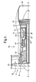
- the combustor 15 is constituted by an annular combustion chamber 20 having radially inner and outer double-wall structures 21 and 22 respectively.
- the combustor 15 is secured to a wall 23 by a plurality of pins 24 (only one of which is shown).
- Fuel is directed into the chamber 20 through a number of fuel nozzles 25 located at the upstream end 26 of the chamber 20.
- the fuel nozzles are circumferentially spaced around the engine 10 and serve to spray fuel into air (flow A) derived from the high-pressure compressor 14. The resultant fuel/air mixture is then combusted within the chamber 20.
- the combustion process which takes place within the chamber 20, naturally generates a large amount of heat. It is necessary therefore to arrange the inner and outer wall structures 21 and 22 such that they are capable of withstanding the heat.
- the radially inner and outer double-wall structures 21 and 22 each comprise an external wall in the form of a liner 27 and an internal wall 28.
- the terms 'internal' and 'external' are with respect to the combustion chamber 20.
- the internal wall 28 is made up of a plurality of discrete wall elements in the form of tiles 29A and 29B.
- Each of the tiles 29A, 29B has circumferentially extending edges 30 and 31, and the tiles are positioned adjacent each other, such that the edges 30 and 31 of adjacent tiles 29A, 29B overlap each other. Alternatively, the edges 30, 31 of adjacent tiles can abut each other.
- Each tile 29A, 29B comprises a base portion 32 which is spaced from the liner 27 to define therebetween a space 38 for the flow of cooling fluid in the form of cooling air as will be explained below.
- Heat removal features in the form of projections or pedestals 40, are provided on the base portion 32 and extend from the tile's cooler side into the space 38 towards the liner 27.
- Conventional securing means in the form of a plurality of threaded plugs extend from the base portions 32 of the tiles 29A, 29B through apertures in the outer wall 27. Nuts are screwed onto the plugs to secure the tiles 29A, 29B to the external wall 27.
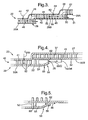
- Feed holes 42 are provided in the liner 27 to permit air from the high pressure compressor 14 to pass into the space 38 as illustrated by the arrows 44. Air entering the space will pass forwards and backwards (with respect to the main airflow A through the engine) as illustrated by the arrows 46. At the edges 30, 31 of the tiles 29A, 29B the air will pass over the inner surface 41 of an adjacent tile 29B. For forward flowing air 46, the path is simply over the inner hot surface 41 of an adjacent downstream tile 29B which will be offset outwardly as illustrated in the figure. For backwards flowing cooling air, as illustrated by the arrows 48, the air will turn 180° to pass in a downstream direction with the air from the adjacent upstream tile 29A, 29B.
- this prior art tile configuration is sufficient to cool the tiles 29A and 29B, it uses a significant amount of cooling airflow that could otherwise be used to improve propulsive efficiency of the engine. Furthermore, the pedestals cause turbulence in the cooling airflow exiting an upstream tile 29A. This turbulence increases the amount of mixing of the film cooling air and the hot combustion products and reduces the axial distance over which the cooling film is effective.
- the object of the present invention is therefore to provide an improved cooling film across the surface of the downstream tile and thereby increasing the life of the tile.
- it is an objective to reduce the amount of turbulence in the airflow and increase the velocity of the cooling film.
- a wall element arrangement 50A, 50B in accordance with the present invention is generally similar to and operates as the arrangement described with reference to Figure 3 and therefore some of the same reference numerals are used.
- the wall element arrangement 50A, 50B comprises an upstream wall element 50A overlapping a downstream wall element 50B.
- the wall elements define a gap 37 (38 in Fig 3) between them and also between walls and the liner 27. Cooling air C enters the gap 37 (through feed holes not shown) before passing through an outlet 35, between wall elements 50A and 50B, to provide a coolant film D across at least a part of the downstream wall element 50B.
- the outlet dimensions are generally the same as the flow area for the remainder of the wall element, however, the present invention is concerned with the outlet 35 having a smaller dimension normal to the downstream wall element 50B than the gap 37, viz T outlet ⁇ T gap in Figure 4. This reduces the thickness of the coolant film and increases the velocity of the coolant flow across at the downstream wall element 50B. Thus the coolant flow is effective further across the downstream wall element 50B.
- the outlet 35 has a smaller cross-sectional area than the gap 37.
- the downstream edge 31 of the tile 50A is curved towards the outer surface 39 of the tile 50B to define a convergent portion 56 of the outlet 35.
- the outlet 35 further comprises constant a cross-section portion 56, defined between the wall elements 50A, 50B.
- the constant cross-section portion 58 is positioned downstream of the convergent portion 58 and allows the coolant air increased distance to form a reduced thickness film before exiting across the downstream tile 50B.
- the wall elements 50A, 50B each comprise a plurality of projections 40, generally cylindrical in shape, and extending from an outer surface 41 of each tile's base portion 32.
- the projections or pedestals facilitate heat transfer to the coolant flow as known in the art.
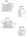
- the present invention is realized by an array of projections in a regular staggered pattern, however, in a preferred embodiment as shown in figures 4, 6, 7, 9 and 10, a first pattern 52 is spaced from the downstream edge 31 of the tile 50A by the second pattern 54, which is adjacent to the edge 31.
- the first pattern 62 is a conventional staggered array of projections comprising rows of pedestals that are regularly spaced and pitched, each row evenly offset from the adjacent. This offset allows the coolant flow, passing around one row of projections, to impinge on the downstream and offset row of projections, maximizing heat transfer from the base portion 32 of the tile 50A (and 50B).
- the second pattern 54 comprises elongate pedestals 54.
- the elongate pedestals 54 define coolant flow passages 53 and at least some of the elongate pedestals 54' are tapered in the downstream direction such that the coolant flow is diffused across the outlet 35.
- providing additional and lateral diffusion of the coolant flow additionally smooth the flow to reduce turbulence in the flow.
- This embodiment is also useful where the upstream part of the downstream tile 50B is known to get particularly hot.
- the stepped tile arrangement can cause combustion gases to be drawn around the downstream edge 31 and onto the downstream tile 50B.
- Figure 7 shows an alternative embodiment to Figure 6, where the elongate pedestals 54" are tapered in the upstream direction and define passages 55 which are laterally convergent towards the outlet 35 to further increase the velocity of the coolant flow across the downstream wall element 50B.
- Figures 6 and 7 show preferred embodiments having diverging or converging passages (53, 55) defined by tapering pedestals (54', 54")
- the elongate pedestals 54 may be of a constant width as show in Figures 10 and 10A.
- these pedestals preferably comprise aerodynamic leading and trailing tips 80, 82 ( Figure 5 and 10A) so that the cooling air is less disturbed on entry to and exit from the array of elongate pedestals 54.
- the leading and trailing tips 80, 82 are preferably circular in section, although other shapes are possible such as elliptical and pointed.
- the pedestals 54 are preferably a single elongate shape, it is possible for these pedestals to be substituted by a plurality of discrete projections 60 as shown in figure 8.
- the plurality of pedestals 60 are aligned in close proximity to one another and preferably where a gap between pedestals is less than the corresponding width of the pedestal.
- This arrangement has the additional advantage of increasing the surface area for heat removal near to the edge 31 of the tile 50A.
- there may also be a slight increase in turbulence thus, it would be a matter of simple design choice and compromise between the less turbulent of coolant flow using the elongate projections 54 and greater heat removal using a plurality of aligned projections 60 for any given situation.
- Figure 9 shows a third arrangement of pedestals extending from the base portion 32 of the tile 50A according to the invention.
- the tile 50A may be substituted in place of one or both tiles 29A, 29B in Figures 2 and 3.
- the pedestals 40 are arranged in first and second patterns 52, 54.
- the second pattern 54 comprises an array of substantially in-line pedestals 40 with respect to the cooling airflow direction arrow D.
- This second pattern 54 is adjacent, in this instance, a downstream edge 31 of the tile 50.
- air passing through the second pattern 54 of pedestals 40 moves in a generally straight line as illustrated by the arrow 56.
- the first pattern 52 is spaced from the edge 31 by the second pattern 54, and comprises an array of staggered pedestals. Accordingly, for air to pass through the first pattern 52 it must follow a tortuous route where impingement on downstream pedestals is maximised and therefore is particularly effective in removing heat from the pedestals 40 and thus tile 50A.
- the tile 50 has the second pattern 54 of pedestals 40 adjacent each edge 30, 31, with the first pattern 52 extending therebetween.
- the staggered pattern 52 will provide for increased or maximum heat transfer. As the air approaches either of the edges 30, 31 it will pass into the pattern 54 and therefore moves in a substantially straight line that will help to smooth the air flow egressing and remove the turbulence from the air that would be caused by the prior art pedestal tiles.
- a tile of the present invention therefore produces a film of cooling air to pass over an inner surface of the tile 50B that is less turbulent than the prior art tiles and which provides improved film cooling effectiveness.
- This improvement reduces the adiabitic wall temperature and reduces heat exchange between the cooling film and the tile surface, giving a reduction in tile temperature for a given cooling air flow.
- the same temperature may be maintained with reduced levels of cooling air.
- Figure 9 shows three rows of projections, aligned with one another, to direct the flow in a straight line
- the present invention is realized by having at least two (rows of) projections aligned before the tile edge 31. It is anticipated that where particularly large tiles 50A, B are used up to ten rows of projections may be aligned. The number of aligned rows will depend on their effectiveness of straightening the flow and the thermal gradient throughout the host tile 50A and the temperature regime and length of the downstream tile 50B. It should be appreciated by the skilled artisan that the projections 40 need not be circular in cross section and instead could be elliptical, square or any other convenient cross-sectional shape.
- Figure 9A shows an embodiment similar to figure 9, however, in this case the second pedestal array 54 provides enhanced cooling to the downstream edge region 31 of the tile.
- the downstream edge 31 of the tile is sensitive to a reduced amount of cooling - by virtue of aligning the pedestals 54 in figure 9 to reduce turbulence, hence less cooling air impingement on the pedestals - additional pedestals are provided.
- the array of pedestals 52' comprise in-line rows of pedestals to ensure minimal turbulence, however, there are a greater number of pedestals.
- the number of pedestals is increased at least some pedestals comprise a smaller cross-sectional area. It is intended that the total surface area available for heat transfer in region 54' is about the same as in region 52 for a given surface area of tile. Thus, an even temperature across the tile and particularly at its downstream edge 31 is maintained.
- the total number of pedestals in the array 54' may be increased by including further rows or columns or both as shown in figure 9A.
- FIG 10 shows a fourth embodiment of tile 50A according to the present invention.
- the tile 50A again has a first pattern 52 of pedestals 40 in a staggered array, arranged spaced from the edges 30, 31.
- the second pattern 54 is provided by a plurality of fins 66 which are elongate members defining straight parallel pathways 68 therebetween providing for air to flow in a straight line as illustrated by arrow D.
- the second pattern 68 is again provided adjacent each edge 30, 31.
- Figure 10A shows the elongate pedestals 66 comprising more aerodynamic leading and trailing tips 80, 82 so that the cooling air is less disturbed on entry to and exit from the array of elongate pedestals 60.
- the leading and trailing tips 80, 82 are circular in section, although other shapes are possible such as elliptical and pointed.
- the projections on the outer surface of the tiles could have a wide range of patterns providing for different flow paths to maximise heat transfer on the inner and outer surfaces of the tile.
- Figure 10 illustrates rectangular cross section fins, different shape fins could be provided to reduce the amount of turbulence in the air flow egressing the tile 50.
- the length of the fins 66 is dependent on the temperature gradients of both the host tile and the downstream tile. Generally, a longer fin 66 provides a less turbulent air flow 70, but then there is a greater area of the host tile 50 where there is a reduction in the amount of heat removal.
- the elongate pedestal 54 is shown with its trailing edge 82 aligned with the exit plane of the outlet 35. This is preferred where the pedestals 54' are tapered towards the gap 35 or edge 31 and thus causes minimal turbulence in the cooling film over the downstream tile 50B. Where the pedestals 66, 68, 54" are not tapered towards the gap 35 or edge 31 and have a bluff downstream end, it is preferable for the trailing edge 82 to be positioned upstream of the outlet 35 to enable the flow to smooth out before exiting the outlet. Whatever position the pedestals 54 are it is preferable for their trailing edges 82 to be adjacent the convergent portion 56, i.e. within the region where the gap 37 narrows to the outlet. In this way, not only do the pedestals provide heat removal from the downstream edge 31, but also reduce the cross-sectional area of the outlet so to limit the convergence of the portion 56.
Landscapes
- Engineering & Computer Science (AREA)
- Chemical & Material Sciences (AREA)
- Combustion & Propulsion (AREA)
- Mechanical Engineering (AREA)
- General Engineering & Computer Science (AREA)
- Turbine Rotor Nozzle Sealing (AREA)
Applications Claiming Priority (2)
| Application Number | Priority Date | Filing Date | Title |
|---|---|---|---|
| GB0601438A GB0601438D0 (en) | 2006-01-25 | 2006-01-25 | Wall elements for gas turbine engine combustors |
| GB0601412A GB0601412D0 (en) | 2006-01-25 | 2006-01-25 | Wall elements for gas turbine engine combustors |
Publications (2)
| Publication Number | Publication Date |
|---|---|
| EP1813869A2 true EP1813869A2 (fr) | 2007-08-01 |
| EP1813869A3 EP1813869A3 (fr) | 2013-08-14 |
Family
ID=37963483
Family Applications (1)
| Application Number | Title | Priority Date | Filing Date |
|---|---|---|---|
| EP06256491.9A Withdrawn EP1813869A3 (fr) | 2006-01-25 | 2006-12-20 | Éléments de paroi de chambre de combustion de turbine à gaz |
Country Status (3)
| Country | Link |
|---|---|
| US (1) | US7886541B2 (fr) |
| EP (1) | EP1813869A3 (fr) |
| JP (1) | JP2007198727A (fr) |
Cited By (4)
| Publication number | Priority date | Publication date | Assignee | Title |
|---|---|---|---|---|
| EP2187022A4 (fr) * | 2007-09-25 | 2015-03-11 | Mitsubishi Heavy Ind Ltd | Structure de refroidissement pour une chambre de combustion de turbine à gaz |
| EP2947296A1 (fr) * | 2014-04-04 | 2015-11-25 | United Technologies Corporation | Trous de refroidissement de rails angulaires d'une chambre de combustion d'une turbomachine |
| CN106812556A (zh) * | 2017-03-16 | 2017-06-09 | 中国科学院工程热物理研究所 | 一种燃气轮机热端冷却结构及具有其的燃气轮机 |
| US10344977B2 (en) | 2016-02-24 | 2019-07-09 | Rolls-Royce Plc | Combustion chamber having an annular outer wall with a concave bend |
Families Citing this family (30)
| Publication number | Priority date | Publication date | Assignee | Title |
|---|---|---|---|---|
| US8647053B2 (en) * | 2010-08-09 | 2014-02-11 | Siemens Energy, Inc. | Cooling arrangement for a turbine component |
| US8931280B2 (en) * | 2011-04-26 | 2015-01-13 | General Electric Company | Fully impingement cooled venturi with inbuilt resonator for reduced dynamics and better heat transfer capabilities |
| US8925326B2 (en) | 2011-05-24 | 2015-01-06 | General Electric Company | System and method for turbine combustor mounting assembly |
| US8919127B2 (en) | 2011-05-24 | 2014-12-30 | General Electric Company | System and method for flow control in gas turbine engine |
| US8826667B2 (en) * | 2011-05-24 | 2014-09-09 | General Electric Company | System and method for flow control in gas turbine engine |
| US8840371B2 (en) | 2011-10-07 | 2014-09-23 | General Electric Company | Methods and systems for use in regulating a temperature of components |
| US20130180252A1 (en) * | 2012-01-18 | 2013-07-18 | General Electric Company | Combustor assembly with impingement sleeve holes and turbulators |
| US20140033726A1 (en) * | 2012-08-06 | 2014-02-06 | Wei Chen | Liner cooling assembly for a gas turbine system |
| EP2946092B1 (fr) * | 2013-01-17 | 2019-04-17 | United Technologies Corporation | Ensemble revêtement pour chambre de combustion de turbine à gaz équipé d'un profil hyperbolique convergent |
| CA2904200A1 (fr) | 2013-03-05 | 2014-09-12 | Rolls-Royce Corporation | Tuile de chambre de combustion a effusion, convexion, impact a double paroi |
| CN105339738B (zh) * | 2013-06-27 | 2017-07-04 | 西门子股份公司 | 紧固隔热罩块至支撑结构,以及隔热罩 |
| EP2837887B1 (fr) * | 2013-08-15 | 2019-06-12 | Ansaldo Energia Switzerland AG | Chambre de combustion d'une turbine à gaz avec refroidissement de doublure optimisée de chute de pression |
| EP3071885B1 (fr) * | 2013-11-21 | 2020-03-11 | United Technologies Corporation | Structure à parois multiples pour moteur à turbine dotée d'éléments de refroidissement internes |
| WO2015117139A1 (fr) * | 2014-02-03 | 2015-08-06 | United Technologies Corporation | Chemise thermique étagée pour une chambre de combustion de moteur à turbine |
| US10533745B2 (en) * | 2014-02-03 | 2020-01-14 | United Technologies Corporation | Film cooling a combustor wall of a turbine engine |
| US9410702B2 (en) | 2014-02-10 | 2016-08-09 | Honeywell International Inc. | Gas turbine engine combustors with effusion and impingement cooling and methods for manufacturing the same using additive manufacturing techniques |
| PT3129709T (pt) * | 2014-04-09 | 2019-02-06 | Avio Spa | Câmara de combustão de um motor propulsor líquido |
| GB201412460D0 (en) | 2014-07-14 | 2014-08-27 | Rolls Royce Plc | An Annular Combustion Chamber Wall Arrangement |
| US20170167729A1 (en) * | 2014-07-30 | 2017-06-15 | Siemens Aktiengesellschaft | Multiple feed platefins within a hot gas path cooling system in a combustor basket in a combustion turbine engine |
| GB201501971D0 (en) | 2015-02-06 | 2015-03-25 | Rolls Royce Plc | A combustion chamber |
| GB2545459B (en) * | 2015-12-17 | 2020-05-06 | Rolls Royce Plc | A combustion chamber |
| US10830448B2 (en) * | 2016-10-26 | 2020-11-10 | Raytheon Technologies Corporation | Combustor liner panel with a multiple of heat transfer augmentors for a gas turbine engine combustor |
| US20180299126A1 (en) * | 2017-04-18 | 2018-10-18 | United Technologies Corporation | Combustor liner panel end rail |
| US20180306113A1 (en) * | 2017-04-19 | 2018-10-25 | United Technologies Corporation | Combustor liner panel end rail matching heat transfer features |
| US10473331B2 (en) * | 2017-05-18 | 2019-11-12 | United Technologies Corporation | Combustor panel endrail interface |
| US10830436B2 (en) | 2018-03-20 | 2020-11-10 | Pratt & Whitney Canada Corp. | Combustor heat shield edge cooling |
| US11268696B2 (en) * | 2018-10-19 | 2022-03-08 | Raytheon Technologies Corporation | Slot cooled combustor |
| US11156363B2 (en) * | 2018-12-07 | 2021-10-26 | Raytheon Technologies Corporation | Dirt tolerant pins for combustor panels |
| FR3111414B1 (fr) * | 2020-06-15 | 2022-09-02 | Safran Helicopter Engines | Production par fabrication additive de pièces complexes |
| JP7614980B2 (ja) * | 2021-08-25 | 2025-01-16 | 三菱重工航空エンジン株式会社 | 燃焼器パネル、及びガスタービン用燃焼器 |
Family Cites Families (23)
| Publication number | Priority date | Publication date | Assignee | Title |
|---|---|---|---|---|
| GB762596A (en) * | 1954-02-18 | 1956-11-28 | Armstrong Siddeley Motors Ltd | A combustion chamber, particularly for a gas turbine engine |
| DE1476727A1 (de) * | 1964-10-20 | 1969-09-25 | Bristol Siddeley Engines Ltd | Kanalanordnung zur Kuehlung von Wandungen,die ein heisses stroemendes Medium von einem kuehleren stroemenden Medium hoeheren Druckes trennen |
| GB1079186A (en) | 1965-05-06 | 1967-08-16 | Rolls Royce | Improvements in gas turbine engines |
| GB1197197A (en) | 1967-12-19 | 1970-07-01 | Inst Elektrosvarki Im Akademik | Sequence Timer for Electric Resistance Welders |
| GB1550368A (en) * | 1975-07-16 | 1979-08-15 | Rolls Royce | Laminated materials |
| US4184326A (en) * | 1975-12-05 | 1980-01-22 | United Technologies Corporation | Louver construction for liner of gas turbine engine combustor |
| US4050241A (en) * | 1975-12-22 | 1977-09-27 | General Electric Company | Stabilizing dimple for combustion liner cooling slot |
| US4259842A (en) * | 1978-12-11 | 1981-04-07 | General Electric Company | Combustor liner slot with cooled props |
| US4302941A (en) * | 1980-04-02 | 1981-12-01 | United Technologies Corporation | Combuster liner construction for gas turbine engine |
| GB2087065B (en) * | 1980-11-08 | 1984-11-07 | Rolls Royce | Wall structure for a combustion chamber |
| GB2125950B (en) | 1982-08-16 | 1986-09-24 | Gen Electric | Gas turbine combustor |
| US4642993A (en) * | 1985-04-29 | 1987-02-17 | Avco Corporation | Combustor liner wall |
| GB9803291D0 (en) * | 1998-02-18 | 1998-04-08 | Chapman H C | Combustion apparatus |
| US6402470B1 (en) * | 1999-10-05 | 2002-06-11 | United Technologies Corporation | Method and apparatus for cooling a wall within a gas turbine engine |
| US6254334B1 (en) * | 1999-10-05 | 2001-07-03 | United Technologies Corporation | Method and apparatus for cooling a wall within a gas turbine engine |
| GB9926257D0 (en) * | 1999-11-06 | 2000-01-12 | Rolls Royce Plc | Wall elements for gas turbine engine combustors |
| GB2356042A (en) | 1999-11-06 | 2001-05-09 | Rolls Royce Plc | Improvements in or relating to wall elements for gas turbine engines |
| US20020066273A1 (en) * | 2000-12-04 | 2002-06-06 | Mitsubishi Heavy Industries, Ltd. | Plate fin and combustor using the plate fin |
| JP2002242702A (ja) * | 2001-02-14 | 2002-08-28 | Mitsubishi Heavy Ind Ltd | ガスタービン燃焼器壁面冷却構造 |
| GB2373319B (en) * | 2001-03-12 | 2005-03-30 | Rolls Royce Plc | Combustion apparatus |
| US6530225B1 (en) * | 2001-09-21 | 2003-03-11 | Honeywell International, Inc. | Waffle cooling |
| JP3665007B2 (ja) | 2001-10-18 | 2005-06-29 | 三菱重工業株式会社 | ガスタービン燃焼器のプレートフィン構造及びガスタービン燃焼器 |
| JP2005061725A (ja) * | 2003-08-14 | 2005-03-10 | Mitsubishi Heavy Ind Ltd | 熱交換隔壁 |
-
2006
- 2006-12-20 EP EP06256491.9A patent/EP1813869A3/fr not_active Withdrawn
-
2007
- 2007-01-16 US US11/653,407 patent/US7886541B2/en not_active Expired - Fee Related
- 2007-01-25 JP JP2007014505A patent/JP2007198727A/ja active Pending
Non-Patent Citations (1)
| Title |
|---|
| None |
Cited By (6)
| Publication number | Priority date | Publication date | Assignee | Title |
|---|---|---|---|---|
| EP2187022A4 (fr) * | 2007-09-25 | 2015-03-11 | Mitsubishi Heavy Ind Ltd | Structure de refroidissement pour une chambre de combustion de turbine à gaz |
| EP2947296A1 (fr) * | 2014-04-04 | 2015-11-25 | United Technologies Corporation | Trous de refroidissement de rails angulaires d'une chambre de combustion d'une turbomachine |
| US9752447B2 (en) | 2014-04-04 | 2017-09-05 | United Technologies Corporation | Angled rail holes |
| US10344977B2 (en) | 2016-02-24 | 2019-07-09 | Rolls-Royce Plc | Combustion chamber having an annular outer wall with a concave bend |
| CN106812556A (zh) * | 2017-03-16 | 2017-06-09 | 中国科学院工程热物理研究所 | 一种燃气轮机热端冷却结构及具有其的燃气轮机 |
| CN106812556B (zh) * | 2017-03-16 | 2018-05-25 | 中国科学院工程热物理研究所 | 一种燃气轮机热端冷却结构及具有其的燃气轮机 |
Also Published As
| Publication number | Publication date |
|---|---|
| US7886541B2 (en) | 2011-02-15 |
| EP1813869A3 (fr) | 2013-08-14 |
| JP2007198727A (ja) | 2007-08-09 |
| US20100251722A1 (en) | 2010-10-07 |
Similar Documents
| Publication | Publication Date | Title |
|---|---|---|
| US7886541B2 (en) | Wall elements for gas turbine engine combustors | |
| US8024933B2 (en) | Wall elements for gas turbine engine combustors | |
| US9010124B2 (en) | Cooled double walled article | |
| US6408628B1 (en) | Wall elements for gas turbine engine combustors | |
| US8650882B2 (en) | Wall elements for gas turbine engine combustors | |
| EP2562479B1 (fr) | Éléments muraux pour moteurs à turbine à gaz | |
| US10393022B2 (en) | Cooled component having effusion cooling apertures | |
| US8127553B2 (en) | Zero-cross-flow impingement via an array of differing length, extended ports | |
| US10494928B2 (en) | Cooled component | |
| EP2317270B1 (fr) | Chambre de combustion avec paroi de séparation à échange de chaleur | |
| US7637716B2 (en) | Platform cooling arrangement for the nozzle guide vane stator of a gas turbine | |
| US10030537B2 (en) | Turbine nozzle with inner band and outer band cooling | |
| US10823413B2 (en) | Combustion chamber assembly and a combustion chamber segment | |
| EP2363644A2 (fr) | Système de refroidissement de venturi hybride | |
| US20080145211A1 (en) | Wall elements for gas turbine engine components | |
| CN107044654B (zh) | 冲击冷却的壁结构 | |
| US20170114646A1 (en) | Cooling passages in a turbine component | |
| CN112577069A (zh) | 一种适用于小头部倾斜角下的斜流燃烧室侧壁面结构 |
Legal Events
| Date | Code | Title | Description |
|---|---|---|---|
| PUAI | Public reference made under article 153(3) epc to a published international application that has entered the european phase |
Free format text: ORIGINAL CODE: 0009012 |
|
| AK | Designated contracting states |
Kind code of ref document: A2 Designated state(s): AT BE BG CH CY CZ DE DK EE ES FI FR GB GR HU IE IS IT LI LT LU LV MC NL PL PT RO SE SI SK TR |
|
| AX | Request for extension of the european patent |
Extension state: AL BA HR MK YU |
|
| PUAL | Search report despatched |
Free format text: ORIGINAL CODE: 0009013 |
|
| AK | Designated contracting states |
Kind code of ref document: A3 Designated state(s): AT BE BG CH CY CZ DE DK EE ES FI FR GB GR HU IE IS IT LI LT LU LV MC NL PL PT RO SE SI SK TR |
|
| AX | Request for extension of the european patent |
Extension state: AL BA HR MK RS |
|
| RIC1 | Information provided on ipc code assigned before grant |
Ipc: F23R 3/00 20060101AFI20130709BHEP Ipc: F23R 3/06 20060101ALI20130709BHEP |
|
| 17P | Request for examination filed |
Effective date: 20140212 |
|
| RBV | Designated contracting states (corrected) |
Designated state(s): AT BE BG CH CY CZ DE DK EE ES FI FR GB GR HU IE IS IT LI LT LU LV MC NL PL PT RO SE SI SK TR |
|
| AKX | Designation fees paid |
Designated state(s): AT BE BG CH CY CZ DE DK EE ES FI FR GB GR HU IE IS IT LI LT LU LV MC NL PL PT RO SE SI SK TR |
|
| 17Q | First examination report despatched |
Effective date: 20140523 |
|
| STAA | Information on the status of an ep patent application or granted ep patent |
Free format text: STATUS: THE APPLICATION IS DEEMED TO BE WITHDRAWN |
|
| 18D | Application deemed to be withdrawn |
Effective date: 20141203 |