EP1814068A1 - Antenne pour un transpondeur RFID basé sur une rétrodiffusion - Google Patents
Antenne pour un transpondeur RFID basé sur une rétrodiffusion Download PDFInfo
- Publication number
- EP1814068A1 EP1814068A1 EP07001224A EP07001224A EP1814068A1 EP 1814068 A1 EP1814068 A1 EP 1814068A1 EP 07001224 A EP07001224 A EP 07001224A EP 07001224 A EP07001224 A EP 07001224A EP 1814068 A1 EP1814068 A1 EP 1814068A1
- Authority
- EP
- European Patent Office
- Prior art keywords
- antenna
- branch
- frequency range
- operating frequency
- receiving circuit
- Prior art date
- Legal status (The legal status is an assumption and is not a legal conclusion. Google has not performed a legal analysis and makes no representation as to the accuracy of the status listed.)
- Ceased
Links
- 230000001939 inductive effect Effects 0.000 claims description 20
- 239000000758 substrate Substances 0.000 claims description 12
- 238000004891 communication Methods 0.000 description 5
- 230000007704 transition Effects 0.000 description 5
- 230000007423 decrease Effects 0.000 description 4
- 241001465754 Metazoa Species 0.000 description 3
- 230000004044 response Effects 0.000 description 3
- 238000004804 winding Methods 0.000 description 3
- 230000005540 biological transmission Effects 0.000 description 2
- 238000005516 engineering process Methods 0.000 description 2
- 230000006870 function Effects 0.000 description 2
- 238000004519 manufacturing process Methods 0.000 description 2
- 238000012544 monitoring process Methods 0.000 description 2
- 230000000737 periodic effect Effects 0.000 description 2
- 230000001105 regulatory effect Effects 0.000 description 2
- RYGMFSIKBFXOCR-UHFFFAOYSA-N Copper Chemical compound [Cu] RYGMFSIKBFXOCR-UHFFFAOYSA-N 0.000 description 1
- 239000004642 Polyimide Substances 0.000 description 1
- 230000006978 adaptation Effects 0.000 description 1
- 238000013459 approach Methods 0.000 description 1
- 230000008901 benefit Effects 0.000 description 1
- 230000002457 bidirectional effect Effects 0.000 description 1
- 238000009529 body temperature measurement Methods 0.000 description 1
- 239000003990 capacitor Substances 0.000 description 1
- 230000008859 change Effects 0.000 description 1
- 230000006835 compression Effects 0.000 description 1
- 238000007906 compression Methods 0.000 description 1
- 230000001276 controlling effect Effects 0.000 description 1
- 229910052802 copper Inorganic materials 0.000 description 1
- 239000010949 copper Substances 0.000 description 1
- 230000001419 dependent effect Effects 0.000 description 1
- 238000011161 development Methods 0.000 description 1
- 230000018109 developmental process Effects 0.000 description 1
- 230000005672 electromagnetic field Effects 0.000 description 1
- 239000011888 foil Substances 0.000 description 1
- 238000011835 investigation Methods 0.000 description 1
- 238000000034 method Methods 0.000 description 1
- 230000003071 parasitic effect Effects 0.000 description 1
- 230000000704 physical effect Effects 0.000 description 1
- 229920001721 polyimide Polymers 0.000 description 1
- 238000012545 processing Methods 0.000 description 1
- 230000009257 reactivity Effects 0.000 description 1
- 229910052709 silver Inorganic materials 0.000 description 1
- 239000004332 silver Substances 0.000 description 1
Images


Classifications
-
- H—ELECTRICITY
- H01—ELECTRIC ELEMENTS
- H01Q—ANTENNAS, i.e. RADIO AERIALS
- H01Q9/00—Electrically-short antennas having dimensions not more than twice the operating wavelength and consisting of conductive active radiating elements
- H01Q9/04—Resonant antennas
- H01Q9/16—Resonant antennas with feed intermediate between the extremities of the antenna, e.g. centre-fed dipole
- H01Q9/26—Resonant antennas with feed intermediate between the extremities of the antenna, e.g. centre-fed dipole with folded element or elements, the folded parts being spaced apart a small fraction of operating wavelength
- H01Q9/27—Spiral antennas
-
- H—ELECTRICITY
- H01—ELECTRIC ELEMENTS
- H01Q—ANTENNAS, i.e. RADIO AERIALS
- H01Q1/00—Details of, or arrangements associated with, antennas
- H01Q1/12—Supports; Mounting means
- H01Q1/22—Supports; Mounting means by structural association with other equipment or articles
- H01Q1/2208—Supports; Mounting means by structural association with other equipment or articles associated with components used in interrogation type services, i.e. in systems for information exchange between an interrogator/reader and a tag/transponder, e.g. in Radio Frequency Identification [RFID] systems
- H01Q1/2225—Supports; Mounting means by structural association with other equipment or articles associated with components used in interrogation type services, i.e. in systems for information exchange between an interrogator/reader and a tag/transponder, e.g. in Radio Frequency Identification [RFID] systems used in active tags, i.e. provided with its own power source or in passive tags, i.e. deriving power from RF signal
-
- H—ELECTRICITY
- H01—ELECTRIC ELEMENTS
- H01Q—ANTENNAS, i.e. RADIO AERIALS
- H01Q1/00—Details of, or arrangements associated with, antennas
- H01Q1/36—Structural form of radiating elements, e.g. cone, spiral, umbrella; Particular materials used therewith
Definitions
- the present invention relates to an antenna for a backscatter-based RFID transponder (radio frequency identification) and a backscatter-based RFID transponder with such an antenna.
- the invention is in the field of wire and contactless communication. It is particularly in the field of radio-based communication for the purpose of identifying objects, animals, persons, etc. as well as the transponders and "remote sensors" used for this purpose.
- RFID Radio Frequency Identification
- RFID systems there is data between a stationary or mobile base station, which is often referred to as a reader, "reader” or read / write device, and one or more transponders attached to the objects, animals or persons to be identified transmitted bidirectionally with the aid of high-frequency radio signals.
- the transponder which is also referred to as a "tag” or “label" regularly has an antenna for receiving the radio signal radiated by the base station and an integrated circuit (IC) connected to the antenna.
- the integrated circuit in this case includes a receiving circuit for receiving and demodulating the radio signal as well as for detecting and processing the transmitted data.
- the integrated circuit has a memory for storing the data required for the identification of the corresponding object.
- the transponder may comprise a sensor e.g. for temperature measurement, e.g. also part of the integrated circuit. Such transponders are also referred to as "remote sensors”.
- RFID transponders can be advantageously used wherever automatic identification, recognition, interrogation or monitoring is to take place. With the help of such transponders are objects such as containers, pallets, vehicles, machines, luggage, but also animals or persons individually markable and contactless and can be identified without line of sight.
- containers, pallets and the like can be identified in order, for example, to determine the current location during their transport.
- Remote Sensors e.g. the temperature of the transported goods or goods regularly measured and stored and read out at a later date.
- articles such as e.g. Integrated circuits are provided with a transponder to prevent unauthorized replicas.
- RFID transponders can replace the barcodes frequently applied to products.
- Other applications include e.g. in the motor vehicle sector, for immobilisers or tire pressure monitoring systems and in passenger access control systems.
- Passive transponders do not have their own power supply and take the energy required for their operation from the electromagnetic field emitted by the base station. Although semi-passive transponders have their own energy supply, they do not use the energy provided by them to transmit / receive data, but, for example, to operate a sensor.
- RFID systems with passive and / or semi-passive transponders whose maximum distance from the base station is well over one meter, are operated in frequency ranges that lie in particular in the UHF or microwave range.
- data transmission from a transponder to the base station is generally followed by a backscattering method, during which part of the energy arriving from the base station at the transponder is reflected (backscattered) ,
- the radiated from the base station carrier signal is modulated in the integrated circuit of the transponder according to the data to be transmitted to the base station and reflected by the transponder antenna.
- Such transponders are referred to as backscatter-based transponders.
- transponder antennas are required with a relatively wide reception frequency range. Such relatively broadband antennas may also provide the benefit of meeting the requirements of multiple national or regional regulatory authorities with only one type of antenna.
- the energy absorbed by the transponder antenna is to be supplied as undiminished as possible to the integrated receiving circuit, which usually has a capacitive input impedance, ie an impedance with a negative imaginary part.
- an antenna for an RFID system has a planar branching structure with two branches. Starting from a central region, the two branches each extend helically in a full turn to the outside. The input impedance of this antenna is also capacitive.
- the disadvantage here is that the impedance of this antenna deviates greatly from the complex conjugate value of the impedance of the chip input circuit and therefore an additional, separate matching circuit with a coil and a capacitor is required between the antenna and the chip. Due to parasitic resistances of these components, power transients on the transponder side disadvantageously reduce the range. Furthermore, the separate matching circuit limits the freedom of placement of the chip and causes more expensive and therefore more expensive implementations of the transponder.
- the invention has for its object to provide an antenna for a backscatter-based RFID transponder with an integrated receiving circuit (IC) for receiving a spectrally lying in an operating frequency range radio signal that allows greater ranges and simpler implementations of the transponder and a broadband reception of high-frequency radio signals allowed. It is also the object of the invention to provide an easy to implement backscatter-based RFID transponder having a greater range in a broadband reception of high-frequency radio signals.
- IC integrated receiving circuit
- the antenna according to the invention has two antenna branches extending helically outwardly from a central region in which the antenna branches are connectable to the integrated receiving circuit, each antenna branch having a branch length along the branch chosen to be one of the series resonant frequencies the antenna is below the operating frequency range and the next higher parallel resonance frequency of the antenna is above the operating frequency range.
- the RFID transponder according to the invention has an integrated receiving circuit with a capacitive input impedance and an antenna according to the invention connected to the integrated receiving circuit.
- the essence of the invention is to choose the length of the antenna branches such that the desired operating frequency range is between one of the series resonant frequencies and the next higher (adjacent) parallel resonant frequency of the antenna. This ensures that the antenna has inductive reactance values in the operating frequency range. This makes it possible to approximate the input impedance of the antenna in the operating frequency range to the conjugate complex values of the input impedance of the integrated receiving circuit in such a way that no separate matching circuit between antenna and receiving circuit is required. In this way, transponder-side power losses are reduced, so that there are high ranges and a broadband reception of high-frequency radio signals is possible. In addition, this simpler and cheaper implementations of the transponder is possible.
- the branch length is selected so that the antenna has inductive input impedance values approximated in the operating frequency range to the complex conjugate input impedance values such that there is no circuit arrangement between the antenna and integrated receive circuit impedance matching is required.
- the IC can be placed directly in the central region of the antenna branches without restrictions by separate components for impedance matching, so that particularly simple and cost-effective, yet powerful transponder realizations with large ranges are made possible.
- the branch length is selected such that the one of the series resonant frequencies is below the operating frequency range which results in the antenna having inductive input impedance values approximating, in the operating frequency range, to the complex conjugate input capacitive impedance values between antenna and integrated receiving circuit no circuitry for impedance matching is required.
- the appropriate determination of the branch length advantageously selects the one which enables very good impedance matching and thus very long ranges without separate components for impedance matching.
- the series resonant frequency corresponds to the lowest series resonant frequency fs1 of the antenna - and thus the parallel resonant frequency of the lowest parallel resonant frequency fp1 of the antenna.
- the antenna impedance can be advantageously matched to the conjugate complex values of the input impedance of the receiver circuit, even with relatively small resistances of the integrated receiver circuit.
- each antenna branch is configured to describe at least one full revolution, in particular at least 1.5 full revolutions around the central region.
- the antenna impedance can advantageously be adapted very easily in the UHF frequency band.
- each antenna branch has a branch width across the branch which varies along the branch, the branch width preferably increasing outwardly from the central region. This advantageously allows a very broadband reception.
- each antenna branch forms an inner radial helix and an outer radial helix, these radial helices preferably following a logarithmic function.
- Such antennas advantageously have particularly low reflections.
- the antenna branches are polygonal or piecewise straight. As a result, a better surface utilization by the antenna can be achieved for a given square or rectangular area.
- each antenna branch is planar and lie in a common plane.
- each antenna branch comprises a thin conductive layer formed on a substrate. This makes the antenna particularly easy to implement.
- the integrated receiving circuit is arranged in the central region of the antenna branches. This allows very simple implementations of the transponder.
- each antenna branch comprises a thin conductive layer formed on a substrate and the integrated receiving circuit formed on the substrate. This allows particularly simple implementations of the transponder.
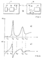
- Fig. 1 shows schematically an example of an RFID system.
- the RFID system 10 has a base station 11 and at least one transponder 15 according to the invention on. With the aid of high-frequency radio signals, the base station 11 exchanges contactless and bidirectional data with the transponder (s) 15.
- the base station 11 has at least one antenna 12 for transmitting and receiving radio signals in an operating frequency range fB, a transmitting / receiving unit 13 connected to the antenna (s) for transmitting and receiving data and a control unit connected to the transmitting / receiving unit 14 for controlling the transmitting / receiving unit 13.
- the backscatter-based, passive or semi-passive transponder 15 has an antenna 16 for receiving the radio signal spectrally in the operating frequency range fB and a receiving circuit 17 connected to the antenna for demodulating the received radio signal and detecting the data contained therein.
- the receiving circuit 17 is part of an integrated circuit (IC), not shown in FIG. an application specific integrated circuit (ASIC) or an application specific standard product (ASSP), which also regularly has a memory for storing the data required to identify the corresponding items.
- the transponder 15 or integrated circuit includes other components not shown in FIG. a sensor for temperature determination. Such transponders are also referred to as "remote sensors”.
- the operating frequency range fB is in the UHF frequency band, in a frequency range between about 840 MHz and about 960 MHz.
- the operating frequency range in the almost worldwide available ISM band (industrial, scientific, medical) range between 2.4 and 2.5 GHz.
- Other alternative operating frequency ranges are 315 MHz, 433 MHz and 5.8 GHz, respectively.
- the reading operation is aiming for ranges of approx. 5m for the European market (500 mW ERP) and approx. 11m for the USA (4 W EIRP) ,
- the integrated receiving circuit 17 has a complex-valued input impedance Z1 with a real part (effective resistance) R1 and an imaginary part (reactance) X1.
- the effective resistance R1 is hereby preferably relatively small in order to minimize power losses. Since integrated inductors would take relatively large chip areas, the reactance is X1 regularly capacitive (X1 ⁇ 0) and, in particular for small values of the effective resistance R1, greater in magnitude than the effective resistance:
- Integrated receiving circuits 17 developed by the applicant have input impedances Z1 with effective resistances R1 in the range of approximately 4... 35 ohms and capacitive reactances X1 whose absolute values are above approximately 150 ohms.
- ) clearly exceeds the real part (R1) (
- the magnitude of the capacitive reactances X1 increases further.
- the antenna 16 of the transponder 15 comprises two antenna branches, which extend spirally outward from a central region in which the antenna branches are connectable to the integrated receiving circuit 17.
- Embodiments of the antenna according to the invention are described below with reference to Figures 3 and 4.
- Fig. 2 shows schematically the frequency response of the input impedance Z2 of an antenna with two spiral branches.
- the frequency response of the input impedance Z2 is shown here over a frequency range which is significantly wider than the above-mentioned range between approximately 840 and 960 MHz.
- the effective resistance R2 i. the real part of Z2
- the reactance X2 i. the imaginary part of Z2, plotted over frequency f.
- This sequence of transitions with a first, relatively slow transition from capacitive to inductive reactances, followed by a second, faster transition from inductive to capacitive reactances is qualitatively repeated even at higher frequency values.
- the lowest series resonant frequency is also referred to as the "first" series resonant frequency fs1 and the lowest parallel resonant frequency as the "first" parallel resonant frequency fp1.
- the invention is based on the idea that the curves shown in Figure 2 of the active and reactive resistance of the antenna in the horizontal direction, i. in the direction of the frequency axis to stretch by the (path) length L of the two spiral antenna branches is varied.
- the variation of the branch length L advantageously does not take place (only) in integer multiples of complete (360 degrees) revolutions of the branches around the central area, but continuously or in steps with a small increment.
- the branch length L is chosen so that one of the series resonance frequencies fs1, fs2, fs3, ... of the antenna below the operating frequency range fB and the next higher of the parallel resonance frequencies fp1, fp2, ... the antenna is above the operating frequency range.
- the "next higher” parallel resonance frequency here means the lowest of those parallel resonance frequencies that are greater than the one, below the operating frequency range, the series resonant frequency.
- the inductive input impedance Z2 of the antenna can be brought to the likewise inductive impedance Z1 'depends on many, but in particular the following boundary conditions: a) the frequency position and width of the desired operating frequency range fB, b) the value of capacitive input impedance Z1 of the receiving circuit 17 and its course in the operating frequency range, and c) the exact configuration of the antenna according to the invention (shape of the antenna branches, width of the branches, distances between the branches, realization of the antenna, etc.).
- the branch length L is chosen such that the inductive input impedance Z2 of the antenna has values approximating to the impedance Z1 'in the operating frequency range fB and coinciding with Z1' between the antenna 16 and the integrated receiving circuit 17 no separate circuit arrangement for impedance matching is required. This is possible in particular in the case of operating frequency ranges fB, which are significantly less wide than the differences fp1-fs1, fp2-fs2, etc.
- the IC can advantageously be placed directly in the central region of the antenna branches without restriction by impedance matching components, thus enabling particularly simple and inexpensive, yet powerful transponder realizations with long ranges.
- the length L of the two spiral antenna branches can be chosen such that separate impedance matching circuitry is not required between antenna 16 and integrated receive circuit 17 and yet higher ranges and broadband reception are achieved.
- Embodiments of antennas according to the invention are described below with reference to FIGS. 3 and 4 for this case.
- FIGS. 3 and 4 show exemplary embodiments of antennas according to the invention for a backscatter-based RFID transponder according to the above description of FIG. 1.
- All illustrated embodiments are planar antennas whose branches each lie in a common plane.
- the two antenna branches of each embodiment differ only by a rotation of 180 degrees from each other. They are thus designed identically in their outer form.
- the two antenna branches each comprise a thin conductive layer, e.g. of copper, silver, etc. deposited on a common substrate e.g. is formed of polyimide or on a printed circuit board.
- the integrated receiving circuit 17 (FIG. 1) of the transponder which is advantageously arranged in a central region of the respective antenna, is preferably also formed on this substrate.
- the thin conductive layer may be applied to a foil on which the integrated receiving circuit is arranged by means of flip-chip technology. The consisting of antenna and integrated receiving circuit transponder is finally attached to the object to be identified.
- the branch length L is in the illustrated embodiments each chosen so that the frequency range of about 840 MHz to about 960 MHz between the each lowest series resonant frequency fs1 and the lowest parallel resonance frequency fp1 of the antenna, resulting in respective antenna branches, which describe essentially two full revolutions (360 degrees) about the central region.
- all embodiments shown have antenna branches whose branch width W transversely to the branch changes along the branch. This change in the branch width can be carried out continuously along the branch or in steps in steps. Starting from the central region, the branch width W generally increases toward the outside.
- FIG. 3 shows in each case a top view of a first, a second and a preferred third exemplary embodiment.
- each antenna 20 has two branches 21, 22 which are identical except for rotation through 180 degrees and extend spirally outward in oval turns from a central region 23, each branch substantially rotating two turns 360 each Degree describes.
- Each of the antenna branches 21 and 22 forms an inner radial spiral 21a or 22a and an outer radial spiral 21b and 22b, respectively, which bound the respective branch.
- the radial helices 21a, 21b, 22a, 22b in this case obey a logarithmic function, which is why this type of antenna is also referred to as a logarithmic spiral antenna.
- each antenna branch 21, 22 has a branch length L along the branch and a branch width W across the branch, the branch length L being selected according to the invention as described above and the branch width W continuously changing along the branch.
- the antenna branches 21, 22 at these contact areas can be contacted directly by the integrated receiving circuit 17 of the transponder 15.
- the integrated receiving circuit 17 is arranged in the central region 23 and preferably formed on the same substrate on which the antenna branches 21, 22 are formed. This advantageously simplifies the implementation of the transponder.
- the first exemplary embodiment illustrated in FIG. 3a is characterized by relatively wide antenna branches 21, 22 whose width, starting from the central region 23, generally increases toward the outside. Along each branch, the width in each revolution increases and decreases in sections, so that there is a "periodic" increase in width. Each branch describes exactly two full 360-degree revolutions around the central area 23. In the x-direction, this antenna has an extension of about 8.3 cm, in the y-direction about 3.6 cm.
- the first exemplary embodiment has inductive input impedances Z2 with values of the effective resistance R2 between about 4 and about 37 ohms and values of the reactance X2 between about 160 and about 370 ohms.
- the input impedance Z2 is sufficiently matched to the complex conjugate values of the input impedance Z1 of the receiving circuit 17 of the transponder 15 described above with reference to FIG.
- a separate circuit arrangement for impedance matching is advantageously not required.
- the illustrated in Fig. 3b second embodiment is characterized by relatively narrow antenna branches 21, 22 which are arranged at a relatively large distance from each other.
- the width of each branch generally increases outwards, starting from the central region 23, while a "periodic increase" again results along the branch. At the outer end of the branch, the width decreases continuously.
- Each branch describes about 2.1 full 360-degree turns around the central area 23. In the x-direction, this antenna has an extension of about 6.8 cm, in the y-direction about 3.3 cm, so that the surface occupied by the antenna is advantageously smaller by approximately 25% than in the first exemplary embodiment.
- inductive input impedances Z2 with values of the effective resistance R2 between about 4 and about 16 ohms and values of reactance X2 between about 180 and about 370 ohms.
- a separate circuit arrangement for impedance matching is advantageously also not required here.
- the third embodiment shown in Fig. 3c is characterized in comparison to the first embodiment of Fig. 3a by an extension in the direction of the x-axis and a compression in the direction of the Y-axis.
- the width of each branch in turn generally increases towards the outside and periodically increases and decreases along the branch.
- Each branch describes exactly two full 360-degree turns around the central region 23 in the x-direction, this antenna has an extension of about 10 cm, in the y-direction about 1.6 cm, so that this antenna is particularly suitable for production on a belt and / or for applications in which an elongated surface is available for the antenna.
- the area occupied by this antenna is advantageously about 45% smaller than in the first embodiment.
- inductive input impedances Z2 with values of effective resistance R2 between about 4 and about 35 ohms and values of the reactance X2 between about 170 and about 400 ohms.
- a separate circuit arrangement for impedance adaptation is advantageously not required here.
- the antennas shown in FIG. 3 Due to the low steepness of the courses of the impedance over the frequency, the antennas shown in FIG. 3 have a high bandwidth.
- the bandwidth of the overall system (transponder) depends greatly on the impedance of the integrated receiving circuit, the antenna substrate carrier and the substrate on which the transponder is mounted. Applicant's investigations have revealed overall system bandwidths in excess of 30 MHz.
- each branch starting from the central area 23, increases continuously and monotonously along the branch - possibly with the exception of a slowly departing branch end analogously to FIG. 3b.
- FIG. 4 shows in a perspective view a fourth exemplary embodiment of an antenna according to the invention.
- the antenna 30 has two branches 31, 32 which are identical except for a rotation through 180 degrees and extend spirally in angular windings from a central region 33 to the outside, each branch 2.25 rotations by 360 Degree describes.
- Each of the antenna branches 31 and 32 in this case has a plurality of straight branch sections, which are arranged at angles of 90 degrees to each other.
- This type of antenna is also called a polygonal spiral antenna.
- other angles between the branch sections can be used can be provided so that almost any number of corners per full turn of a branch can be realized.
- the turns can also be rectangular instead of square.
- each antenna branch 31, 32 has a branch length L along the branch and a branch width W across the branch, wherein the branch length L has been selected according to the invention as described above and the branch width W changes along the branch.
- the antenna branches 31, 32 are connected in the central area 33 directly to the integrated receiving circuit 17 of the transponder 15.
- the integrated receiving circuit 17 is arranged in the central region 33 and preferably formed on the same substrate on which the antenna branches are formed. This simplifies the implementation of the transponder.
- the width W of the antenna branches preferably remains constant in each straight branch portion, but changes "leaps" in the corners.
- the first straight section may have a first width, the next straight section a second, larger width, and the third section a third (in comparison to the second width, in turn) greater width etc.
- the branch width of all or only certain antenna branches from the central region along the branch increase linearly.
- the antenna shown in Fig. 4 has an x / y dimension of about 7cm x 7cm.
- inductive input impedances Z2 with values of the effective resistance R2 between about 7 and about 30 ohms and values of the reactance X2 between about 100 and about 240 ohms.
- a separate circuit arrangement for impedance matching is not required.
- the present invention has been described above with reference to exemplary embodiments, it is not limited thereto, but modifiable in many ways.
- the invention is not limited to passive or semi-passive transponders, nor to the specified frequency bands, the specified impedance values of the integrated receiving circuit or the illustrated forms of the turns of the antenna branches, etc.
- the invention Rather, it can be advantageously used in a wide variety of contactless communication systems.
Landscapes
- Near-Field Transmission Systems (AREA)
Applications Claiming Priority (1)
| Application Number | Priority Date | Filing Date | Title |
|---|---|---|---|
| DE102006003717A DE102006003717A1 (de) | 2006-01-26 | 2006-01-26 | Antenne für einen rückstreubasierten RFID-Transponder |
Publications (1)
| Publication Number | Publication Date |
|---|---|
| EP1814068A1 true EP1814068A1 (fr) | 2007-08-01 |
Family
ID=37913717
Family Applications (1)
| Application Number | Title | Priority Date | Filing Date |
|---|---|---|---|
| EP07001224A Ceased EP1814068A1 (fr) | 2006-01-26 | 2007-01-20 | Antenne pour un transpondeur RFID basé sur une rétrodiffusion |
Country Status (2)
| Country | Link |
|---|---|
| EP (1) | EP1814068A1 (fr) |
| DE (1) | DE102006003717A1 (fr) |
Cited By (2)
| Publication number | Priority date | Publication date | Assignee | Title |
|---|---|---|---|---|
| DE102013217366A1 (de) | 2013-05-22 | 2014-11-27 | Dieter Neuhold | Anordnung zur Überwachung einer Position mindestens eines ersten Objektes bezüglich mindestens eines zweiten Objektes |
| CN120043646A (zh) * | 2025-04-24 | 2025-05-27 | 国网浙江省电力有限公司杭州供电公司 | 一种无源温度报警装置及天线设计方法 |
Families Citing this family (2)
| Publication number | Priority date | Publication date | Assignee | Title |
|---|---|---|---|---|
| DE102006058168B4 (de) | 2006-12-09 | 2021-05-27 | Atmel Corp. | Antenne für einen rückstreubasierten RFID-Transponder |
| DE102008041276A1 (de) | 2008-08-15 | 2010-02-18 | Evonik Degussa Gmbh | Reichweiten- und Material-optimiertes Antennendesign für eine UHF-RFID-Antenne mit an den Chip angepasster Impedanz |
Citations (2)
| Publication number | Priority date | Publication date | Assignee | Title |
|---|---|---|---|---|
| US5313216A (en) * | 1991-05-03 | 1994-05-17 | Georgia Tech Research Corporation | Multioctave microstrip antenna |
| US20040056823A1 (en) * | 2002-09-20 | 2004-03-25 | Zuk Philip C. | RFID tag wide bandwidth logarithmic spiral antenna method and system |
-
2006
- 2006-01-26 DE DE102006003717A patent/DE102006003717A1/de not_active Withdrawn
-
2007
- 2007-01-20 EP EP07001224A patent/EP1814068A1/fr not_active Ceased
Patent Citations (2)
| Publication number | Priority date | Publication date | Assignee | Title |
|---|---|---|---|---|
| US5313216A (en) * | 1991-05-03 | 1994-05-17 | Georgia Tech Research Corporation | Multioctave microstrip antenna |
| US20040056823A1 (en) * | 2002-09-20 | 2004-03-25 | Zuk Philip C. | RFID tag wide bandwidth logarithmic spiral antenna method and system |
Non-Patent Citations (1)
| Title |
|---|
| THAYSEN J ET AL: "A Logarith,ic Spiral Antenna for 0.4 to 3.8 GHz", APPLIED MICROWAVE AND WIRELESS, J.F. WHITE PUBLICATIONS, WINCHESTER, MA, US, February 2001 (2001-02-01), pages 32,34,36,38,40,42,44 - 45, XP002992391, ISSN: 1075-0207 * |
Cited By (2)
| Publication number | Priority date | Publication date | Assignee | Title |
|---|---|---|---|---|
| DE102013217366A1 (de) | 2013-05-22 | 2014-11-27 | Dieter Neuhold | Anordnung zur Überwachung einer Position mindestens eines ersten Objektes bezüglich mindestens eines zweiten Objektes |
| CN120043646A (zh) * | 2025-04-24 | 2025-05-27 | 国网浙江省电力有限公司杭州供电公司 | 一种无源温度报警装置及天线设计方法 |
Also Published As
| Publication number | Publication date |
|---|---|
| DE102006003717A1 (de) | 2007-08-09 |
Similar Documents
| Publication | Publication Date | Title |
|---|---|---|
| WO2008061800A1 (fr) | Antenne pour un transpondeur rfid basé sur une rétrodiffusion | |
| EP2036001B1 (fr) | Transpondeur comprenant une puce mémoire électronique et une antenne circulaire magnétique | |
| EP1482647B1 (fr) | Circuit pour la modulation de phase dans un transpondeur utilisant la rétro-diffusion | |
| EP0826190B1 (fr) | Carte a puce sans contact | |
| DE60126284T2 (de) | Drahtloses kommunikationsgerät und verfahren | |
| EP1805695B1 (fr) | Systeme transpondeur | |
| DE69909301T2 (de) | Verwendung für ein hochfrequenz-identifikationssystem | |
| EP1573662B1 (fr) | Transpondeur pour la transmission sans contact de donnees | |
| US20070171074A1 (en) | Antenna for a backscatter-based RFID transponder | |
| EP1336158A1 (fr) | Support de donnees sans contact | |
| WO2007140999A2 (fr) | Principe de détermination de la position d'un transpondeur dans un système RFID | |
| EP1939793B1 (fr) | Petite plaquette de détection passive RF | |
| DE60014708T2 (de) | Antenne für radiofrequenzen für ein objektabfragegerät mit einer radiofrequenzantenne und ein damit verbundener elektrischer schaltkreis | |
| EP2263194A1 (fr) | Structure d' antenne avec au moins deux bobines-antennes; composant rf pour la transmission sans contact d' énergie et de données; appareil électronique avec composant rf | |
| EP1814068A1 (fr) | Antenne pour un transpondeur RFID basé sur une rétrodiffusion | |
| EP1930980A1 (fr) | Antenne pour un transpondeur RFID à rétrodiffusion | |
| EP1966742B1 (fr) | Dispositif et procede pour le contrôle et la transmission sans fil de l'etat d'un generateur de signaux | |
| DE102008049371A1 (de) | Einrichtung mit einem RFID-Transponder in einem elektrisch leitfähigen Gegenstand und Herstellungsverfahren hierfür | |
| DE102007058277A1 (de) | Fahrzeuginsassen-Schutzvorrichtung | |
| WO2009135722A1 (fr) | Transpondeur rfid à deux interfaces | |
| EP3483774B1 (fr) | Étagère ou armoire dotée d'au moins deux clayettes ainsi qu'ensemble d'étagère ou d'armoire doté d'au moins deux étagères ou armoires | |
| EP1756758B1 (fr) | Dispositif d'emission/reception | |
| EP2738715B1 (fr) | Tube Tag | |
| EP2036006B1 (fr) | Carte à puce et procédé de fabrication d'une carte à puce | |
| EP1190369B1 (fr) | Terminal de communication |
Legal Events
| Date | Code | Title | Description |
|---|---|---|---|
| PUAI | Public reference made under article 153(3) epc to a published international application that has entered the european phase |
Free format text: ORIGINAL CODE: 0009012 |
|
| 17P | Request for examination filed |
Effective date: 20070120 |
|
| AK | Designated contracting states |
Kind code of ref document: A1 Designated state(s): AT BE BG CH CY CZ DE DK EE ES FI FR GB GR HU IE IS IT LI LT LU LV MC NL PL PT RO SE SI SK TR |
|
| AX | Request for extension of the european patent |
Extension state: AL BA HR MK YU |
|
| 17Q | First examination report despatched |
Effective date: 20080221 |
|
| AKX | Designation fees paid |
Designated state(s): DE FR |
|
| RIC1 | Information provided on ipc code assigned before grant |
Ipc: H01Q 1/36 20060101ALI20081216BHEP Ipc: H01Q 1/22 20060101ALI20081216BHEP Ipc: H01Q 9/27 20060101ALI20081216BHEP Ipc: G06K 19/077 20060101AFI20081216BHEP |
|
| STAA | Information on the status of an ep patent application or granted ep patent |
Free format text: STATUS: THE APPLICATION HAS BEEN REFUSED |
|
| 18R | Application refused |
Effective date: 20090213 |