EP1814110B1 - Informationsaufzeichnungseinrichtung und informationsaufzeichnungsverfahren und computerprogramm - Google Patents
Informationsaufzeichnungseinrichtung und informationsaufzeichnungsverfahren und computerprogramm Download PDFInfo
- Publication number
- EP1814110B1 EP1814110B1 EP05788060A EP05788060A EP1814110B1 EP 1814110 B1 EP1814110 B1 EP 1814110B1 EP 05788060 A EP05788060 A EP 05788060A EP 05788060 A EP05788060 A EP 05788060A EP 1814110 B1 EP1814110 B1 EP 1814110B1
- Authority
- EP
- European Patent Office
- Prior art keywords
- information
- border
- recording
- recording layer
- writing
- Prior art date
- Legal status (The legal status is an assumption and is not a legal conclusion. Google has not performed a legal analysis and makes no representation as to the accuracy of the status listed.)
- Expired - Lifetime
Links
Images






Classifications
-
- G—PHYSICS
- G11—INFORMATION STORAGE
- G11B—INFORMATION STORAGE BASED ON RELATIVE MOVEMENT BETWEEN RECORD CARRIER AND TRANSDUCER
- G11B7/00—Recording or reproducing by optical means, e.g. recording using a thermal beam of optical radiation by modifying optical properties or the physical structure, reproducing using an optical beam at lower power by sensing optical properties; Record carriers therefor
- G11B7/004—Recording, reproducing or erasing methods; Read, write or erase circuits therefor
- G11B7/0045—Recording
-
- G—PHYSICS
- G11—INFORMATION STORAGE
- G11B—INFORMATION STORAGE BASED ON RELATIVE MOVEMENT BETWEEN RECORD CARRIER AND TRANSDUCER
- G11B7/00—Recording or reproducing by optical means, e.g. recording using a thermal beam of optical radiation by modifying optical properties or the physical structure, reproducing using an optical beam at lower power by sensing optical properties; Record carriers therefor
- G11B7/007—Arrangement of the information on the record carrier, e.g. form of tracks, actual track shape, e.g. wobbled, or cross-section, e.g. v-shaped; Sequential information structures, e.g. sectoring or header formats within a track
-
- G—PHYSICS
- G11—INFORMATION STORAGE
- G11B—INFORMATION STORAGE BASED ON RELATIVE MOVEMENT BETWEEN RECORD CARRIER AND TRANSDUCER
- G11B20/00—Signal processing not specific to the method of recording or reproducing; Circuits therefor
- G11B20/10—Digital recording or reproducing
- G11B20/12—Formatting, e.g. arrangement of data block or words on the record carriers
-
- G—PHYSICS
- G11—INFORMATION STORAGE
- G11B—INFORMATION STORAGE BASED ON RELATIVE MOVEMENT BETWEEN RECORD CARRIER AND TRANSDUCER
- G11B20/00—Signal processing not specific to the method of recording or reproducing; Circuits therefor
- G11B20/10—Digital recording or reproducing
- G11B20/12—Formatting, e.g. arrangement of data block or words on the record carriers
- G11B20/1217—Formatting, e.g. arrangement of data block or words on the record carriers on discs
-
- G—PHYSICS
- G11—INFORMATION STORAGE
- G11B—INFORMATION STORAGE BASED ON RELATIVE MOVEMENT BETWEEN RECORD CARRIER AND TRANSDUCER
- G11B27/00—Editing; Indexing; Addressing; Timing or synchronising; Monitoring; Measuring tape travel
- G11B27/10—Indexing; Addressing; Timing or synchronising; Measuring tape travel
- G11B27/19—Indexing; Addressing; Timing or synchronising; Measuring tape travel by using information detectable on the record carrier
- G11B27/28—Indexing; Addressing; Timing or synchronising; Measuring tape travel by using information detectable on the record carrier by using information signals recorded by the same method as the main recording
- G11B27/32—Indexing; Addressing; Timing or synchronising; Measuring tape travel by using information detectable on the record carrier by using information signals recorded by the same method as the main recording on separate auxiliary tracks of the same or an auxiliary record carrier
- G11B27/327—Table of contents
- G11B27/329—Table of contents on a disc [VTOC]
-
- G—PHYSICS
- G11—INFORMATION STORAGE
- G11B—INFORMATION STORAGE BASED ON RELATIVE MOVEMENT BETWEEN RECORD CARRIER AND TRANSDUCER
- G11B7/00—Recording or reproducing by optical means, e.g. recording using a thermal beam of optical radiation by modifying optical properties or the physical structure, reproducing using an optical beam at lower power by sensing optical properties; Record carriers therefor
- G11B2007/0003—Recording, reproducing or erasing systems characterised by the structure or type of the carrier
- G11B2007/0009—Recording, reproducing or erasing systems characterised by the structure or type of the carrier for carriers having data stored in three dimensions, e.g. volume storage
- G11B2007/0013—Recording, reproducing or erasing systems characterised by the structure or type of the carrier for carriers having data stored in three dimensions, e.g. volume storage for carriers having multiple discrete layers
-
- G—PHYSICS
- G11—INFORMATION STORAGE
- G11B—INFORMATION STORAGE BASED ON RELATIVE MOVEMENT BETWEEN RECORD CARRIER AND TRANSDUCER
- G11B20/00—Signal processing not specific to the method of recording or reproducing; Circuits therefor
- G11B20/10—Digital recording or reproducing
- G11B20/12—Formatting, e.g. arrangement of data block or words on the record carriers
- G11B20/1217—Formatting, e.g. arrangement of data block or words on the record carriers on discs
- G11B2020/1218—Formatting, e.g. arrangement of data block or words on the record carriers on discs wherein the formatting concerns a specific area of the disc
- G11B2020/1227—Formatting, e.g. arrangement of data block or words on the record carriers on discs wherein the formatting concerns a specific area of the disc one layer of multilayer disc
-
- G—PHYSICS
- G11—INFORMATION STORAGE
- G11B—INFORMATION STORAGE BASED ON RELATIVE MOVEMENT BETWEEN RECORD CARRIER AND TRANSDUCER
- G11B20/00—Signal processing not specific to the method of recording or reproducing; Circuits therefor
- G11B20/10—Digital recording or reproducing
- G11B20/12—Formatting, e.g. arrangement of data block or words on the record carriers
- G11B2020/1264—Formatting, e.g. arrangement of data block or words on the record carriers wherein the formatting concerns a specific kind of data
- G11B2020/1265—Control data, system data or management information, i.e. data used to access or process user data
- G11B2020/1277—Control data, system data or management information, i.e. data used to access or process user data for managing gaps between two recordings, e.g. control data in linking areas, run-in or run-out fields, guard or buffer zones
-
- G—PHYSICS
- G11—INFORMATION STORAGE
- G11B—INFORMATION STORAGE BASED ON RELATIVE MOVEMENT BETWEEN RECORD CARRIER AND TRANSDUCER
- G11B20/00—Signal processing not specific to the method of recording or reproducing; Circuits therefor
- G11B20/10—Digital recording or reproducing
- G11B20/12—Formatting, e.g. arrangement of data block or words on the record carriers
- G11B2020/1264—Formatting, e.g. arrangement of data block or words on the record carriers wherein the formatting concerns a specific kind of data
- G11B2020/1288—Formatting by padding empty spaces with dummy data, e.g. writing zeroes or random data when de-icing optical discs
-
- G—PHYSICS
- G11—INFORMATION STORAGE
- G11B—INFORMATION STORAGE BASED ON RELATIVE MOVEMENT BETWEEN RECORD CARRIER AND TRANSDUCER
- G11B20/00—Signal processing not specific to the method of recording or reproducing; Circuits therefor
- G11B20/10—Digital recording or reproducing
- G11B20/12—Formatting, e.g. arrangement of data block or words on the record carriers
- G11B2020/1291—Formatting, e.g. arrangement of data block or words on the record carriers wherein the formatting serves a specific purpose
- G11B2020/1294—Increase of the access speed
- G11B2020/1297—Increase of the access speed wherein the focus is on the write access speed
-
- G—PHYSICS
- G11—INFORMATION STORAGE
- G11B—INFORMATION STORAGE BASED ON RELATIVE MOVEMENT BETWEEN RECORD CARRIER AND TRANSDUCER
- G11B2220/00—Record carriers by type
- G11B2220/20—Disc-shaped record carriers
- G11B2220/21—Disc-shaped record carriers characterised in that the disc is of read-only, rewritable, or recordable type
-
- G—PHYSICS
- G11—INFORMATION STORAGE
- G11B—INFORMATION STORAGE BASED ON RELATIVE MOVEMENT BETWEEN RECORD CARRIER AND TRANSDUCER
- G11B2220/00—Record carriers by type
- G11B2220/20—Disc-shaped record carriers
- G11B2220/21—Disc-shaped record carriers characterised in that the disc is of read-only, rewritable, or recordable type
- G11B2220/215—Recordable discs
- G11B2220/216—Rewritable discs
-
- G—PHYSICS
- G11—INFORMATION STORAGE
- G11B—INFORMATION STORAGE BASED ON RELATIVE MOVEMENT BETWEEN RECORD CARRIER AND TRANSDUCER
- G11B2220/00—Record carriers by type
- G11B2220/20—Disc-shaped record carriers
- G11B2220/21—Disc-shaped record carriers characterised in that the disc is of read-only, rewritable, or recordable type
- G11B2220/215—Recordable discs
- G11B2220/218—Write-once discs
-
- G—PHYSICS
- G11—INFORMATION STORAGE
- G11B—INFORMATION STORAGE BASED ON RELATIVE MOVEMENT BETWEEN RECORD CARRIER AND TRANSDUCER
- G11B2220/00—Record carriers by type
- G11B2220/20—Disc-shaped record carriers
- G11B2220/23—Disc-shaped record carriers characterised in that the disc has a specific layer structure
- G11B2220/235—Multilayer discs, i.e. multiple recording layers accessed from the same side
-
- G—PHYSICS
- G11—INFORMATION STORAGE
- G11B—INFORMATION STORAGE BASED ON RELATIVE MOVEMENT BETWEEN RECORD CARRIER AND TRANSDUCER
- G11B2220/00—Record carriers by type
- G11B2220/20—Disc-shaped record carriers
- G11B2220/23—Disc-shaped record carriers characterised in that the disc has a specific layer structure
- G11B2220/235—Multilayer discs, i.e. multiple recording layers accessed from the same side
- G11B2220/237—Multilayer discs, i.e. multiple recording layers accessed from the same side having exactly two recording layers
-
- G—PHYSICS
- G11—INFORMATION STORAGE
- G11B—INFORMATION STORAGE BASED ON RELATIVE MOVEMENT BETWEEN RECORD CARRIER AND TRANSDUCER
- G11B2220/00—Record carriers by type
- G11B2220/20—Disc-shaped record carriers
- G11B2220/25—Disc-shaped record carriers characterised in that the disc is based on a specific recording technology
- G11B2220/2537—Optical discs
-
- G—PHYSICS
- G11—INFORMATION STORAGE
- G11B—INFORMATION STORAGE BASED ON RELATIVE MOVEMENT BETWEEN RECORD CARRIER AND TRANSDUCER
- G11B2220/00—Record carriers by type
- G11B2220/20—Disc-shaped record carriers
- G11B2220/25—Disc-shaped record carriers characterised in that the disc is based on a specific recording technology
- G11B2220/2537—Optical discs
- G11B2220/2545—CDs
-
- G—PHYSICS
- G11—INFORMATION STORAGE
- G11B—INFORMATION STORAGE BASED ON RELATIVE MOVEMENT BETWEEN RECORD CARRIER AND TRANSDUCER
- G11B2220/00—Record carriers by type
- G11B2220/20—Disc-shaped record carriers
- G11B2220/25—Disc-shaped record carriers characterised in that the disc is based on a specific recording technology
- G11B2220/2537—Optical discs
- G11B2220/2562—DVDs [digital versatile discs]; Digital video discs; MMCDs; HDCDs
Definitions
- the present invention relates to an information recording apparatus and method, such as a DVD recorder, and a computer program.
- EP 1 722 365 A discloses an information recording apparatus capable of recording a plurality of record information onto a disc-shaped information recording medium on which at least a first recording layer and a second recording layer are laminated, said information recording apparatus comprising: a writing device capable of writing each of the plurality of record information; a writing controlling device for controlling said writing device to write each of the plurality of record information such that each of the plurality of record information bridges over the first recording layer to the second recording layer; and a border controlling device for controlling said writing device to write first border information into a recording area which is a border between the plurality of record information in the first recording layer, and to write or endure second border information (116a) in a recording area of the second recording layer, which is overlapped (see fig. 2 ) with the recording area of the first recording layer in which the first border information is written, as a recording area which is to be a border between the plurality of record information in the second recording layer.
- a border zone is recorded after information which is already recorded in a user data area.
- an information reproducing apparatus or reproduce-only equipment hereinafter merely referred to as a "player etc.”
- a player etc. such as a player and a ROM drive
- an information recording apparatus or information recording / reproducing apparatus hereinafter merely referred to as a "recorder etc.”
- the "border zone” herein is an area for buffering i.e., a buffer area to prevent an unrecorded area from adjacently lying immediately after the information already recorded in the user data area or immediately after an area in which the information is recorded, as in a lead-out area in a DVD-ROM or the like. More specifically, the border zone has a structure prepared in order to perform an additional or postscript recording method, such as a multi session in a CD-R, even on a DVD-R. Incidentally, a process of recording the border zone is generally referred to as a "border close (process)".
- the border zone By recording the border zone so as not to allow, on the DVD-R or the like, the unrecorded area to adjacently lie the information already recorded in the user data area, it is possible to perform normal control of tracking servo, with respect to a DVD-R drive in which a push-pull method is adopted as a tracking method, by using an optical pickup of a DVD-ROM reproduce-only drive in which a phase difference method is adopted.
- the presence of the border zone prevents such a situation that the optical pickup of the player etc. jumps out of the already recorded user data area into the unrecorded area which is spread on the outer circumferential side thereof.
- an information recording medium such as a CD and a DVD
- a multiple layer or multilayer type, or two-layer type (i.e. dual layer type) optical disc in which a plurality of recording layers are laminated or pasted on the same substrate, as descried in patent documents 1, 2, and the like.
- laser light for recording is focused onto a recording layer located on the front or the closest side (referred to as an "L0 layer", as occasion demands, in the application), as viewed from a laser light irradiation or emission side, to thereby record the information into the L0 layer in a rewritable method or irreversible change recording method by heat or the like.
- the laser light is focused onto a recording layer located on the rear or farther side (referred to as an "L1 layer", as occasion demands, in the application), as viewed from the laser light irradiation side, through the L0 layer and the like, to thereby record the information into the L1 layer in a rewritable method or irreversible change recording method by heat or the like.
- L1 layer a recording layer located on the rear or farther side
- the "opposite manner” herein is a recording or reproducing manner in which the directions of the track passes are opposite between the two recording layers.
- the "middle area” plays the same role as the lead-out of the single layer type optical disc, and the above-mentioned border zone.
- the "middle area” is a buffer area to prevent an unrecorded area from adjacently lying immediately after the user data area in which the information is recorded.
- the information recording medium is a two-layer type or multilayer type optical disc onto which information can be additionally recorded or written once and on which the first recording layer, e.g. an L0 layer, and the second recording layer, e.g. an L1 layer, are laminated.
- the information recording apparatus is a DVD recorder or the like, for example, which can perform the recording in a form of the additional recording or the like with respect to such an information recording medium.
- the information recording apparatus can record the plurality of record information, each of which is recorded in response to a series of recording operations, at different opportunities or at the same opportunity.
- one group of contents and a file are individually recorded as the record information at different opportunities after the ON / OFF of a main power supply while one information recording medium is loaded on one information recording apparatus, or at different opportunities after the loading, unloading, and further loading of one information recording medium among a plurality of information recording apparatus.
- one record information is written by the writing device, such as an optical pickup, so that the one record information bridges over the first recording layer to the second recording layer.
- the writing device such as an optical pickup
- the former half portion of one record information is written into an L0 layer which is one example of the first recording layer, then, a layer jump is performed, and then, the latter half portion of the one record information is written into an L1 layer which is one example of the second recording layer.
- the record information is written into a user data area, for example.
- the first border information e.g. the BI (Border-In) and the BO (Border-Out) or the like described later, is written by the writing device into the recording area which is to be a border between the plurality of record information in the first recording layer. It is better to perform the writing of the first border information after the above-mentioned writing of the record information which surely makes the border clear; however, if the border position can be predicted by the reverse calculation from the information amount of the record information to be recorded, the first border information can be written before the writing of the record information described above.
- the second border information e.g. the SBO (Superficial Border-Out) and the SBI (Superficial Border-In) or the like described later, is written by the writing device in the recording area of the second recording layer, which (i.e., the recording area of the second recording layer) is overlapped with the recording area of the first recording layer in which the first border information is written, as a recording area which is to be a border between the plurality of record information in the second recording layer.
- be overlapped with the recording area herein means that areas are in the same radial position or in the same radial area of a disc-shaped optical disc and that one lies on the other, as viewed two-dimensionally in the lamination direction of the first and second recording layers of the information recording medium. Complete overlap is preferable; however, at least partial overlap can give a proper effect explained later.
- the term "be overlapped” or the "same radial position or same radial area” herein has a concept in which it is enough if it can be identified with the term “be overlapped” or the “same radial position or same radial area", from the specification and the performance of the apparatus, in performing a recording operation by the information recording apparatus, or in performing a reproduction operation on the recorder etc. and the player etc. It includes not only a complete case of the term “be overlapped” or the "same radial position or same radial area", but also a practical case thereof. It is better to perform the writing of the second border information after the writing of the first border information; however, it is also possible to perform it before the writing of the first border information.
- the second border information has a concept in which it is enough if the second border information conceptually exists as different information from the record information in the second recording layer or if a certain recording area is assigned or allocated, not to the record information, but to the second border information, because it is possible to treat the initial or previous recoding state of the information recording medium, as the recording state of the second border information even if the writing device does not specially perform a writing operation of writing the second border information. In other words, it is enough if a recording area in the predetermined recording state is reserved as the second border information.
- the first border information recorded in the first recording layer and the second border information recorded in the second recording layer are recorded, as a pair of border information, in their respective areas which are overlapped with each other. Therefore, in the case where the additional writing processes are performed at different opportunities, it is possible to avoid the situation that the record information cannot be reproduced by the player etc., by making the record-information-recorded area in one of the first and second recording layers and making the unrecorded area in the other recording layer which is overlapped therewith, during the additional writing processes.
- the record information can be additionally recorded or written once at a different opportunity after a reproduction opportunity by the player etc., so that in this case, it is possible to avoid a waste of the recording area, such as the user data area. In addition, it does not require a long processing time as in the finalize process.
- the recording can be performed without wasting the recording area while ensuring the compatibility with the player etc. Moreover, it needs only a short processing time, necessary for the recording to ensure the compatibility with the player etc.
- the additional recording process is performed with respect to each of the plurality of record information, in an opposite manner by a unit of recording area which is divided by the border or the border zone and which is a "bordered area” described later (wherein the manner is merely referred to as an "in-zone opposite manner" hereinafter, as occasion demands).
- the first start border information e.g. the BI described later
- the second end border information e.g. the SBO described later
- the first end border information e.g. the BO described later
- the second start border information e.g. the SBI described later
- the "former half portion” and “latter half portion” of the record information do not mean a strict former half or latter half based on the middle position or center of the record information, but mean a former portion and a latter portion when the record information is divided into two so that the two portions have the same size or different sizes.
- a portion recorded into the first recording layer is the former half portion, and a portion recorded into the second recording layer is the latter half portion.
- the first start border information which is the "border-in (BI)”
- the first end border information which is the "border-out (BO)
- the first start border information indicates a data structure about from where to where the data is mainly written
- the first end border information has recorded buffer data with a length of about 0.5mm in the radial direction or has a recorded jump prohibitive flag or indicates a next border or the like.
- the second end border information which is the "superficial border-in (SBI)", making a pair of the first start border information
- the second start border information which is the "superficial border-out (SBO)" making a pair of the first end border information
- the recording can be performed without wasting the recording area while ensuring the compatibility with the player etc., on the two-layer type or multilayer type information recording medium.
- the recording can be performed without wasting the recording area while ensuring the compatibility with the player etc., and particularly, it is possible to make a more apparent effect of the compatibility and efficient recording, peculiar to the present invention, by performing the additional recording process in the "in-zone opposite manner".
- the second border controlling device controls the writing device to write buffer data or a jump prohibitive flag, as at least one portion of the first end border information, in order to prevent a writing position by the writing device from deviating to the other side through the first end border information from the end border of the first recording layer.
- the second border controlling device controls the writing device to write buffer data or a jump prohibitive flag, as at least one portion of the second start border information, in order to prevent a writing position by the writing device from deviating to the other side through the second start border information from the start border of the second recording layer.
- the first border controlling device controls the writing device to write the second end border information as a copy of the first start border information.
- the second border controlling device controls the writing device to write the second start border information as a copy of the first end border information.
- the first border controlling device controls the writing device to write the first start border information after the writing of each of the plurality of record information, and then to write or ensure the second end border information
- the second border controlling device controls the writing device to subsequently write the first end border information, and then to write or ensure the second start border information
- the first border controlling device controls the writing device to write the first start border information into a lead-in area disposed in the first recording layer, as the one side of the start border in the first recording layer, and to write or ensure the second end border information in a lead-out area disposed in the second recording layer, with respect to first record information out of the plurality of record information.
- the first start border information (e.g. the BI) related to the first record information is written into the lead-in area and the second end border information (e.g. the SBO) related to the first record information is written into the lead-out area, so that it is possible to use a recording area without wasting it while ensuring the compatibility with the player etc., in the two-layer type or multilayer type information recording medium.
- the border controlling device controls the writing device to ensure the second border information as reserved information area.
- the second border information conceptually exists as different information from the record information in the second recording layer. Then, it is also possible to record other various control information or the like into the reserved information area, and the sophistication or high functioning of the apparatus can be performed by effectively using the reserved information area.
- the writing controlling device controls the writing device to write one portion or all of each of the plurality of record information, near the second border information, as dummy data, into the second recording layer.
- the writing device under the control of the writing controlling device, one portion or all, which is near the second border information, of the record information (i.e., at least one portion adjacent to or on a near side to the second border information) as being the dummy data, is written into the second recording layer.
- the additional writing processes are performed at different opportunities, it is possible to avoid the situation that the record information cannot be reproduced by the player etc., by certainly preventing that the record-information-recorded area is made in the first recording layer and the unrecorded area is made in the second recording layer which is overlapped therewith, during the additional writing processes.
- the process of filling the area with the dummy data is unnecessary.
- the border position can be predicted by the reverse calculation from the information amount of the record information to be recorded, there is little or almost no recording area to be filled with the dummy data in the second receding layer.
- the aspect of filling the area with the dummy data is greatly useful in practice, in an application to end the recording in accordance with a recording end command, for example.
- the writing controlling device controls the writing device to write one portion of each of the plurality of record information, near the first border information, as dummy data, into the first recording layer, and to write all of each of the plurality of record information, as dummy data, into the second recording layer.
- one portion, which is near the first border information, of the record information (i.e., at least one portion adjacent to or on a near side to the second border information) as being the dummy data is written into the first recording layer.
- all of the record information as being the dummy data is written into the second recording layer.
- the recording area filled with the dummy data which is so-called a wasted recording area, is only within each unit of record information, so that it is relatively small.
- the recording can be performed without wasting the recording area while ensuring the compatibility with the player etc. Moreover, it needs only a short processing time, necessary for the recording to ensure the compatibility with the player etc.
- the information recording method of the present invention can adopt various aspects.
- the above-mentioned information recording apparatus of the present invention can be relatively easily realized as a computer reads and executes the computer program from a program storage device, such as a ROM, a CD-ROM, a DVD-ROM, and a hard disk, or as it executes the computer program after downloading the program through a communication device.
- a program storage device such as a ROM, a CD-ROM, a DVD-ROM, and a hard disk
- the computer program of the present invention can adopt various aspects.
- the information recording apparatus of the present invention it is provided with: the writing device; the writing controlling device; and the border controlling device.
- the information recording method of the present invention it is provided with: the writing controlling process; and the border controlling process. Therefore, the recording can be performed without wasting the recording area while ensuring the compatibility with the player etc.
- 100 ⁇ optical disc 101 ⁇ lead-in area, 102 ⁇ data zone, 103 ⁇ lead-out area, 104 ⁇ middle area, 105 ⁇ border zone, 105a-0 ⁇ border-out, 105b-0 ⁇ border-in, 100S ⁇ transparent substrate, 106 ⁇ bordered area, 205 ⁇ superficial border zone, 205a ⁇ superficial border-out (SBO), 205b ⁇ superficial border-in (SBI), 300 ⁇ information recording / reproducing apparatus, 306 ⁇ data input/output control device, 307 ⁇ operation control device, 310 ⁇ operation button, 311 ⁇ display panel, 351 ⁇ spindle motor, 352 ⁇ optical pickup, 353 ⁇ signal recording / reproducing device, 354 ⁇ CPU (drive control device), 355 ⁇ memory, LB ⁇ laser light
- the information recording medium targeted for recording by the information recording apparatus and method of the present invention will be discussed, together with the recording / reproduction principle thereof.
- FIG. 1(a) is a substantial plan view showing the basic structure of an optical disc having a plurality of recording areas in the embodiment of the information recording medium of the present invention
- FIG. 1(b) is a schematic cross sectional view of the optical disc and a corresponding conceptual diagram showing a recording area structure in the radial direction.
- an optical disc 100 has a recording surface on a disc main body with a diameter of about 12 cm, as is a DVD.
- the optical disc 100 is provided with: a lead-in area 101; a data area 102; and a lead-out area 103 or a middle area 104, with a center hole 1 as the center.
- a transparent substrate 100S of the optical disc 100 there are laminated recording layers and the like.
- tracks 10, such as groove tracks and land tracks are alternately placed, spirally or concentrically, with the center hole 1 as the center.
- data is divided and recorded by a unit of ECC block 11.
- the ECC block 11 is a data management unit by a pre-format address in which record information is error-correctable.
- the lead-in area 101 may be provided with: a PC (Power Calibration) area PCA for an OPC (Optimum Power Calibration) process; an RM (Recording Management) area RMA in which recording management information, is recorded; and the like.
- the PCA and the RMA may be located on the disc inner circumferential side of the lead-in area 101.
- the present invention is not particularly limited to the optical disc having these three areas.
- the lead-in area 101, the lead-out area 103 or the middle area 104 does not exist, a data structure explained below can be constructed.
- the lead-in area 101, the lead-out area 103 or the middle area 104 may be further segmentized.
- the optical disc 100 in the embodiment, as shown in FIG. 1(b) has such a structure that an L0 layer and an L1 layer, which constitute one example of the "first and second record layers" of the present invention as descried later, respectively, are laminated on the transparent substrate 100S.
- the recording / reproduction of such a two-layer type optical disc 100 the recording / reproduction in the L0 layer or the L1 layer is performed, depending on which recording layer has the focus position of laser light LB, irradiated from the lower to upper side in FIG. 1(b) .
- the optical disc 100 in the embodiment is not limited to a two-layer single sided type, i.e., a dual layer type, but may be a two-layer double sided type, i.e., a dual layer double sided type.
- the optical disc 100 in the embodiment is not limited to the optical disc having the two recording layers, as described above, but may be an optical disc of a multilayer type which has three or more layers.
- a recording / reproducing procedure, peculiar to the embodiment, of recording in an in-zone opposite manner on the two-layer type optical disc and the data structure of each layer will be discussed later.
- FIG. 2 is a conceptual view schematically showing the recording structure of the optical disc if a border zone structure in the embodiment is applied.
- FIG. 3 is a conceptual view schematically showing one example of the writing procedure thereof.
- one user data which is one example of the "record information" of the present invention, such as a series of contents and one file, is recorded into the user data area 102 (refer to FIG. 1 ) in the in-zone opposite manner, so that it is recorded in one bordered area 106 in a form of a pair of user data 102-L and user data 102-L1.
- Each bordered area 106 is bridged over both the L0 layer and the L1 layer by recording the user data in the in-zone opposite manner.
- Each bordered area 106 is divided by a border zone 105 in the L0 layer, and by a superficial border zone 205 in the L1 layer.
- the user data 102-L0 which is the former half portion of one user data area, is firstly recorded into the L0 layer, from the inner to the outer circumferential side of the optical disc 100. Then, the recording direction is reversed through a layer jump. Then, the user data 102-L1, which is the latter half portion of the one user data, is recorded into the L1 layer from the outer to the inner circumferential side of the optical disc 100.
- the former half portion and the latter half portion of the user data are separately recorded into the L0 layer and the L1 layer, respectively, in the in-zone opposite manner, as in the bordered area 106 (No.1).
- the border zone 105 which divides the L0 layer, has a BO (Border-Out) and a BI (Border-In).
- the superficial border zone 205 has a SBO (Superficial Border-Out) and a SBI (Superficial Border-In). The detailed specific example thereof will be discussed later in detail (refer to FIG .4 to FIG. 6 ).
- the BO and the BI are one example of the "first border information" of the present invention. Out of them, the BO is one example of the "first end border information” of the present invention, and the BI is one example of the "first start border information” of the present invention. Moreover, the SBO and the SBI are one example of the "second border information” of the present invention. Out of them, the SBO is one example of the "second end border information” of the present invention, and the BI is one example of the "second start border information” of the present invention.
- the superficial border zone 205 in the L1 layer is located in the same radial position or in the same radial area as that of the border zone 105 in the L0 layer. More specifically, the SBI in the L1 layer is located in the same radial position or in the same radial area as that of the BO in the L0 layer, and the SBO in the L1 layer is located in the same radial position or in the same radial area as that of the BI in the L0 layer.
- an EBI Extra BI
- a ESBO Extra SBO
- LO lead-out
- the writing onto the optical disc 100 having the data structure shown in FIG. 2 is performed in a procedure shown in FIG. 3 in the in-zone opposite manner, for example.
- the writing of the ESBO or EBI may be actually performed by ensuring (or reserving) or assigning an area for the ESBO or EBI in the LO or LI.
- the layer jump is performed again and the writing position is displaced to the outer circumferential side, to thereby write the BO into the L0 layer, and again through the layer jump, the SBI is written into the L1 layer.
- the writing of the SBI may be actually performed by ensuring or assigning an area for the SBI in the LI.
- the SBI is written into the same radial position as that of the BO.
- the writing procedure of the "circle 1" to "circle 3" the writing of one user data in the in-zone opposite manner is completed with respect to the bordered area 106 (NO. 1) at the same opportunity.
- the present invention is not limited to the writing procedure in the in-zone opposite manner shown in FIG. 3 .
- the effect of the present invention can be obtained properly.
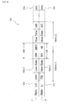
- FIG. 4 is a data structural view showing the detailed data structure of one border zone (i.e. BO and BI) in the L0 layer of the optical disc in the embodiment.
- a border zone 105-0 which is one specific example of the border zone 105, is provided with: a border-out 105a-0; and a border-in 105b-0.
- border-in 105b-0 data for control or recording management which has an information amount of the newest "5" ECC blocks is recorded.
- the data structure of the data for control or recording management is the same as that of the data for control or recording management recorded in the lead-in area.
- a BSGA Block SYNC Guard Area
- the border-out 105a-0 is further provided with: a border RMD area 105d-0; a stop block SB; three next border markers NM; and a buffer area including buffer data.
- the border RMD area 105d-0 there are copied and recorded the data for recording management, such as the newest RMD (Recording Management Data), by an information amount of "5" ECC blocks.
- the border RMD area 105d-0 can provide management information or the like for reproducing the information recorded in the border, for a DVD-ROM reproduce-only drive which cannot read the RM area in the lead-in area of a DVD-R, for example.
- the stop block SB has an information amount of "2" ECC blocks and is relatively located on the 38th and 39th from the start position of the border-out 105a-0.
- the attribute of the stop block SB area is the same as that of the lead-out area. This is to allow an optical pickup to recognize the same area as the lead-out area and to prevent the runaway of the optical pickup.
- Each of the next border markers NM has an information amount of "2" ECC blocks.
- the next border marker NM it is possible to judge whether or not there is a next border. Specifically, if there is no next border and the lead-out area has not been recorded yet, the next border marker NM of the border-out located in the last position is unrecorded. Moreover, in the border close process, for example, "00h” is recorded in each next border marker NM of the border-out located in the second last position. Furthermore, in a finalize process, for example, "00h” is padded in each next border marker NM of the last border-out, and the attribute of each next border maker NM is made the same as that of the lead-out area. Incidentally, in the case of a DVD-RW, there is no next border marker NM.
- the reserved area of the border-out 105a-0 or the reserved area of the border-in 105b-0 constitutes one example of the "buffer data" of the present invention; however, in the reserved area, there may be provided a jump prohibitive flag for preventing the optical pickup from jumping from the inner to the outer circumferential side, or from the outer to the inner circumferential side.
- a jump prohibitive flag for preventing the optical pickup from jumping from the inner to the outer circumferential side, or from the outer to the inner circumferential side.
- FIG. 5 is a data structural view showing the detailed data structure of one superficial border zone (i.e. SBI and SBO) in the L1 layer of the optical disc in the embodiment.
- SBI and SBO superficial border zone
- a superficial border zone 205-1 which is one specific example of the superficial border zone 205, is provided with: a SBO (Superficial Border-Out) 205a-1; and a SBI (Superficial Border-In) 205b-1.
- the term "superficial" of the superficial border zone 205 means apparent, surface, a feature of lying on only the outer layer of something, or insubstantial.
- the reproduction can be performed without any problem even if the content itself of the superficial border zone 205 is not particularly referred to.
- the term "superficial" has a concept that it is enough if the user data area 102 (refer to FIG. 1 ) of the L1 layer which overlaps the border zone 105 is ensured or assigned as the superficial border zone 205 without writing the user data thereinto.
- the superficial border zone 205 may be allowed to be provided as an apparent or formal border zone.
- the stop block SB having an amount of "2" ECC blocks, which is relatively located on the 38th and 39th from the start position of the SBI 205a-1, in the reserved area.
- Such a wide reserved area functions as the buffer area.
- the attribute of the stop block SB area is the same as that of the lead-out area. This is to allow an optical pickup to recognize the same area as the lead-out area and to prevent the runaway of the optical pickup.
- the SBO 205a-1 is provided with a reserved area having an amount of "6" ECC blocks, and functions as the buffer area.
- a 32kB of linking loss area is provided between the SBO 205a-1 and the SBI 205b-1.
- the reserved area of the SBO 205a-1 or the reserved area of the SBI 205b-1 constitutes one example of the "buffer data" of the present invention; however, in the reserved area, there may be provided a jump prohibitive flag for preventing the optical pickup from jumping from the inner to the outer circumferential side, or from the outer to the inner circumferential side.
- a jump prohibitive flag for preventing the optical pickup from jumping from the inner to the outer circumferential side, or from the outer to the inner circumferential side.
- the same information content of the border-out 105a-0 shown in FIG. 4 may be written into the reserved area of the SBI 205b-1.
- the same information content of the border-in 105b-0 shown in FIG. 4 i.e. the copy of it, may be written into the reserved area of the SBO 205a-1.
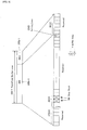
- FIG. 6(a) and FIG. 6(b) are a cross sectional view conceptually showing a situation that the BO 105a and the SBI 205b are overlapped ( FIG. 6(a) ), and a cross sectional view conceptually showing a situation that the BI 105b and the SBO 205a are overlapped ( FIG. 6(b) ).
- the SBI 205b located in the L1 layer has the BSGA at the end on the inner circumferential side thereof, as in the case of the border-in 105b-0 illustrated in FIG. 4 .
- the border zone 105a and the superficial border zone 205b are overlapped such that the BSGA is in the same radial position as that of the linking loss area (LLA) provided for the BO 105a located in the L0 layer.
- LSA linking loss area
- a COR #0, a COR #1, and so on have the same content as already illustrated in FIG. 4 .
- both the BO 105a and the SBI 205b can surely prevent the optical pickup, which is displaced from the inner circumferential side, from jumping out to the outer circumferential side.
- the SBO 205a located in the L1 layer has the linking loss area (LLA) at the end on the outer circumferential side thereof.
- the border zone 105a and the superficial border zone 205b are overlapped such that the linking loss area is in the same radial position as that of the BSGA provided for the BI 105b located in the L0 layer.
- an UPI #0, an UPI #1, and so on have the same content as already illustrated in FIG. 4 .
- both the BI 105b and the SBO 205a can surely prevent the optical pickup, which is displaced from the outer circumferential side, from jumping out to the inner circumferential side.
- both the BO to be recorded into the L0 layer and the SBI to be recorded into the L1 layer are recorded as a pair of border information, in the data areas which are overlapped with each other.
- both the BI to be recorded into the L0 layer and the SBO to be recorded into the L1 layer are recorded as a pair of border information, in the data areas which are overlapped. Therefore, in the case where the additional writing processes are performed at different opportunities, it is possible to avoid the situation that the user data cannot be reproduced by the player etc., by making the user-data-recorded area in the L0 layer and making the unrecorded area in the L1 layer which is overlapped therewith, during the additional writing processes.
- FIG. 7 is a conceptual view, having the same concept as that of FIG. 2 in a comparison example, schematically showing a recording structure related to the border zone of the optical disc.
- the optical disc in the comparison example is a two-layer type optical disc in the opposite manner to which the structure of the border zone, adopted in the single-layer type optical disc, is applied to perform recording.
- user data102 BO (Border-Out), and BI (Border-In) are recorded into bordered areas 106" (NO.1), 106" (NO. 2), and 106" (NO.3), respectively.
- the border zone 105 which forms the border or boundary of the user data 102" is provided with the BO and the BI. Following the last BO in the L1 layer, there is an unrecorded area 210.
- the unrecorded area 210 remains in the L1 layer, it is impossible to read, by the player etc., the information recorded in the already recorded user data area in the L0 layer which is spread in the same radial position as that of the unrecorded area 210. In other words, in this case, the compatibility cannot be ensured between the recorder etc. and the player etc. On the contrary, if the dummy data or the like is written into the unrecorded area 210 of the L1 layer which follows the last BO and a process like the finalize process is performed, it is possible to read the user data on the player etc.
- the border zone in the L0 layer and the superficial border zone in the L1 layer are disposed in the same radial position to make a pair, so that there is not any disadvantage that the comparison example has, and it is possible to perform the additional recording process while realizing the compatibility with the player etc.
- the recording is performed on the two-layer type optical disc in the in-zone opposite manner, it is possible to record without wasting the user data area.
- FIG. 8 is a block diagram showing the information recording / reproducing apparatus in the embodiment.
- the information recording / reproducing apparatus 300 has a function of recording the record data onto the optical disc 100 and a function of reproducing the record data recorded on the optical disc 100.
- the information recording / reproducing apparatus 300 is an apparatus for recording the information onto the optical disc 100 and reading the information recorded on the optical disc 100, under the control of a CPU (Central Processing Unit).
- a CPU Central Processing Unit
- the information recording / reproducing apparatus 300 is provided with: the optical disc 100; a spindle motor 351; an optical pickup 352; a signal recording / reproducing device 353; a CPU (drive control device) 354; a memory 355; a data input / output control device 306; an operation control device 307; an operation button 310; a display panel 311; and a bus 357.
- the former half portion of the written constitutional elements i.e., the spindle motor 351, the optical pickup 352, the signal recording / reproducing device 353, the CPU (drive control device) 354, and the memory 355 may constitute a disc drive (hereinafter referred to as a "drive", as occasion demands).
- the latter half portion of the written constitutional elements i.e., the data input / output control device 306, the operation control device 307;, the operation button 310, and the display panel 311 may constitute a host computer (hereinafter referred to as a "host”, as occasion demands).
- the CPU (drive control device) 354 and the bus 357 may constitute the communicating device of the present invention.
- the spindle motor 351 is intended to rotate and stop the optical disc 100, and operates upon accessing the optical disc. More specifically, the spindle motor 351 is constructed to rotate and stop the optical disc 100 at a predetermined speed, under spindle servo from a not-illustrated servo unit or the like.
- the optical pickup 352 is to perform the recording / reproduction with respect to the optical disc 100, and is provided with a semiconductor laser device, a lens, and the like. More specifically, the optical pickup 352 irradiates the optical disc 100 with a light beam, such as a laser beam, as reading light with a first power upon reproduction, and as writing light with a second power upon recording, with it modulated.
- a light beam such as a laser beam
- the signal recording / reproducing device 353 controls the spindle motor 351 and the optical pickup 352, to thereby perform the recording / reproduction with respect to the optical disc 100. More specifically, the signal recording / reproducing device 353 is provided with: a laser diode (LD) driver; a head amplifier; and the like, for example.
- the laser diode driver (LD driver) drives a not-illustrated semiconductor laser device located in the optical pickup 352.
- the head amplifier amplifies the output signal of the optical pickup 352, i.e. the reflective light of a light beam, and outputs the amplified signal.
- the signal recording / reproducing device 353 drives the not-illustrated semiconductor laser device located in the optical pickup 352, in order to determine an optimum laser power by the recording and reproduction processes for the OPC pattern, together with a not-illustrated timing generator or the like, under the CPU 354, upon the OPC process.
- the signal recording / reproducing device 353 constitutes one specific example of the "writing device" of the present invention, with the optical pickup 352.
- the memory 355 is used in the whole data processing and the OPC process or the like on the information recording / reproducing apparatus 300, including a buffer area for the record / reproduction data, an area used as an intermediate buffer when data is converted into the data that can be used on the signal recording / reproducing device 353, and the like. Moreover, the memory 355 is provided with: a ROM area into which a program for performing an operation as a recording device, i.e. firmware, is stored; a buffer used for compression / decompression of video data; a RAM area into which a parameter required for the operation of a program or the like is stored; and the like.
- the CPU 354 is connected to the signal recording / reproducing device 353 and the memory 355 through the bus 357, and controls the entire information recording / reproducing apparatus 300 by giving an instruction to each controlling device.
- software or firmware for operating the CPU 354 is stored in the memory 355.
- the CPU 354 constitutes one example of the "writing controlling device” and the "border controlling device” of the present invention, by virtue of the computer program recorded in the memory 355.
- the data input / output control device 306 controls the input / output of the data from the exterior with respect to the information recording / reproducing apparatus 300, to thereby perform storage to and export from the data buffer on the memory 355. If the input / output of the data is a video signal, the data input / output control device 306 compresses (encodes) the data received from the exterior in a MPEG format, for example, and outputs it to the memory 355, upon data inputting. Upon data outputting, it decompresses (decodes) the encoded data in the MPEG format or the like received from the memory 355, and outputs it to the exterior.
- the operation control device 307 receives an operation instruction and performs display with respect to the information recording / reproducing apparatus 300, and transmits an instruction by the operation button 310, such as an instruction to record or reproduce, to the CPU 354, and outputs the operation state of the information recording reproducing apparatus 300, such as during recording and during reproduction, to the display panel 311, such as a fluorescent tube.
- the operation control device 307 may be provided with a not-illustrated CPU and memory or the like, as the host computer of the present invention.
- the information recording / reproducing apparatus 300 is household equipment, such as recorder equipment for recording and reproducing video images.
- the recorder equipment records a video signal from a broadcast reception tuner and an external connection terminal, onto a disc, and outputs the video signal reproduced from the disc to external display equipment, such as a television.
- the operation as the recorder equipment is performed by executing a program stored in the memory 355, on the CPU 354.
- FIG. 9 is a flowchart showing a recording process in the embodiment.
- the optical disc 100 is loaded (step S11). Then, a seek operation is performed by the optical pickup 352 under the control of the CPU 354. Then, various management information necessary for the recording process with respect to the optical disc 100 is obtained. At the same time, after it is confirmed that the user data or the like is additionally recorded or written once, with the optical disc 100 as a DVD-R/RW, for example, the additional recording is started onto the optical disc 100. In other words, here, the writing of one user data is performed in the in-zone opposite manner, as explained with reference to FIG. 3 (step S12).
- the one user data is a group of user data having an information amount scheduled to be recorded into one border area in advance, and one TV program or show corresponds to it, for example.
- a next bordered area may be set to continue the writing, so that there is not particularly any problem. Then, during the writing, it is monitored whether or not the writing is ended in the latter half portion of the one user data with respect to the L1 layer, i.e., in the entire one user data which is scheduled (step S13).
- the writing or the like of the extra border-in (EBI) or border-in (BI) is performed (step S14). Specifically, in the case of the first user data, which is recorded for the first time on the optical disc 100, the extra border-in (EBI) is written in the lead-in area, and at the same time, the extra superficial border-out is ensured in the read-out area as an area which is overlapped with the extra border-in (EBI).
- the border-in (BI) is written in the data area of the L0 layer, and at the same time, the superficial border-out (SBO) is written in the data area of the L1 layer, in an area which is overlapped with the BI.
- such an optical disc is constructed that is a two-layer type optical disc on which the recording is performed in the in-zone opposite manner and that the border zone of the L0 layer and the superficial border zone of the L1 layer are recorded in the same radial position, as explained with reference to FIG. 1 to FIGs. 6 .
- the recording process itself can be efficiently performed by a series of writing operations, by adopting the in-zone opposite manner.
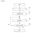
- FIG. 10 is a flowchart showing a reproduction process in the embodiment.
- the reproduction operation of the above-mentioned information recording / reproducing apparatus which belongs to the recorder etc. will be discussed; however, the reproduction operation of the player etc. is also the same.
- the reproduction can be performed without any problem by the player etc., even if the unrecorded area remains outside the bordered area which is already recorded by the recording process of FIG. 9 , in the data area; namely, even if the finalize process is not performed.
- the optical disc 100 is loaded (step S21). Then, a seek operation is performed by the optical pickup 352 under the control of the CPU 354. Then, various management information necessary for the reproduction process with respect to the optical disc 100 is obtained. Particularly in the embodiment, the reading or the like of the extra border-in (EBI) or border-in (BI) is performed. Specifically, in the case where the first user data, which is recorded for the first time on the optical disc 100, is read, the extra border-in (EBI) is read in the lead-in area. On the other hand, in the case where the second or more user data is read, the corresponding border-in (BI) is read in the data area of the L0 layer (step S22).
- EBI extra border-in
- BI border-in
- one user data which is already recorded in the in-zone opposite manner, as explained with reference to FIG. 3 is read (step S23).
- the layer jump is performed, and then, the latter half portion of the one user data in the L0 layer is read.
- the reproduction is performed without any problem on such an optical disc that is a two-layer type optical disc on which the recording is performed in the in-zone opposite manner and that the border zone of the L0 layer and the superficial border zone of the L1 layer are recorded in the same radial position, as explained with reference to FIG. 1 to FIGs. 6 .
- the reproducing apparatus is the player etc. which is not the recorder etc. which even performs the recording process, it can perform the reproduction process in the same manner as in FIG. 10 .
- the compatibility is ensured between the recorder etc. and the player etc. as shown in FIG. 8 , so that it is greatly useful.
- FIG. 11 is a conceptual view schematically showing the recording structure of the optical disc having the same concept as that of FIG. 2 , in the embodiment.
- each of the bordered areas 106 (No. 1), 106 (No. 2), and so on is filled with the user data which is scheduled to be recorded. This is to start or progress the recording after the position of the border zone is determined by the reverse calculation from the information amount of one user data to be recorded in advance, before the recording or at the initial stage of the recording.
- the data area 102 of the L1 layer which is overlapped with the recorded data area 102 of the L0 layer is not unrecorded, in each of the bordered areas 106 (No. 1), 106 (No. 2), and so on, so that it is convenient.
- the information amount of the user data to be recorded may change in some cases.
- the recording capacity of the data area 102 is wasted, only by the filling part of the unrecorded area 102D with the dummy data; however, the reproduction can be performed without any problem even by the player etc., in the same reproduction process as shown in FIG. 10 , on the optical disc 100 including the filling part with the dummy data.
- the size of the wasted data area 102 is far small.
- the additional receding process can be performed in a next bordered area even after the process of filling the unrecorded area 102D with the dummy data, so that it is dramatically advantageous.
- the process of filling the unrecorded area 102D with the dummy data is generally started from the middle of the L1 layer or performed in the entire L1 layer. However, it may be started from the middle of the L0 layer. In any case, if an unscheduledly shorten recording process is performed, it is possible to make good use of the recording capacity of the optical disc 100 as much as possible, so that it is greatly advantageous.
- the information recording / reproducing apparatus for a write-once type optical disc such as a two-layer type DVD-R
- the present invention can be applied to an information recording / reproducing apparatus for a rewritable type optical disc, such as a two-layer type DVD-RW.
- it can be also applied to an information recording / reproducing apparatus for a multiple layer type optical disc, such as a three layer type.
- it can be applied to an information recording / reproducing apparatus for a large-capacity recording medium, such as a disc which uses blue laser for recording and reproduction.
- the recording can be performed without wasting the recording area while ensuring the compatibility with the player etc., in each recording layer on the two-layer type or multilayer-type optical disc.
- the recording apparatus and method, and the computer program according to the present invention can be applied to an information recording apparatus, such as a DVD recorder. Moreover, they can be applied to an information recording apparatus or the like which is mounted on various computer equipment for consumer use or for commercial use, or which can be connected to various computer equipment.
Landscapes
- Engineering & Computer Science (AREA)
- Signal Processing (AREA)
- Optical Recording Or Reproduction (AREA)
- Signal Processing For Digital Recording And Reproducing (AREA)
- Computer And Data Communications (AREA)
Claims (11)
- Eine Informationsaufzeichnungsvorrichtung (300), die geeignet ist, eine Mehrzahl von Aufzeichnungsinformationen auf ein Informationsaufzeichnungsmedium (100) aufzuzeichnen, auf welches mindestens eine erste Aufzeichnungsschicht (L0) und eine zweite Aufzeichnungsschicht (L1) laminiert sind,
wobei die Intormationsaufzeichnungsvorrichtung aufweist:eine Schreibvorrichtung (353), die zum Schreiben von jeder aus der Mehrzahl von Aufzeichnungsinformationen geeignet ist,eine Schreibsteuerungsvorrichtung (354) zum Steuern der Schreibvorrichtung, um jede aus der Mehrzahl von Aufzeichnungsinformationen (102-L0, 102-L1) so zu schreiben, dass jede aus der Mehrzahl von Aufzeichnungsinformationen die erste Aufzeichnungsschicht zu der zweiten Aufzeichnungsschicht hin überbrückt, undeine Grenzensteuerungsvorrichtung (354) zum Steuern der Schreibvorrichtung, um erste Grenzeninformationen (BO, BI) in einen Aufzeichnungsbereich (105) zu schreiben, der eine Grenze zwischen der Mehrzahl von Aufzeichnungsinformationen in der ersten Aufzeichnungsschicht ist, und um zweite Grenzeninformationen (SBI, SBO) als einen Aufzeichnungsbereich, der eine Grenze zwischen der Mehrzahl von Aufzeichnungsinformationen in der zweiten Aufzeichnungsschicht sein soll, in einen Aufzeichnungsbereich (205) der zweiten Aufzeichnungsschicht zu schreiben oder zu sichern, der mit dem Aufzeichnungsbereich der ersten Aufzeichnungsschicht überlappt ist, in den die erste Grenzeninformation geschrieben wird,wobei das Informationsaufzeichnungsmedium scheibenförmig ist,
wobei die Schreibsteuerungsvorrichtung die Schreibvorrichtung steuert, um einen ersteren Hälftenabschnitt (102-L0) von jeder aus der Mehrzahl von Aufzeichnungsinformationen in einer Aufzeichnungsrichtung von einer Seite zu der anderen Seite von einer Innenumfangsseite und einer Außenumfangsseite des Informationsaufzeichnungsmediums aus in die erste Aufzeichnungsschicht zu schreiben, und um einen letzteren Hälftenabschnitt (102-L1) von jeder aus der Mehrzahl von Aufzeichnungsinformationen unter Umkehren der Aufzeichnungsrichtung in die zweite Aufzeichnungsschicht zu schreiben, und
wobei die Grenzensteuerungsvorrichtung aufweist:eine erste Grenzensteuerungsvorrichtung zum Steuern der Schreibvorrichtung, um eine erste Startgrenzeninformation (BI), die eine Startgrenze in der ersten Aufzeichnungsschicht der ersteren Hälftenabschnitte anzeigt, als eine der ersten Grenzeninformationen in die eine Seite der Startgrenze in der ersten Aufzeichnungsschicht zu schreiben, und um eine zweite Endgrenzeninformation (SBO), die eine Endgrenze in der zweiten Aufzeichnungsschicht des letzteren Hälftenabschnitts anzeigt, als eine der zweiten Grenzeninformationen in die zweite Aufzeichnungsschicht an einer gleichen radialen Position wie die der ersten Startgrenzeninformation vor oder nach dem Schreiben von jeder aus der Mehrzahl von Aufzeichnungsinformationen zu schreiben oder zu sichern, undeine zweite Grenzensteuerungsvorrichtung zum Steuern der Schreibvorrichtung, um eine erste Endgrenzeninformation (BO), die eine Endgrenze in der ersten Aufzeichnungsschicht des ersteren Hälftenabschnitts anzeigt, als eine andere der ersten Grenzeninformationen in die andere Seite der Endgrenze in der ersten Aufzeichnungsschicht zu schreiben, und um eine zweite Startgrenzeninformation (SBI), die eine Startgrenze in der zweiten Aufzeichnungsschicht des letzteren Hälftenabschnitts anzeigt, als eine andere der zweiten Grenzeninformationen an einer gleichen radialen Position wie die der ersten Endgrenzeninformation vor oder nach dem Schreiben von jeder aus der Mehrzahl von Aufzeichnungsinformationen in die zweite Aufzeichnungsschicht zu schreiben oder zu sichern,wobei
die erste Grenzensteuerungsvorrichtung (354) die Schreibvorrichtung (353) steuert, um die erste Startgrenzeninformation (BI) nach dem Schreiben von jeder der Mehrzahl von Aufzeichnungsinformationen (102-L0, 102-L1) zu schreiben, und um dann die zweite Endgrenzeninformation zu schreiben oder zu sichern, und
die zweite Grenzensteuerungsvorrichtung (354) die Schreibvorrichtung (353) steuert, um anschließend die erste Endgrenzeninformation (BO) zu schreiben und dann die zweite Startgrenzeninformation (SBI) zu schreiben oder zu sichern. - Die Informationsaufzeichnungsvorrichtung (300) gemäß Anspruch 1, wobei die zweite Grenzensteuerungsvorrichtung (354) die Schreibvorrichtung (353) steuert, um Pufferdaten oder eine Sprungverbotsmarkierung als mindestens einen Abschnitt der ersten Startgrenzeninformation zu schreiben, um zu verhindern, dass eine Schreibposition der Schreibvorrichtung zu der anderen Seite hin durch die erste Endgrenzeninformation (BO) von der Endgrenze der ersten Aufzeichnungsschicht abweicht.
- Die Informationsaufzeichnungsvorrichtung (300) gemäß Anspruch 1, wobei die zweite Grenzensteuerungsvorrichtung (354) die Schreibvorrichtung steuert, um Pufferdaten oder eine Sprungverbotsmarkierung als mindestens einen Abschnitt der zweiten Startgrenzeninformation zu schreiben, um zu verhindern, dass eine Schreibposition der Schreibvorrichtung zu der anderen Seite hin durch die zweite Startgrenzeninformation (SBI) von der Startgrenze der zweiten Aufzeichnungsschicht abweicht.
- Die Informationsaufzeichnungsvorrichtung (300) gemäß Anspruch 1, wobei die erste Grenzensteuerungsvorrichtung (354) die Schreibvorrichtung (353) steuert, um die zweite Endgrenzeninformation als eine Kopie der ersten Startgrenzeninformation zu schreiben.
- Die Informationsaufzeichnungsvorrichtung (300) gemäß Anspruch 1, wobei die zweite Grenzensteuerungsvorrichtung (354) die Schreibvorrichtung (353) steuert, um die zweite Startgrenzeninformation als eine Kopie der ersten Endgrenzeninformation zu schreiben.
- Die Informationsaufzeichnungsvorrichtung (300) gemäß Anspruch 1, wobei die erste Grenzensteuerungsvorrichtung (354) die Schreibvorrichtung (353) steuert, um die erste Startgrenzeninformation als die eine Seite der Startgrenze (BI) in der ersten Aufzeichnungsschicht in einen in der ersten Aufzeichnungsschicht (L0) angeordneten Lead-in-Bereich (101) zu schreiben, und um die zweite Endgrenzeninformation bezüglich der ersten Aufzeichnungsinformation aus der Mehrzahl von Aufzeichnungsinformationen in einen in der zweiten Aufzeichnungsschicht (L1) angeordneten Lead-out-Bereich (103) zu schreiben oder zu sichern.
- Die Informationsaufzeichnungsvorrichtung (300) gemäß Anspruch 1, wobei die Grenzensteuerungsvorrichtung (354) die Schreibvorrichtung (353) steuert, um die zweite Grenzeninformation als einen reservierten Informationsbereich zu sichern.
- Die Informationsaufzeichnungsvorrichtung (300) gemäß Anspruch 1, wobei die Schreibsteuerungsvorrichtung (354) die Schreibvorrichtung (353) steuert, um einen Abschnitt oder alle von jeder aus der Mehrzahl von Aufzeichnungsinformationen nahe bei der zweiten Grenzeninformation als Dummy-Daten in die zweite Aufzeichnungsschicht (L1) zu schreiben.
- Die Informationsaufzeichnungsvorrichtung (300) gemäß Anspruch 1, wobei die Schreibsteuerungsvorrichtung (354) die Schreibvorrichtung (353) steuert, um einen Abschnitt von jeder aus der Mehrzahl von Aufzeichnungsinformationen nahe bei der ersten Grenzeninformation als Dummy-Daten in die erste Aufzeichnungsschicht (L0) zu schreiben, und um alle von jeder aus der Mehrzahl von Aufzeichnungsinformationen als Dummy-Daten in die zweite Aufzeichnungsschicht (L1) zu schreiben.
- Ein Informationsaufzeichnungsverfahren in einer Informationsaufzeichnungsvorrichtung (300), die zum Aufzeichnen einer Mehrzahl von Aufzeichnungsinformationen mittels einer Schreibvorrichtung (353) auf ein Informationsaufzeichnungsmedium geeignet ist, auf welchem mindestens eine erste Aufzeichnungsschicht (L0) und eine zweite Aufzeichnungsschicht (L1) laminiert sind,
wobei das Informationsaufzeichnungsverfahren aufweist:einen Schreibsteuerungsprozess zum Steuern der Schreibvorrichtung, um jede aus der Mehrzahl von Aufzeichnungsinformationen so zu schreiben, dass jede aus der Mehrzahl von Aufzeichnungsinformationen die erste Aufzeichnungsschicht zu der zweiten Aufzeichnungsschicht hin überbrückt, undeinen Grenzensteuerungsprozess zum Steuern der Schreibvorrichtung, um eine erste Grenzeninformation in einen Aufzeichnungsbereich (105) zu schreiben, der eine Grenze zwischen der Mehrzahl von Aufzeichnungsinformationen in der ersten Aufzeichnungsschicht ist, und um eine zweite Grenzeninformation in dem Aufzeichnungsbereich (205) der zweiten Aufzeichnungsschicht, der mit dem Aufzeichnungsbereich der ersten Aufzeichnungsschicht überlappt ist, in den die erste Grenzeninformation geschrieben wird, als einen Aufzeichnungsbereich zu schreiben oder zu sichern, der eine Grenze zwischen der Mehrzahl von Aufzeichnungsinformationen in der zweiten Aufzeichnungsschicht sein soll,wobei das Informationsaufzeichnungsmedium scheibenförmig ist,
wobei der Schreibsteuerungsprozess die Schreibvorrichtung steuert, um einen ersteren Hälftenabschnitt von jeder aus der Mehrzahl von Aufzeichnungsinformationen in einer Aufzeichnungsrichtung von einer Seite zu der anderen Seite von einer Innenumfangsseite und einer Außenumfangsseite des Informationsaufzeichnungsmediums aus in die erste Aufzeichnungsschicht zu schreiben, und um einen letzteren Hälftenabschnitt von jeder aus der Mehrzahl von Aufzeichnungsinformationen unter Umkehren der Aufzeichnungsrichtung in die zweite Aufzeichnungsschicht zu schreiben, und
wobei der Grenzensteuerungsprozess aufweist:einen ersten Grenzensteuerungsprozess zum Steuern der Schreibvorrichtung, um eine erste Startgrenzeninformation (BI), die eine Startgrenze in der ersten Aufzeichnungsschicht der ersteren Hälftenabschnitte anzeigt, als eine der ersten Aufzeichnungsinformationen in die eine Seite der Startgrenze in der ersten Aufzeichnungsschicht zu schreiben, und um eine zweite Endgrenzeninformation (SBO), die eine Endgrenze in der zweiten Aufzeichnungsschicht des letzeren Hälftenabschnitts anzeigt, als eine der zweiten Grenzeninformationen an einer gleichen radialen Position wie die der ersten Startgrenzeninformation vor oder nach dem Schreiben von jeder aus der Mehrzahl von Aufzeichnungsinformationen in die zweite Aufzeichnungsschicht zu schreiben oder zu sichern, undeinen zweiten Grenzensteuerungsprozess zum Steuern der Schreibvorrichtung, um eine erste Endgrenzeninformation (BO), die eine Endgrenze in der ersten Aufzeichnungsschicht des ersteren Hälftenabschnitts anzeigt, als eine andere der ersten Grenzeninformation in die andere Seite der Endgrenze in der ersten Aufzeichnungsschicht zu schreiben, und um eine zweite Startgrenzeninformation (SBI), die eine Startgrenze in der zweiten Aufzeichnungsschicht des letzteren Hälftenabschnitts anzeigt, als eine andere der zweiten Grenzeninformationen an einer gleichen radialen Position wie die der ersten Endgrenzeninformation vor oder nach dem Schreiben von jeder aus der Mehrzahl von Aufzeichnungsinformationen in die zweite Aufzeichnungsschicht zu schreiben oder zu sichern,wobei
die erste Grenzensteuerungsvorrichtung (354) die Schreibvorrichtung (353) steuert, um die erste Startgrenzeninformation (BO) nach dem Schreiben von jeder aus der Mehrzahl von Aufzeichnungsinformationen zu schreiben, und um dann die zweite Endgrenzeninformationen (SBO) zu schreiben oder zu sichern, und
die zweite Grenzensteuerungsvorrichtung (354) die Schreibvorrichtung (353) steuert, um anschließend die erste Endgrenzeninformation (BO) zu schreiben und dann die zweite Startgrenzeninformation (SBI) zu schreiben oder zu sichern. - Ein Computerprogramm mit Befehlen, dadurch gekennzeichnet, dass das Computerprogramm für die Aufzeichnungssteuerung und zum konkreten Aufweisen eines Befehlsprogramms vorgesehen ist, das durch einen Rechner ausführbar ist, der in der Informationsaufzeichnungsvorrichtung (300) gemäß Anspruch 1 vorgesehen ist, um den Rechner als mindestens eine von der Schreibsteuerungsvorrichtung (353) und der Grenzensteuerungsvorrichtung (354) funktionieren zu lassen.
Applications Claiming Priority (2)
| Application Number | Priority Date | Filing Date | Title |
|---|---|---|---|
| JP2004291719 | 2004-10-04 | ||
| PCT/JP2005/018296 WO2006038590A1 (ja) | 2004-10-04 | 2005-10-03 | 情報記録装置及び方法、並びにコンピュータプログラム |
Publications (3)
| Publication Number | Publication Date |
|---|---|
| EP1814110A1 EP1814110A1 (de) | 2007-08-01 |
| EP1814110A4 EP1814110A4 (de) | 2009-01-21 |
| EP1814110B1 true EP1814110B1 (de) | 2010-04-14 |
Family
ID=36142663
Family Applications (1)
| Application Number | Title | Priority Date | Filing Date |
|---|---|---|---|
| EP05788060A Expired - Lifetime EP1814110B1 (de) | 2004-10-04 | 2005-10-03 | Informationsaufzeichnungseinrichtung und informationsaufzeichnungsverfahren und computerprogramm |
Country Status (9)
| Country | Link |
|---|---|
| US (1) | US8077577B2 (de) |
| EP (1) | EP1814110B1 (de) |
| JP (1) | JP4043504B2 (de) |
| KR (1) | KR100895633B1 (de) |
| CN (1) | CN101036184B (de) |
| AT (1) | ATE464637T1 (de) |
| DE (1) | DE602005020675D1 (de) |
| TW (1) | TWI348157B (de) |
| WO (1) | WO2006038590A1 (de) |
Families Citing this family (1)
| Publication number | Priority date | Publication date | Assignee | Title |
|---|---|---|---|---|
| JP2014204373A (ja) * | 2013-04-08 | 2014-10-27 | 船井電機株式会社 | 記録再生装置 |
Family Cites Families (19)
| Publication number | Priority date | Publication date | Assignee | Title |
|---|---|---|---|---|
| US5729525A (en) * | 1995-06-21 | 1998-03-17 | Matsushita Electric Industrial Co., Ltd. | Two-layer optical disk |
| JPH0916966A (ja) | 1995-06-26 | 1997-01-17 | Pioneer Electron Corp | 情報記録方法および記録再生装置 |
| WO1997015050A1 (en) | 1995-10-19 | 1997-04-24 | Matsushita Electric Industrial Co., Ltd. | Information storage medium, information reproducing method, and information reproducing apparatus |
| JPH1131357A (ja) | 1997-07-08 | 1999-02-02 | Pioneer Electron Corp | 情報データの記録方法 |
| JP3720624B2 (ja) | 1999-04-26 | 2005-11-30 | 株式会社リコー | 光ディスク記録再生装置と光ディスクの最適記録パワー値決定方法 |
| JP2001023237A (ja) | 1999-07-02 | 2001-01-26 | Pioneer Electronic Corp | 情報記録媒体 |
| JP3486165B2 (ja) | 2000-10-24 | 2004-01-13 | 株式会社東芝 | 情報記録媒体、情報記録装置、情報記録方法、情報再生装置、及び情報再生方法 |
| DE60113346T2 (de) * | 2000-07-26 | 2006-06-22 | Kabushiki Kaisha Toshiba, Kawasaki | Aufzeichnungsträger für Informationen mit einem Indexstartfeld |
| CN1246837C (zh) * | 2001-04-17 | 2006-03-22 | 松下电器产业株式会社 | 光盘制作方法、信息记录/再现方法以及信息记录/再现装置 |
| JP2003059059A (ja) | 2001-08-08 | 2003-02-28 | Hitachi Maxell Ltd | 検証用ディスク及び検証方法 |
| US6801494B2 (en) * | 2001-10-31 | 2004-10-05 | Koninklijke Philips Electronics N.V. | Multiple sections for dual-layer optical recording medium |
| JP2004295950A (ja) * | 2003-03-25 | 2004-10-21 | Ricoh Co Ltd | 光情報記録媒体、光情報記録装置、情報処理装置、光情報記録方法、プログラム及び記憶媒体 |
| JP3594243B1 (ja) * | 2003-03-25 | 2004-11-24 | 株式会社リコー | 光情報記録方法、光情報記録装置、情報処理装置、光情報記録媒体 |
| JP3584033B1 (ja) * | 2003-03-25 | 2004-11-04 | 株式会社リコー | 情報記録方法、情報記録装置、プログラム及び記憶媒体 |
| JP4633346B2 (ja) | 2003-05-12 | 2011-02-16 | ソニー株式会社 | 記録媒体、記録装置、記録方法 |
| AU2004267593A1 (en) | 2003-08-20 | 2005-03-03 | Koninklijke Philips Electronics N.V. | Method and device for recording information on a multi layer information carrier |
| WO2005076274A1 (ja) * | 2004-02-04 | 2005-08-18 | Pioneer Corporation | 情報記録媒体、情報記録装置及び方法、コンピュータプログラム |
| KR100755421B1 (ko) | 2004-03-03 | 2007-09-04 | 파이오니아 가부시키가이샤 | 정보 기록 장치 및 방법 |
| CN1910692B (zh) | 2004-09-17 | 2010-12-08 | 日本先锋公司 | 信息记录装置和方法以及信息重放装置和方法 |
-
2005
- 2005-10-03 KR KR1020077010277A patent/KR100895633B1/ko not_active Expired - Lifetime
- 2005-10-03 CN CN2005800338568A patent/CN101036184B/zh not_active Expired - Lifetime
- 2005-10-03 JP JP2006539284A patent/JP4043504B2/ja not_active Expired - Lifetime
- 2005-10-03 DE DE602005020675T patent/DE602005020675D1/de not_active Expired - Lifetime
- 2005-10-03 EP EP05788060A patent/EP1814110B1/de not_active Expired - Lifetime
- 2005-10-03 WO PCT/JP2005/018296 patent/WO2006038590A1/ja not_active Ceased
- 2005-10-03 AT AT05788060T patent/ATE464637T1/de not_active IP Right Cessation
- 2005-10-03 US US11/664,504 patent/US8077577B2/en active Active
- 2005-10-04 TW TW094134597A patent/TWI348157B/zh not_active IP Right Cessation
Also Published As
| Publication number | Publication date |
|---|---|
| EP1814110A1 (de) | 2007-08-01 |
| TWI348157B (en) | 2011-09-01 |
| WO2006038590A1 (ja) | 2006-04-13 |
| JP4043504B2 (ja) | 2008-02-06 |
| KR20070084005A (ko) | 2007-08-24 |
| US8077577B2 (en) | 2011-12-13 |
| KR100895633B1 (ko) | 2009-05-07 |
| JPWO2006038590A1 (ja) | 2008-05-15 |
| US20080062844A1 (en) | 2008-03-13 |
| CN101036184B (zh) | 2010-07-21 |
| ATE464637T1 (de) | 2010-04-15 |
| EP1814110A4 (de) | 2009-01-21 |
| CN101036184A (zh) | 2007-09-12 |
| DE602005020675D1 (de) | 2010-05-27 |
| TW200627411A (en) | 2006-08-01 |
Similar Documents
| Publication | Publication Date | Title |
|---|---|---|
| US7440375B2 (en) | Information recording device and method | |
| JP4398458B2 (ja) | 情報記録媒体、情報記録装置及び方法、並びにコンピュータプログラム | |
| CN100440333C (zh) | 信息记录装置和方法以及计算机程序 | |
| JPWO2007091620A1 (ja) | 情報記録媒体、情報記録装置及び方法、並びにコンピュータプログラム | |
| US8077577B2 (en) | Information recording device and method, and computer program | |
| US7701831B2 (en) | Information recording medium, information recording apparatus and method, and computer program | |
| JP4375677B2 (ja) | 情報記録媒体、情報記録装置及び方法、並びにコンピュータプログラム | |
| JP4442830B2 (ja) | 情報記録装置及び方法、並びにコンピュータプログラム | |
| JPWO2005093728A1 (ja) | 情報記録媒体、情報記録装置及び方法、並びにコンピュータプログラム | |
| US7948859B2 (en) | Information recording medium, information recording device and method, information reproducing device and method, information recording/reproducing device and recording method, and computer program | |
| JP4828548B2 (ja) | 情報記録装置及び方法 | |
| US8125880B2 (en) | Information recording apparatus and method, computer program | |
| JPWO2007072860A1 (ja) | 情報記録装置及び方法、コンピュータプログラム、並びに情報記録媒体 | |
| JPWO2005031720A1 (ja) | 情報記録媒体、情報記録装置及び方法 | |
| HK1095419A (en) | Information recording device and method | |
| JP2007193881A (ja) | 情報記録装置及び方法、並びにコンピュータプログラム | |
| JPWO2005093726A1 (ja) | 情報記録媒体 | |
| JP2006244680A (ja) | 情報記録装置及び方法 | |
| JP2006190476A (ja) | 情報記録媒体、情報記録装置及び方法 |
Legal Events
| Date | Code | Title | Description |
|---|---|---|---|
| PUAI | Public reference made under article 153(3) epc to a published international application that has entered the european phase |
Free format text: ORIGINAL CODE: 0009012 |
|
| 17P | Request for examination filed |
Effective date: 20070404 |
|
| AK | Designated contracting states |
Kind code of ref document: A1 Designated state(s): AT BE BG CH CY CZ DE DK EE ES FI FR GB GR HU IE IS IT LI LT LU LV MC NL PL PT RO SE SI SK TR |
|
| DAX | Request for extension of the european patent (deleted) | ||
| A4 | Supplementary search report drawn up and despatched |
Effective date: 20081229 |
|
| 17Q | First examination report despatched |
Effective date: 20090504 |
|
| GRAP | Despatch of communication of intention to grant a patent |
Free format text: ORIGINAL CODE: EPIDOSNIGR1 |
|
| GRAS | Grant fee paid |
Free format text: ORIGINAL CODE: EPIDOSNIGR3 |
|
| GRAA | (expected) grant |
Free format text: ORIGINAL CODE: 0009210 |
|
| AK | Designated contracting states |
Kind code of ref document: B1 Designated state(s): AT BE BG CH CY CZ DE DK EE ES FI FR GB GR HU IE IS IT LI LT LU LV MC NL PL PT RO SE SI SK TR |
|
| REG | Reference to a national code |
Ref country code: GB Ref legal event code: FG4D |
|
| REG | Reference to a national code |
Ref country code: CH Ref legal event code: EP |
|
| REG | Reference to a national code |
Ref country code: IE Ref legal event code: FG4D |
|
| REF | Corresponds to: |
Ref document number: 602005020675 Country of ref document: DE Date of ref document: 20100527 Kind code of ref document: P |
|
| REG | Reference to a national code |
Ref country code: NL Ref legal event code: VDEP Effective date: 20100414 |
|
| LTIE | Lt: invalidation of european patent or patent extension |
Effective date: 20100414 |
|
| PG25 | Lapsed in a contracting state [announced via postgrant information from national office to epo] |
Ref country code: LT Free format text: LAPSE BECAUSE OF FAILURE TO SUBMIT A TRANSLATION OF THE DESCRIPTION OR TO PAY THE FEE WITHIN THE PRESCRIBED TIME-LIMIT Effective date: 20100414 Ref country code: SE Free format text: LAPSE BECAUSE OF FAILURE TO SUBMIT A TRANSLATION OF THE DESCRIPTION OR TO PAY THE FEE WITHIN THE PRESCRIBED TIME-LIMIT Effective date: 20100414 Ref country code: NL Free format text: LAPSE BECAUSE OF FAILURE TO SUBMIT A TRANSLATION OF THE DESCRIPTION OR TO PAY THE FEE WITHIN THE PRESCRIBED TIME-LIMIT Effective date: 20100414 Ref country code: ES Free format text: LAPSE BECAUSE OF FAILURE TO SUBMIT A TRANSLATION OF THE DESCRIPTION OR TO PAY THE FEE WITHIN THE PRESCRIBED TIME-LIMIT Effective date: 20100725 |
|
| PG25 | Lapsed in a contracting state [announced via postgrant information from national office to epo] |
Ref country code: IS Free format text: LAPSE BECAUSE OF FAILURE TO SUBMIT A TRANSLATION OF THE DESCRIPTION OR TO PAY THE FEE WITHIN THE PRESCRIBED TIME-LIMIT Effective date: 20100814 Ref country code: AT Free format text: LAPSE BECAUSE OF FAILURE TO SUBMIT A TRANSLATION OF THE DESCRIPTION OR TO PAY THE FEE WITHIN THE PRESCRIBED TIME-LIMIT Effective date: 20100414 Ref country code: FI Free format text: LAPSE BECAUSE OF FAILURE TO SUBMIT A TRANSLATION OF THE DESCRIPTION OR TO PAY THE FEE WITHIN THE PRESCRIBED TIME-LIMIT Effective date: 20100414 Ref country code: LV Free format text: LAPSE BECAUSE OF FAILURE TO SUBMIT A TRANSLATION OF THE DESCRIPTION OR TO PAY THE FEE WITHIN THE PRESCRIBED TIME-LIMIT Effective date: 20100414 Ref country code: SI Free format text: LAPSE BECAUSE OF FAILURE TO SUBMIT A TRANSLATION OF THE DESCRIPTION OR TO PAY THE FEE WITHIN THE PRESCRIBED TIME-LIMIT Effective date: 20100414 |
|
| PG25 | Lapsed in a contracting state [announced via postgrant information from national office to epo] |
Ref country code: PL Free format text: LAPSE BECAUSE OF FAILURE TO SUBMIT A TRANSLATION OF THE DESCRIPTION OR TO PAY THE FEE WITHIN THE PRESCRIBED TIME-LIMIT Effective date: 20100414 Ref country code: CY Free format text: LAPSE BECAUSE OF FAILURE TO SUBMIT A TRANSLATION OF THE DESCRIPTION OR TO PAY THE FEE WITHIN THE PRESCRIBED TIME-LIMIT Effective date: 20100512 Ref country code: GR Free format text: LAPSE BECAUSE OF FAILURE TO SUBMIT A TRANSLATION OF THE DESCRIPTION OR TO PAY THE FEE WITHIN THE PRESCRIBED TIME-LIMIT Effective date: 20100715 |
|
| RAP2 | Party data changed (patent owner data changed or rights of a patent transferred) |
Owner name: PIONEER CORPORATION |
|
| PG25 | Lapsed in a contracting state [announced via postgrant information from national office to epo] |
Ref country code: PT Free format text: LAPSE BECAUSE OF FAILURE TO SUBMIT A TRANSLATION OF THE DESCRIPTION OR TO PAY THE FEE WITHIN THE PRESCRIBED TIME-LIMIT Effective date: 20100816 Ref country code: DK Free format text: LAPSE BECAUSE OF FAILURE TO SUBMIT A TRANSLATION OF THE DESCRIPTION OR TO PAY THE FEE WITHIN THE PRESCRIBED TIME-LIMIT Effective date: 20100414 Ref country code: EE Free format text: LAPSE BECAUSE OF FAILURE TO SUBMIT A TRANSLATION OF THE DESCRIPTION OR TO PAY THE FEE WITHIN THE PRESCRIBED TIME-LIMIT Effective date: 20100414 |
|
| PLBE | No opposition filed within time limit |
Free format text: ORIGINAL CODE: 0009261 |
|
| STAA | Information on the status of an ep patent application or granted ep patent |
Free format text: STATUS: NO OPPOSITION FILED WITHIN TIME LIMIT |
|
| PG25 | Lapsed in a contracting state [announced via postgrant information from national office to epo] |
Ref country code: RO Free format text: LAPSE BECAUSE OF FAILURE TO SUBMIT A TRANSLATION OF THE DESCRIPTION OR TO PAY THE FEE WITHIN THE PRESCRIBED TIME-LIMIT Effective date: 20100414 Ref country code: CZ Free format text: LAPSE BECAUSE OF FAILURE TO SUBMIT A TRANSLATION OF THE DESCRIPTION OR TO PAY THE FEE WITHIN THE PRESCRIBED TIME-LIMIT Effective date: 20100414 Ref country code: BE Free format text: LAPSE BECAUSE OF FAILURE TO SUBMIT A TRANSLATION OF THE DESCRIPTION OR TO PAY THE FEE WITHIN THE PRESCRIBED TIME-LIMIT Effective date: 20100414 Ref country code: SK Free format text: LAPSE BECAUSE OF FAILURE TO SUBMIT A TRANSLATION OF THE DESCRIPTION OR TO PAY THE FEE WITHIN THE PRESCRIBED TIME-LIMIT Effective date: 20100414 |
|
| 26N | No opposition filed |
Effective date: 20110117 |
|
| PG25 | Lapsed in a contracting state [announced via postgrant information from national office to epo] |
Ref country code: IT Free format text: LAPSE BECAUSE OF FAILURE TO SUBMIT A TRANSLATION OF THE DESCRIPTION OR TO PAY THE FEE WITHIN THE PRESCRIBED TIME-LIMIT Effective date: 20100414 |
|
| PG25 | Lapsed in a contracting state [announced via postgrant information from national office to epo] |
Ref country code: MC Free format text: LAPSE BECAUSE OF NON-PAYMENT OF DUE FEES Effective date: 20101031 |
|
| REG | Reference to a national code |
Ref country code: CH Ref legal event code: PL |
|
| PG25 | Lapsed in a contracting state [announced via postgrant information from national office to epo] |
Ref country code: CH Free format text: LAPSE BECAUSE OF NON-PAYMENT OF DUE FEES Effective date: 20101031 Ref country code: LI Free format text: LAPSE BECAUSE OF NON-PAYMENT OF DUE FEES Effective date: 20101031 |
|
| REG | Reference to a national code |
Ref country code: GB Ref legal event code: 746 Effective date: 20110920 |
|
| PG25 | Lapsed in a contracting state [announced via postgrant information from national office to epo] |
Ref country code: IE Free format text: LAPSE BECAUSE OF NON-PAYMENT OF DUE FEES Effective date: 20101003 |
|
| REG | Reference to a national code |
Ref country code: DE Ref legal event code: R084 Ref document number: 602005020675 Country of ref document: DE Effective date: 20110914 |
|
| PG25 | Lapsed in a contracting state [announced via postgrant information from national office to epo] |
Ref country code: LU Free format text: LAPSE BECAUSE OF NON-PAYMENT OF DUE FEES Effective date: 20101003 Ref country code: HU Free format text: LAPSE BECAUSE OF FAILURE TO SUBMIT A TRANSLATION OF THE DESCRIPTION OR TO PAY THE FEE WITHIN THE PRESCRIBED TIME-LIMIT Effective date: 20101015 Ref country code: BG Free format text: LAPSE BECAUSE OF FAILURE TO SUBMIT A TRANSLATION OF THE DESCRIPTION OR TO PAY THE FEE WITHIN THE PRESCRIBED TIME-LIMIT Effective date: 20100414 |
|
| PG25 | Lapsed in a contracting state [announced via postgrant information from national office to epo] |
Ref country code: TR Free format text: LAPSE BECAUSE OF FAILURE TO SUBMIT A TRANSLATION OF THE DESCRIPTION OR TO PAY THE FEE WITHIN THE PRESCRIBED TIME-LIMIT Effective date: 20100414 |
|
| PG25 | Lapsed in a contracting state [announced via postgrant information from national office to epo] |
Ref country code: BG Free format text: LAPSE BECAUSE OF FAILURE TO SUBMIT A TRANSLATION OF THE DESCRIPTION OR TO PAY THE FEE WITHIN THE PRESCRIBED TIME-LIMIT Effective date: 20100714 |
|
| REG | Reference to a national code |
Ref country code: FR Ref legal event code: PLFP Year of fee payment: 12 |
|
| REG | Reference to a national code |
Ref country code: FR Ref legal event code: PLFP Year of fee payment: 13 |
|
| REG | Reference to a national code |
Ref country code: FR Ref legal event code: PLFP Year of fee payment: 14 |
|
| PGFP | Annual fee paid to national office [announced via postgrant information from national office to epo] |
Ref country code: GB Payment date: 20240829 Year of fee payment: 20 |
|
| PGFP | Annual fee paid to national office [announced via postgrant information from national office to epo] |
Ref country code: FR Payment date: 20240909 Year of fee payment: 20 |
|
| PGFP | Annual fee paid to national office [announced via postgrant information from national office to epo] |
Ref country code: DE Payment date: 20240828 Year of fee payment: 20 |
|
| REG | Reference to a national code |
Ref country code: DE Ref legal event code: R071 Ref document number: 602005020675 Country of ref document: DE |
|
| REG | Reference to a national code |
Ref country code: GB Ref legal event code: PE20 Expiry date: 20251002 |
|
| REG | Reference to a national code |
Ref country code: DE Ref legal event code: R081 Ref document number: 602005020675 Country of ref document: DE Owner name: PEZYOTTA DIGITAL DATA MACHINE LTD., JP Free format text: FORMER OWNER: PIONEER CORP., TOKIO/TOKYO, JP Ref country code: DE Ref legal event code: R082 Ref document number: 602005020675 Country of ref document: DE Representative=s name: VIERING, JENTSCHURA & PARTNER MBB PATENT- UND , DE |
|
| REG | Reference to a national code |
Ref country code: GB Ref legal event code: 732E Free format text: REGISTERED BETWEEN 20260108 AND 20260114 |