EP1815108B1 - Turbine axiale a dispositif d'inhibition de survitesse - Google Patents
Turbine axiale a dispositif d'inhibition de survitesse Download PDFInfo
- Publication number
- EP1815108B1 EP1815108B1 EP05804296A EP05804296A EP1815108B1 EP 1815108 B1 EP1815108 B1 EP 1815108B1 EP 05804296 A EP05804296 A EP 05804296A EP 05804296 A EP05804296 A EP 05804296A EP 1815108 B1 EP1815108 B1 EP 1815108B1
- Authority
- EP
- European Patent Office
- Prior art keywords
- drive blades
- rotor
- cover band
- band
- blades
- Prior art date
- Legal status (The legal status is an assumption and is not a legal conclusion. Google has not performed a legal analysis and makes no representation as to the accuracy of the status listed.)
- Expired - Lifetime
Links
Images
Classifications
-
- F—MECHANICAL ENGINEERING; LIGHTING; HEATING; WEAPONS; BLASTING
- F01—MACHINES OR ENGINES IN GENERAL; ENGINE PLANTS IN GENERAL; STEAM ENGINES
- F01D—NON-POSITIVE DISPLACEMENT MACHINES OR ENGINES, e.g. STEAM TURBINES
- F01D21/00—Shutting-down of machines or engines, e.g. in emergency; Regulating, controlling, or safety means not otherwise provided for
- F01D21/02—Shutting-down responsive to overspeed
-
- F—MECHANICAL ENGINEERING; LIGHTING; HEATING; WEAPONS; BLASTING
- F01—MACHINES OR ENGINES IN GENERAL; ENGINE PLANTS IN GENERAL; STEAM ENGINES
- F01D—NON-POSITIVE DISPLACEMENT MACHINES OR ENGINES, e.g. STEAM TURBINES
- F01D11/00—Preventing or minimising internal leakage of working-fluid, e.g. between stages
- F01D11/08—Preventing or minimising internal leakage of working-fluid, e.g. between stages for sealing space between rotor blade tips and stator
- F01D11/12—Preventing or minimising internal leakage of working-fluid, e.g. between stages for sealing space between rotor blade tips and stator using a rubstrip, e.g. erodible. deformable or resiliently-biased part
-
- F—MECHANICAL ENGINEERING; LIGHTING; HEATING; WEAPONS; BLASTING
- F01—MACHINES OR ENGINES IN GENERAL; ENGINE PLANTS IN GENERAL; STEAM ENGINES
- F01D—NON-POSITIVE DISPLACEMENT MACHINES OR ENGINES, e.g. STEAM TURBINES
- F01D5/00—Blades; Blade-carrying members; Heating, heat-insulating, cooling or antivibration means on the blades or the members
- F01D5/12—Blades
- F01D5/22—Blade-to-blade connections, e.g. for damping vibrations
- F01D5/225—Blade-to-blade connections, e.g. for damping vibrations by shrouding
-
- F—MECHANICAL ENGINEERING; LIGHTING; HEATING; WEAPONS; BLASTING
- F05—INDEXING SCHEMES RELATING TO ENGINES OR PUMPS IN VARIOUS SUBCLASSES OF CLASSES F01-F04
- F05B—INDEXING SCHEME RELATING TO WIND, SPRING, WEIGHT, INERTIA OR LIKE MOTORS, TO MACHINES OR ENGINES FOR LIQUIDS COVERED BY SUBCLASSES F03B, F03D AND F03G
- F05B2240/00—Components
- F05B2240/20—Rotors
- F05B2240/33—Shrouds which are part of or which are rotating with the rotor
-
- F—MECHANICAL ENGINEERING; LIGHTING; HEATING; WEAPONS; BLASTING
- F05—INDEXING SCHEMES RELATING TO ENGINES OR PUMPS IN VARIOUS SUBCLASSES OF CLASSES F01-F04
- F05B—INDEXING SCHEME RELATING TO WIND, SPRING, WEIGHT, INERTIA OR LIKE MOTORS, TO MACHINES OR ENGINES FOR LIQUIDS COVERED BY SUBCLASSES F03B, F03D AND F03G
- F05B2260/00—Function
- F05B2260/30—Retaining components in desired mutual position
- F05B2260/301—Retaining bolts or nuts
- F05B2260/3011—Retaining bolts or nuts of the frangible or shear type
-
- F—MECHANICAL ENGINEERING; LIGHTING; HEATING; WEAPONS; BLASTING
- F05—INDEXING SCHEMES RELATING TO ENGINES OR PUMPS IN VARIOUS SUBCLASSES OF CLASSES F01-F04
- F05D—INDEXING SCHEME FOR ASPECTS RELATING TO NON-POSITIVE-DISPLACEMENT MACHINES OR ENGINES, GAS-TURBINES OR JET-PROPULSION PLANTS
- F05D2260/00—Function
- F05D2260/90—Braking
- F05D2260/902—Braking using frictional mechanical forces
Definitions
- the invention relates to an axial flow turbine motor of the type including a rotor provided with one or more peripheral rows of drive blades and a peripheral band-shaped wall element radially clamped against the tops of the drive blades, and a stator provided with inlet nozzles for a motive pressure medium and having an annular inner surface surrounding the rotor.
- a problem concerned with turbine motors is the difficulty to accomplish a simple yet reliable overspeed preventing safety device by which the rotor is prevented from reaching hazardous high speed levels where damage to equipment and operator injuries may be caused.
- a safe and suitable speed is provided by a speed governor of any suitable type, but in case of a speed governor malfunction there has to be an independently operating overspeed preventing device fitted to protect the operator and other equipment from damage and injury.
- turbine motors operate at very high speed levels it is very difficult to design a reliable and safely operating overspeed preventing device of the type comprising a mechanical speed responsive actuator and a pressure medium shut-off valve.
- Such an actuator/valve arrangement is also rather complex in design and costly to manufacture as it contains many parts which require expensive machining.
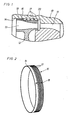
- FIGs. 1 and 2 there is shown an example illustrating the invention. Accordingly, the drawing figures show a pneumatic single stage turbine including a housing 10 with at least one pressure air nozzle 11, and a rotor 12 journalled in the housing 10 and comprising a single circumferential row of drive blades 13.
- the housing 10 is formed with an annular inner surface 14 which surrounds the rotor 12 and the rotor blades 13, and the air nozzle 11 is arranged to direct a substantially axial flow of pressure air onto the drive blades 13 at an inlet end of the latters to thereby drive the rotor 12.
- the pressure air leaves the blades 13 at an outlet end thereof at a lower pressure.
- the turbine motor according to the invention is equipped with a non-illustrated speed governor of any suitable type to keep the rotor speed at a desired level.
- a non-illustrated speed governor of any suitable type to keep the rotor speed at a desired level. This is essential for example in grinder applications where the rotation speed of a grinding tool shall be kept at a certain level for obtaining the most efficient grinding operation and the longest possible service life of the grinding tool. In such applications it also very important that the rotor speed is safely prevented from reaching any higher speed levels, since there will be a risk of grinding tool disintegration or explosion.
- the turbine In order to ensure that such high speed levels will not be reached, even if the speed governor should malfunction, the turbine has to be provided with an independently operating overspeed preventing device which will come into action only at speed levels well above the speed level normally ensured by the speed governor.
- cover band 16 On the periphery of the rotor 12, i.e. on tops of the drive blades 13, there is mounted an endless cover band 16 forming a wall element around the drive blades 13.
- This band 16 is to accomplish a favourable air flow through the rotor blades 13 to enhance the efficiency of the turbine.
- the cover band 16 In order to obtain an expanding air flow through the drive blades 13 the latters are formed with a larger radial extent at their outlet ends, which means that the cover band 16 has a larger inner diameter at the outlet end of the drive blades 13. Accordingly, the cover band 16 has a large diameter portion 19 at the outlet ends of the drive blades 13 and a reduced diameter portion 20 at the inlet ends of the drive blades 13.
- On the outside of the reduced diameter portion 20 On its outside the cover band 16 is formed with a number of circumferential ribs 17 for reducing air leakage around the rotor 12.
- the band 16 is intended to form an overspeed protective device by being formed of a suitable material and having suitable dimensions to yield under centrifugal action at rotor speed levels exceeding that normally provided by the speed governor.
- the band 16 will yield and expand in such a way that it looses its contact with the drive blades 13.
- the band 16 is displaced by the pressure difference across the drive blades 13 in the direction of the air flow such that it will get jammed between the annular surface 14 of the housing 10 and the drive blades 13.
- the band 16 will generate a braking force on the rotor 12 and prevent the latter from reaching hazardous high speed levels.
- the band 16 could be provided with weakening grooves 18 to enhance yielding of the band 16. In Fig. 2 only one groove 18 is visible, but there is at least one more groove located so as to ensure a perfect balancing of the band 16.
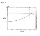
- the curve in the diagram shown in Fig. 3 illustrates how the strain related expansion of the band 16 increase as the rotation speed of the rotor 12 increases, and at a certain point Y above 10000 rad/sec the band 16 suddenly starts yielding, suitably in one or more of the grooves 18. This means that the expansion of the band 16 suddenly starts increasing more rapidly. This is indicated by a discontinuity of the curve which is quite significant and makes it possible to determine with a good accuracy the speed level at which the overspeed preventing device will come into action. This speed level could easily be separated from the speed level normally provided by the speed governor, which in this example is below 10000 rad/sek.
- the band 16 is made of an aluminium alloy and is clamped onto the drive blades 13 by a shrinking process.
- the band 16 could be made of a plastic material, and instead of shrinking the band 16 could be mounted on the rotor drive blades 13 by a press fit.
Landscapes
- Engineering & Computer Science (AREA)
- Mechanical Engineering (AREA)
- General Engineering & Computer Science (AREA)
- Turbine Rotor Nozzle Sealing (AREA)
- Connection Of Motors, Electrical Generators, Mechanical Devices, And The Like (AREA)
- Control Of Turbines (AREA)
Abstract
Claims (4)
- Moteur à turbine axiale destiné à fonctionner à un niveau de vitesse prédéterminé, comprenant un rotor (12) avec une rangée périphérique d'ailettes d'entraînement (13), un stator (10) pourvu d'une surface intérieure annulaire (14) entourant le rotor (12), et une bande de recouvrement sans fin (16) est montée sur les parties supérieures des ailettes d'entraînement (13) par action de serrage radial et forme un élément de paroi corotatif autour des ailettes d'entraînement (13),
caractérisé en ce que la bande de recouvrement (16) présente une ou plusieurs portions d'affaiblissement (18) destinées à rompre à des niveaux de vitesse au-dessus du niveau de vitesse prédéterminé auquel ladite action de serrage radial est supplantée par des forces centrifuges agissant sur la bande de recouvrement (16), ce par quoi la bande de recouvrement (16) est séparée des ailettes d'entraînement (13) et forme un moyen perturbateur de rotation entre les ailettes d'entraînement (13) et la surface intérieure (14) du stator (10). - Turbine selon la revendication 1, dans laquelle la bande de recouvrement (16) est fabriquée en une matière plastique et montée sur les ailettes d'entraînement (13) par ajustement serré.
- Turbine selon la revendication 1, dans laquelle la bande de recouvrement (16) est fabriquée en un alliage d'aluminium et est montée sur les ailettes d'entraînement (13) par un processus de frettage.
- Turbine selon l'une quelconque des revendications 1-3, dans laquelle ladite bande de recouvrement (16) présente une portion de large diamètre (19) et une portion de diamètre réduit (20), et au moins une nervure périphérique (17) est située sur ladite portion de diamètre réduit (20) et présente le même diamètre extérieur que ladite portion de large diamètre (19).
Applications Claiming Priority (2)
| Application Number | Priority Date | Filing Date | Title |
|---|---|---|---|
| SE0402850A SE528115C2 (sv) | 2004-11-23 | 2004-11-23 | Axialflödesturbin med övervarvsskyddande anordning |
| PCT/SE2005/001757 WO2006057602A1 (fr) | 2004-11-23 | 2005-11-23 | Turbine axiale a dispositif d'inhibition de survitesse |
Publications (3)
| Publication Number | Publication Date |
|---|---|
| EP1815108A1 EP1815108A1 (fr) | 2007-08-08 |
| EP1815108A4 EP1815108A4 (fr) | 2010-01-27 |
| EP1815108B1 true EP1815108B1 (fr) | 2011-05-11 |
Family
ID=33516507
Family Applications (1)
| Application Number | Title | Priority Date | Filing Date |
|---|---|---|---|
| EP05804296A Expired - Lifetime EP1815108B1 (fr) | 2004-11-23 | 2005-11-23 | Turbine axiale a dispositif d'inhibition de survitesse |
Country Status (5)
| Country | Link |
|---|---|
| US (1) | US7722323B2 (fr) |
| EP (1) | EP1815108B1 (fr) |
| JP (1) | JP5033638B2 (fr) |
| SE (1) | SE528115C2 (fr) |
| WO (1) | WO2006057602A1 (fr) |
Families Citing this family (3)
| Publication number | Priority date | Publication date | Assignee | Title |
|---|---|---|---|---|
| DE102007053135A1 (de) * | 2007-11-08 | 2009-05-14 | Mtu Aero Engines Gmbh | Gasturbinenbauteil, insbesondere Flugtriebwerksbauteil bzw. Verdichterbauteil |
| US12270347B2 (en) | 2023-04-25 | 2025-04-08 | Unison Industries, Llc | Air turbine starter with damping member |
| US12286933B2 (en) | 2023-04-25 | 2025-04-29 | Unison Industries, Llc | Air turbine starter |
Family Cites Families (11)
| Publication number | Priority date | Publication date | Assignee | Title |
|---|---|---|---|---|
| US3128989A (en) * | 1964-04-14 | Turbine overspeed control | ||
| GB629776A (en) | 1947-11-25 | 1949-09-28 | English Electric Co Ltd | Improvements in and relating to overspeed brakes for hydraulic turbine runners |
| US2962257A (en) * | 1957-03-19 | 1960-11-29 | Boeing Co | Turbine overspeed controls |
| US2987296A (en) * | 1957-12-02 | 1961-06-06 | Bendix Corp | Safety device for starter turbine |
| GB895510A (en) | 1959-07-27 | 1962-05-02 | Rotax Ltd | Air driven turbines |
| GB1299929A (en) * | 1970-04-10 | 1972-12-13 | Secr Defence | A bladed rotor for a gas turbine engine |
| US3856432A (en) * | 1973-09-27 | 1974-12-24 | Us Army | Self-governing turbine speed limiter |
| NO150135C (no) * | 1982-05-10 | 1984-08-22 | Kongsberg Vapenfab As | Anordning ved ramluftturbiner |
| GB2128685A (en) | 1982-10-06 | 1984-05-02 | Rolls Royce | Turbine overspeed limiter |
| US4507047A (en) * | 1983-02-28 | 1985-03-26 | Tech Development Inc. | Hoop turbine |
| US6312215B1 (en) * | 2000-02-15 | 2001-11-06 | United Technologies Corporation | Turbine engine windmilling brake |
-
2004
- 2004-11-23 SE SE0402850A patent/SE528115C2/sv not_active IP Right Cessation
-
2005
- 2005-11-23 JP JP2007542978A patent/JP5033638B2/ja not_active Expired - Lifetime
- 2005-11-23 WO PCT/SE2005/001757 patent/WO2006057602A1/fr not_active Ceased
- 2005-11-23 US US11/720,065 patent/US7722323B2/en active Active
- 2005-11-23 EP EP05804296A patent/EP1815108B1/fr not_active Expired - Lifetime
Also Published As
| Publication number | Publication date |
|---|---|
| JP2008521381A (ja) | 2008-06-19 |
| US20080038108A1 (en) | 2008-02-14 |
| SE528115C2 (sv) | 2006-09-05 |
| EP1815108A1 (fr) | 2007-08-08 |
| WO2006057602A1 (fr) | 2006-06-01 |
| US7722323B2 (en) | 2010-05-25 |
| EP1815108A4 (fr) | 2010-01-27 |
| SE0402850L (sv) | 2006-05-24 |
| SE0402850D0 (sv) | 2004-11-23 |
| JP5033638B2 (ja) | 2012-09-26 |
Similar Documents
| Publication | Publication Date | Title |
|---|---|---|
| RU2313672C2 (ru) | Устройство для ограничения превышения числа оборотов турбины в турбомашине | |
| EP0169801B1 (fr) | Assemblage de plaques de recouvrement d'une turbine | |
| EP0908629B1 (fr) | Compresseur ou turbine | |
| US8127525B2 (en) | System for dissipating energy in the event of a turbine shaft breaking in a gas turbine engine | |
| JP2005511949A (ja) | エアタービン・スタータ用高エネルギ粒子アレスタ | |
| US5913660A (en) | Gas turbine engine fan blade retention | |
| WO2014039188A1 (fr) | Boîtier de ventilateur tolérant vis-à-vis du frottement | |
| US3490748A (en) | Fragmentation brake for turbines | |
| CA2996454C (fr) | Turbine de moteur a turbine a gaz comprenant un element de joint d'etancheite a labyrinthe | |
| EP1815108B1 (fr) | Turbine axiale a dispositif d'inhibition de survitesse | |
| EP2071136A2 (fr) | Dispositif de freinage dans un moteur à turbine à gaz d'une turbine en cas de rupture d'arbre | |
| US8932002B2 (en) | Air turbine starter | |
| US3048364A (en) | Turbine brake | |
| JP5349000B2 (ja) | タービンエンジンホイール | |
| JP4153722B2 (ja) | 排気駆動過給機の軸流タービン | |
| KR20110115510A (ko) | 터보 기계용 인서트 및 이 인서트를 구비한 터보 기계 | |
| US4503667A (en) | Turbine overspeed limiter for turbomachines | |
| EP1726804B1 (fr) | Démarreur de turbine à air | |
| CN101649758B (zh) | 燃气涡轮发动机涡轮轴断裂时的能量耗散系统 | |
| US20160024946A1 (en) | Rotor blade dovetail with round bearing surfaces | |
| WO2013180899A1 (fr) | Joint d'étanchéité segmenté comportant des extrémités recouvrantes | |
| CN102261266A (zh) | 防止移动的涡轮机叶片 | |
| CA2000741C (fr) | Systeme de carter de turbine | |
| US20140174098A1 (en) | Turbine disc with reduced neck stress concentration | |
| WO2014096840A1 (fr) | Structure de profil aérodynamique ayant des bords de coupe de partie pointe |
Legal Events
| Date | Code | Title | Description |
|---|---|---|---|
| PUAI | Public reference made under article 153(3) epc to a published international application that has entered the european phase |
Free format text: ORIGINAL CODE: 0009012 |
|
| 17P | Request for examination filed |
Effective date: 20070620 |
|
| AK | Designated contracting states |
Kind code of ref document: A1 Designated state(s): DE FR GB IT |
|
| DAX | Request for extension of the european patent (deleted) | ||
| RBV | Designated contracting states (corrected) |
Designated state(s): DE FR GB IT |
|
| A4 | Supplementary search report drawn up and despatched |
Effective date: 20091228 |
|
| 17Q | First examination report despatched |
Effective date: 20100420 |
|
| GRAP | Despatch of communication of intention to grant a patent |
Free format text: ORIGINAL CODE: EPIDOSNIGR1 |
|
| RIC1 | Information provided on ipc code assigned before grant |
Ipc: F01D 21/04 20060101ALI20101130BHEP Ipc: F01D 21/02 20060101AFI20101130BHEP |
|
| GRAS | Grant fee paid |
Free format text: ORIGINAL CODE: EPIDOSNIGR3 |
|
| GRAA | (expected) grant |
Free format text: ORIGINAL CODE: 0009210 |
|
| AK | Designated contracting states |
Kind code of ref document: B1 Designated state(s): DE FR GB IT |
|
| REG | Reference to a national code |
Ref country code: GB Ref legal event code: FG4D |
|
| REG | Reference to a national code |
Ref country code: DE Ref legal event code: R096 Ref document number: 602005028025 Country of ref document: DE Effective date: 20110622 |
|
| PLBE | No opposition filed within time limit |
Free format text: ORIGINAL CODE: 0009261 |
|
| STAA | Information on the status of an ep patent application or granted ep patent |
Free format text: STATUS: NO OPPOSITION FILED WITHIN TIME LIMIT |
|
| 26N | No opposition filed |
Effective date: 20120214 |
|
| REG | Reference to a national code |
Ref country code: DE Ref legal event code: R097 Ref document number: 602005028025 Country of ref document: DE Effective date: 20120214 |
|
| PG25 | Lapsed in a contracting state [announced via postgrant information from national office to epo] |
Ref country code: IT Free format text: LAPSE BECAUSE OF NON-PAYMENT OF DUE FEES Effective date: 20121123 |
|
| REG | Reference to a national code |
Ref country code: FR Ref legal event code: PLFP Year of fee payment: 11 |
|
| REG | Reference to a national code |
Ref country code: FR Ref legal event code: PLFP Year of fee payment: 12 |
|
| REG | Reference to a national code |
Ref country code: FR Ref legal event code: PLFP Year of fee payment: 13 |
|
| P01 | Opt-out of the competence of the unified patent court (upc) registered |
Effective date: 20230524 |
|
| PGFP | Annual fee paid to national office [announced via postgrant information from national office to epo] |
Ref country code: DE Payment date: 20241127 Year of fee payment: 20 |
|
| PGFP | Annual fee paid to national office [announced via postgrant information from national office to epo] |
Ref country code: GB Payment date: 20241127 Year of fee payment: 20 |
|
| PGFP | Annual fee paid to national office [announced via postgrant information from national office to epo] |
Ref country code: FR Payment date: 20241128 Year of fee payment: 20 |
|
| REG | Reference to a national code |
Ref country code: DE Ref legal event code: R071 Ref document number: 602005028025 Country of ref document: DE |
|
| REG | Reference to a national code |
Ref country code: GB Ref legal event code: PE20 Expiry date: 20251122 |