EP1815135B1 - Vorrichtung zur nutzung der in strömendem wasser vorhandenen energie - Google Patents
Vorrichtung zur nutzung der in strömendem wasser vorhandenen energie Download PDFInfo
- Publication number
- EP1815135B1 EP1815135B1 EP05797876A EP05797876A EP1815135B1 EP 1815135 B1 EP1815135 B1 EP 1815135B1 EP 05797876 A EP05797876 A EP 05797876A EP 05797876 A EP05797876 A EP 05797876A EP 1815135 B1 EP1815135 B1 EP 1815135B1
- Authority
- EP
- European Patent Office
- Prior art keywords
- wave
- water
- waves
- power system
- hydroelectric power
- Prior art date
- Legal status (The legal status is an assumption and is not a legal conclusion. Google has not performed a legal analysis and makes no representation as to the accuracy of the status listed.)
- Expired - Lifetime
Links
Images


Classifications
-
- F—MECHANICAL ENGINEERING; LIGHTING; HEATING; WEAPONS; BLASTING
- F03—MACHINES OR ENGINES FOR LIQUIDS; WIND, SPRING, OR WEIGHT MOTORS; PRODUCING MECHANICAL POWER OR A REACTIVE PROPULSIVE THRUST, NOT OTHERWISE PROVIDED FOR
- F03B—MACHINES OR ENGINES FOR LIQUIDS
- F03B17/00—Other machines or engines
- F03B17/06—Other machines or engines using liquid flow with predominantly kinetic energy conversion, e.g. of swinging-flap type, "run-of-river", "ultra-low head"
-
- Y—GENERAL TAGGING OF NEW TECHNOLOGICAL DEVELOPMENTS; GENERAL TAGGING OF CROSS-SECTIONAL TECHNOLOGIES SPANNING OVER SEVERAL SECTIONS OF THE IPC; TECHNICAL SUBJECTS COVERED BY FORMER USPC CROSS-REFERENCE ART COLLECTIONS [XRACs] AND DIGESTS
- Y02—TECHNOLOGIES OR APPLICATIONS FOR MITIGATION OR ADAPTATION AGAINST CLIMATE CHANGE
- Y02E—REDUCTION OF GREENHOUSE GAS [GHG] EMISSIONS, RELATED TO ENERGY GENERATION, TRANSMISSION OR DISTRIBUTION
- Y02E10/00—Energy generation through renewable energy sources
- Y02E10/20—Hydro energy
-
- Y—GENERAL TAGGING OF NEW TECHNOLOGICAL DEVELOPMENTS; GENERAL TAGGING OF CROSS-SECTIONAL TECHNOLOGIES SPANNING OVER SEVERAL SECTIONS OF THE IPC; TECHNICAL SUBJECTS COVERED BY FORMER USPC CROSS-REFERENCE ART COLLECTIONS [XRACs] AND DIGESTS
- Y02—TECHNOLOGIES OR APPLICATIONS FOR MITIGATION OR ADAPTATION AGAINST CLIMATE CHANGE
- Y02E—REDUCTION OF GREENHOUSE GAS [GHG] EMISSIONS, RELATED TO ENERGY GENERATION, TRANSMISSION OR DISTRIBUTION
- Y02E10/00—Energy generation through renewable energy sources
- Y02E10/30—Energy from the sea, e.g. using wave energy or salinity gradient
Definitions
- the invention relates to a hydroelectric power system and to a method for transforming energy from flowing water into a different form of energy.
- a hydroelectric power system and a method for transforming energy from flowing water into a different form of energy are known in practice. Flowing water from a river is blocked by a dam. Then, the water is passed to a turbine with electricity generator where it generates electricity.
- US-A-4255066 suggests concentration of sea waves and utilization thereof for power production.
- the object of the present invention is to provide a hydroelectric power system and a method for transforming energy from flowing water in which these drawbacks are at least partially overcome or at least to create a usable alternative.
- this object is achieved by a hydroelectric power system according to claim 1 and by a method for transforming energy from flowing water according to claim 23.
- the hydroelectric power system comprises at least one wave generator, a wave booster and a wave energy transformer.
- the at least one wave generator comprises a water passage and is designed to transform at least some of the potential and/or kinetic energy of flowing water into surface waves with wave energy.
- the wave booster is designed to increase the amplitude of the surface waves in some of the water with the aid of the wave energy at least in an area where waves are exploited.
- the wave energy transformer is provided in the area where the waves are exploited and comprises a drivable conversion element for converting at least some of the energy in the boosted surface waves into a different form of energy.
- a second advantage is that some of the water can flow away past the wave energy transformer, and consequently the latter only has to be suitable for smaller quantities of water than in a hydroelectric power system which does not use the invention. As a result, it is possible to make do with a smaller and therefore less expensive wave energy transformer.
- the wave booster comprises a frame in the form of an arc of a circle, on which the at least one wave generator is provided.
- this may be an elongate wave generator which extends along at least a section of the frame in the form of an arc of a circle.
- the wave booster ensures directly at the source, during the generation of the surface waves, that a wave pattern in the form of an arc of a circle is formed, which converges as a travelling wave towards the area where the waves are exploited. On account of the shape of this wave pattern which is generated, there is in principle no need for any further measures, and consequently this is a simple way of boosting the surface waves.
- the water passage is provided with a passage control device for changing the flow of water allowed to pass through.
- the term changing the flow allowed to pass through is to be understood, for example, as encompassing both altering the quantity of water and the outflow direction. Changes of this type are a reliable way of generating a wave pattern.
- the wave generator comprises a profiled-section part which is provided in or close to the water passage.
- An increased flow velocity of the water can be realized in the water passage.
- Positioning a profiled-section part therein disturbs the water, which leads to surface waves. This phenomenon is also known as vortex shedding.
- This form of wave generation is simple since it requires few components and in principle no moving components or active control.
- the method for transforming energy from flowing water into a different form of energy comprises the following steps:
- the amplitude of the generated surface waves is increased by letting the generated surface waves converge.
- This form of wave boosting requires relatively few or limited infrastructure measures, making it a relatively inexpensive form.
- the amplitude of the generated surface waves is increased by generating a standing.wave.
- exciting the standing wave in its natural frequency it is possible to produce a wave with sufficient potential energy and pressure to be able to transform energy efficiently.
- a standing wave of this type can be successfully generated in a limited space which can be restricted, with the result that the process itself, and the associated transformation of energy, can be successfully controlled.
- the invention also relates to the use of a hydroelectric power system according to claim 33.
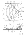
- a hydroelectric power system according to the invention is denoted overall by reference numeral 1.
- This hydroelectric power system 1 is provided in a river 2 which is delimited by a left bank 3 and right bank 4 (as seen in the downstream direction).
- a frame in the form of an arc of a circle, in the form of a dam 5, is provided in the river 2.
- the dam 5 is provided with a plurality of wave generators 6, for example in the form of an inverted siphon, as diagrammatically indicated in Fig. 2 and discussed in more detail in connection with Figs. 14 - 17 .
- the dam 5 is provided on a bed 7 of the river 2.
- the water level 8 upstream of the hydroelectric power system 1 is higher than the water level 9 downstream of the hydroelectric power system 1.
- the hydroelectric power system 1 is also provided with a wave energy transformer 10 (cf. also Fig. 27 ).
- the wave energy transformer 10 comprises an overflow basin 11, a drivable conversion element in the form of a water-driven turbine 12.
- the water-driven turbine 12 is provided in a water feed 13, which is connected to an outflow opening in the bottom of the overflow basin 11. From the water-driven turbine 12, a water discharge 14 leads to the downstream part of the river 2.
- the wave energy transformer 10 is also provided with a sloping part 15.
- the hydroelectric power system 1 may also be provided with a first side wall 18 and a second side wall 19.
- the overflow basin 11 can in this case be considered as a water discharge from the wave chamber 20.
- the damming height i.e. the difference between the first water level 8 and the second water level 9, is relatively low, for example about 1 metre.
- the wave generators 6 in the dam 5 generate travelling surface waves 22 in a way which will be explained in connection with the following figures.
- the wave generators 6 generate the waves 22 synchronously along the dam 5, which is in the form of an arc of a circle, a wave pattern which is in the form of an arc of a circle is produced and propagates such that it converges in the direction of the arrows 25.
- the height of the waves 22 will increase as the waves 22 converge. Therefore, the wave chamber 20, by virtue of the circular shape of the dam 5, functions as a wave booster.
- the optional side walls 18 and 19 in this case prevent wave energy from leaking away.
- these side walls 18 and 19 are not imperative, since the wave boosting is primarily a consequence of the waves 22 being generated in the form of an arc of a circle.
- the left and right banks 3, 4 can delimit the wave chamber 20.
- the waves 22 converge towards an area 30 where the waves are exploited, which is located in or close to the imaginary centre point of the dam 5 in the shape of an arc of a circle.
- the wave energy transformer 10 is located in the area 30 where the waves are exploited. As they approach the wave energy transformer 10, the waves 22 run onto the slope 15, with kinetic energy being transformed into potential energy and the crests of the waves 22 entering the overflow basin 11.
- the level of the overflow basin 11 is higher than the original level 8 of the river 2, so that the water in the overflow basin 11 has a higher potential energy in relative terms than at the water level 8 upstream of the hydroelectric power system 1.
- This potential energy is converted via the water feed 13, the water-driven turbine 12 and the water discharge 14 into mechanical energy, which can then be transformed into electrical energy.
- wave generator 6 variants which can be provided both as separate wave generators distributed over the width of the river 2 along a frame, or in the form of one elongate wave generator which is provided over substantially the entire length of a frame, i.e. substantially the entire width of the river 2.
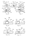
- Figs. 3 - 9 show wave generators with actively controllable passage control devices which comprise a flow rate metering unit.
- Fig. 3 shows a wave generator 110 which comprises a flow rate metering.unit in the form of a valve, in particular a vertically movable slide 111.
- the vertical slide 111 is provided displaceably in a vertical guide 112. Moving the vertical slide 111 upwards forms a water passage, in the form of a through-flow opening 113, through which a quantity of water can escape, generating a water wave 114. Subsequent closure of the vertical slide 111 produces a wave trough downstream of the slide 111, while the water is dammed upstream of the vertical slide 111.
- Fig. 4 shows a wave generator 120 which comprises a flow rate metering unit in the form of a valve, in particular a horizontally pivotable partition 121.
- the partition 121 is pivotably connected to a frame 122 along a top edge. In a first, vertical, closed position, the partition 121 dams the river water. Pivoting away the partition 121 allows through a quantity of water, resulting in the formation of a wave crest 124. Closing the partition 121 again produces a wave trough 125 which follows the wave crest.
- Fig. 5 shows a wave generator 130 which comprises a flow rate metering unit in the form of a valve, in particular a horizontally pivotable partition 131.
- a frame extends over the width of the river 2 in the form of an underwater dam 132.
- the partition 131 is connected to the underwater dam 132 by means of a pivoting connection. Pivoting it from a closed position to an open position and vice versa produces waves 134, 135.
- Fig. 6 shows a wave generator 140 which comprises a flow rate metering unit in the form of a valve, in particular a pivotable valve 141, which is connected to a frame (not shown).
- the wave generator 140 also comprises an underwater dam 142 on which a substantially L-shaped damming part 143 is provided.
- Fig..7 shows a wave generator 150 with a flow rate metering unit in the form of a valve, in particular a pivotable valve 151.
- the hinge pivot 152 of the valve. 151 extends substantially in the horizontal direction, parallel to an underwater dam 153.
- the hinge 152 is connected, in a manner which is not shown, to, for example, the banks 3, 4 of the river 2 and/or the underwater dam 153.
- a water passage 154 is alternately opened and closed, so as to form a wave crest 155 and wave trough 156.
- Fig. 8 shows a wave generator 160 which comprises a flow rate metering unit in the form of an expandable dam 161.
- a water passage 162 is formed'above the expandable dam 161.
- river water flows through the passage 162, with a wave crest 164 being formed downstream of the dam 161.
- At least partially expanding the expandable dam 161 to an expanded state as shown in Fig. 8 in which the expandable dam 161 extends above the water level, closes the water passage 162 and produces a wave trough 165 downstream of the expandable dam 161.
- Fig. 10 shows a wave generator 170 which comprises a dam 171 in which a split-shaped opening 172 is provided.
- Fig. 11 likewise shows a wave generator 180 which acts on the basis of vortex shedding.
- An underwater dam 181 delimits a water passage 182 at its top side.
- a profiled-section part 183 is provided in.this water passage 182. Vortex shedding takes place downstream of this profiled-section part 183, resulting in the formation of waves 184.
- the profiled-section part 183 shown is provided in a fixed position. In an alternative embodiment, the profiled-section part 183 may oscillate or vibrate to promote the vortex shedding.
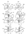
- Fig. 12 shows a wave generator 190 with an overflow dam 191.
- the overflow dam 191 delimits a water passage 192.
- the overflow dam 191 has a damming side 193 and a low side 194.
- the overflow dam 191 has an actively controllable outflow direction control unit which comprises a dam passage 195.
- Fig. 13 shows a situation in which air is being supplied through the dam passage 195 to the low side of the overflow dam 191 or in which no passage of air is taking place.
- Fig. 13 shows a situation in which air is being supplied through the dam passage 195 to the low side of the overflow dam 191 or in which no passage of air is taking place.
- Fig. 13 shows a situation in which air is being supplied through the dam passage 195 to the low side of the overflow dam 191 or in which no passage of air is taking place.
- Fig. 13 shows a situation in which air is being supplied through the dam passage 195 to the low side of the overflow dam 191 or in which no passage of air is taking place.
- a sharp edge 197 which extends along the.top edge of the overflow dam .191
- An air pocket 198 is present between the low side of the overflow dam 191 and the water.
- the wave generator 200 comprises a water passage 201 which is in the form of an inverted siphon and is provided on top of a frame, in this case a dam 202.
- An inflow.opening 203. is located on the damming side of the dam 202, while an outflow opening 204 is located on the low side.
- the water passage 201 delimits a through flow space 205.
- a high section 206 of the through-flow space 205 is located at a higher level than the inflow opening 203 and the outflow opening 204.
- the water passage 201 forms an autonomously functioning passage control device 207 which operates as follows. In the situation shown in Fig. 14 , there is air in the high section 206. As a result, the water passage 201 only allows a relatively small quantity of water to pass through it. However, the air which.is present is entrained by the flowing water, so that the water passage 201 will ultimately be completely filled with water. At that time, the passage capacity of the water passage 201 increases greatly, with the result that a large quantity of water flows through, forming a wave crest 208 downstream of the outflow opening 204.
- the water level on the high side drops, i.e. at the location of the inflow opening 203, as shown in Fig. 16 .
- the water level locally rises again to the top of the dam 202, restoring the situation shown in Fig. 14 .
- Fig. 18 and Fig. 19 show a wave generator 210.
- the wave generator 210 like that shown in Figs. 14 to 17 , comprises a water passage 211 in the form of an inverted siphon.
- the water passage 211 is provided on a frame in the form of a dam 212 and has an inflow opening 213 and an outflow opening 214.
- the water passage 201 formed an autonomously functioning passage control device, the water passage. 211 is actively controllable.
- a gas passage opening 216 is provided in a.high section. 215 of the water passage 211.
- the gas passage leading to the gas passage opening 216 can be opened and closed by means of a gas valve 217.
- the gas passage valve 217 When the gas passage valve 217 is closed ( Fig. 18 ), the water passage 211 is at its maximum through-flow capacity. Opening the gas valve 217 causes air to enter the high section 215 and stops the passage of water or at least reduces it ( Fig. 19 ).
- the wave generators as described in connection with Figures 3 to 19 are provided on or integrated with a frame, for example a dam, which extends across the width of the river 2.
- This frame may be in the form of an arc of a circle, as shown in. Fig. 1 .
- the wave generator in question is a wave generator which extends over substantially the entire length of the frame, or if a plurality of wave generators are provided operating synchronously, for example as a result of a phase control device, the result will be the formation of a converging wave pattern in the form of an arc of a circle as described in connection with Fig. 1 .
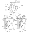
- Fig. 20 shows a hydroelectric power system 301 provided in a river 302 with banks 303 and 304.
- a straight, elongate frame in the form of a straight dam 305 extends from the left bank 303 to the right bank 304.
- a plurality of wave generators 306 are provided on the dam 305.
- a wave booster comprises a wave chamber 320,'.which is delimited by the straight dam 305, the banks 303 and 304 and a wave energy transformer (not shown).
- the wave booster also comprises a phase control device (not shown) which is connected to the plurality of wave generators, for matching the phases of the waves 322 formed by the wave generators 306.
- a phase control device of this type can match the phases of the wave boosters electrically, electronically, mechanically, hydraulically or in some other way.
- A.phase shift during the generation of the waves 322 produces a converging wave pattern in the form of an arc of a circle, with the waves 322 converging towards an area .330 where the waves are exploited and where the wave energy transformer. (not shown) is provided.
- Fig. 21 shows an embodiment of a hydroelectric power system 401 according to the invention, provided in a river .402 which is delimited by banks 403 and 404.
- a frame 405 with a wave generator is provided in the river. This may be one of the wave generators which has been described in connection with the previous figures.
- a beaker element 407 and a wave energy transformer 410 are provided in the river.
- the breaker element 407 is designed to change a direction of propagation of waves. In use, it is located substantially under water and forms part of a wave booster.
- the wave booster also comprises a wave chamber 420 which is delimited by the frame 405, the banks 403 and 404 and the wave energy transformer 410.
- the wave generator 405 generates waves 422 which in the first instance propagate substantially in the same...direction as the direction of flow of the river 402.
- the waves 422 which reach the breaker element 407 are broken by refraction to form a converging wave pattern 423.
- the wave height increases in the direction of the wave energy transformer 410, which is provided in an area 430 where the waves are exploited.
- Fig. 22 shows an embodiment of a hydroelectric power system 501 according to the invention, provided in a river 502 which is delimited by banks 503 and 504.
- a frame 505 with a wave generator is provided in the river. This may be one of the wave generators which has been described in connection with the previous figures.
- a plurality of breaker elements 507 and a wave energy transformer 510 are provided in the river.
- a wave booster comprises the breaker elements 507 and a wave chamber 502, which is delimited by the frame 505, the banks 503 and 504, and the wave energy converter 510.
- the breaker elements 507 extend from the bed of the river to above the water surface. Alternatively, they may also extend to close to the water surface.
- the breaker elements 507 extend substantially along an imaginary line which runs parallel to the frame 505, i.e. perpendicular to the direction of flows of the river 502. Alternatively, breaker elements may also extend in the direction of flow of the river. Openings are provided between the breaker elements 507.
- the shape, dimensions and distances between the breaker elements are adapted to the wave length of the waves generated in such a manner that wave diffraction occurs.
- the breaker elements may take various cross-sectional shapes, including cylindrical, elliptical and rectangular. In a variant, the breaker elements may extend to below the water surface for a combination of refraction and diffraction.
- the wave generator 505 generates waves 522 which in the first instance propagate substantially in the same direction as the direction of flow of the river 502. As a result of wave diffraction by the breaker elements 507, the waves 522 converge to form a converging pattern 523 which runs towards the.wave energy transformer 510 in an area 530 where.the waves are exploited.
- Figs. 23..and 24 show a hydroelectric power system 601 which is provided in a river 602 which at that location has a drop from the water- level 603 on the high side of the hydroelectric power system 601 to the water level 604 on the low side.
- the hydroelectric power system 601 comprises a wave generator, in the form of a. flow rate metering unit, in this case a valve 610.
- the hydroelectric power system 601 also comprises a wave chamber 611 which forms part of the wave booster.
- the wave chamber 611 is substantially rectangular and comprises substantially vertical walls.
- the valve 610 can be actuated in such a manner that a standing wave 612 can form in the wave chamber 611, and the standing wave is excited in its natural frequency by in each case metered admission of a quantity of river water.
- a crest 613 of the standing wave 612 is in each case received in an overflow basin 614 which forms part of a wave energy transformer 615.
- a water feed 616 which connects the overflow basin 614 to a drivable conversion element in the form of a water-driven turbine 617, is provided at the bottom of the overflow basin 614. From the water-driven turbine 617, a water discharge leads to the low side of the river 602.
- a second valve 620 connects the wave chamber 611 to the low side of the river 602. This valve 620 is opened to discharge low-energy water from the wave chamber 611 to the low side of the river (cf. Fig. 24 ).
- a standing wave pattern is generated in the wave chamber 611, with the kinetic energy of the river 602 being transformed into kinetic and potential energy of the standing wave 612.
- water with a relatively high potential energy of the wave crest 613 is taken off in an area. 630 where the waves are exploited, in order to be.utilized in the wave energy transformer 617. Water with low potential and kinetic energy is discharged via the valve 620.
- Figs. 25 and 26 show an alternative hydroelectric power system 701 which is provided in a river 702.
- the hydroelectric power system comprises a wave generator in the form of a flow rate metering unit, which in this case comprises a valve 710.
- the hydroelectric power system 701 also comprises a wave booster in the form of a wave chamber 711.
- a water-driven turbine 717 is provided on the low side of the hydroelectric power system 711.
- the water-driven turbine is situated under water in the wave chamber, at the location of an area 730 were the waves are exploited.
- the area 730 where the waves are exploited is in this case one of the regions where the standing wave 712 is at substantially its maximum amplitude.
- the wave energy transformer also comprises regulating means (not shown) which ensure that the water-driven turbine 717 is only fed from the wave chamber 711 when the pressure in the area 730 where the waves are exploited is sufficiently higher than the low side of the river 702. When the pressure is only slightly greater, relatively low-energy water flows through or past the water-driven turbine 717 to be discharged to the lower side of the river 702. If the wave height in the area 730 where the waves are exploited is lower than the water level 704 on the low side of the river 702, no water, or at least less water than flows out, flows into or out of the wave chamber 711 ( Fig. 25 ).
- Fig. 27 shows the wave energy transformer 10, as described above in connection with Fig. 2 , in detail.
- Figs. 28 - 32 show alternative wave transformers.
- Fig. 28 shows a wave energy transformer 810 which comprises an air chamber 811 at the location of an area 812 where the waves are exploited.
- the air chamber 811 comprises a side wall 815 which, in use, extends to below the lowest level of the waves which are generated in the area 812 where the waves are exploited and forms a wave passage opening 816.
- the side wall 815 of the air chamber 811 adjoins a cylindrical wall 817.
- the air chamber 811 is also provided with an air passage opening 818 which leads to an air turbine 819. On its side remote from the air chamber 811, the air turbine 819 is in open communication with the outside air. Therefore, the air chamber 811 is connected to the environment at two positions: on its underside via the wave passage opening 816 to the waves in the area 812 where the waves are exploited, and via air turbine 819 to the outside air.
- the alternating wave crests and wave troughs in the area 812 where.the waves are exploited reduce or increase, respectively, the space in the air chamber .811 which can be taken up by air.
- air is removed from or introduced into the air chamber 811 through the air passage opening 811. Since this air can only pass in and out via the turbine 819, the turbine 819 is driven and mechanical and/or electrical energy can be taken off at the turbine.
- the air turbine 819 forms a drivable conversion element which is not driven directly, but rather indirectly by the waves.
- Fig. 29 shows a wave energy transformer 830 which comprises a drivable conversion element in the form of a float or wave buoy 831.
- the wave buoy 831 is connected via.a drive element 832 to a generator 833 which is provided, for example, in a watertight housing 834 on the waterway bed of an area 835 where the waves are exploited.
- Fig. 30 shows a wave energy transformer 840.
- the wave energy transformer 840 comprises a drivable conversion element in the form of a water-driven turbine 841.
- the water-driven turbine 841 is provided in a water conduit 842 which connects ah air chamber 843 to the water in an area 844 where the waves are exploited.
- the wave energy transformer 840 substantially utilizes the pressure changes which occur in the bottom of the waves in the area 844 where the waves are exploited. This pressure variation compresses the air in the air chamber 843 to a greater or lesser extent. This takes place as a result of the entry and exit of water through the water conduit 842, with the water-driven turbine 841 being driven.
- Fig. 31 shows a wave energy transformer 850 which is provided under water in an area 851 where the waves are exploited.
- the wave energy transformer 850 comprises a freely disposed water-driven turbine 852 which is mechanically connected to a generator 853.
- the water-driven turbine 852 is driven by the vertical flow component which occurs in the boosted waves in an area 854 where the waves are exploited.
- Fig. 32 shows a wave energy transformer 860 which is provided in an area 861 where the waves are exploited.
- a wave water passage 863 which is connected to a drivable conversion element, in the form of a water-driven turbine 864.
- the water-driven turbine 864 is connected via a line 865 to a region of the river which lies outside the area 861 where the waves are exploited, where there are no waves or at most only relatively low waves
- the wave energy transformers described above are also novel and advantageous for the conversion of energy in a standing wave system, as such.
- wave generators for example a wave generator in the form of a.valve which is provided downstream in a wave chamber and can be periodically opened and closed to generate a standing wave in the wave chamber in question.
- a frame on which one or more wave generators are provided may be integrated with a dam which dams the river at that position, as shown in the figures.
- the frame and the dam may also be separate from one another.
- a dam on which one or more wave generators are provided does not have to extend over the entire width of a river.
- a dam of this type may advantageously be a groyne, i.e. a dam which extends from one bank of the river over only part of the width of the river.
- Groynes of this type are generally provided in a river for controlling the flow of water. For this purpose, there are numerous groynes located in succession along one or both banks. It is advantageously possible for wave generators to be provided on a plurality of these groynes.
- the wave boosting may take place in the space between the groynes, also known as the groyne field.
- the waves can be directed in such a way that the area where the waves are exploited is located at or close to the bank, which simplifies installation and maintenance of the wave energy transformer.
- a passage control device which comprises an outflow direction control unit can also vary the outflow direction in the width direction of a river, whereas the example shown varies the outflow direction in the longitudinal direction of the river.
- a water passage which forms part of a wave generator may be either a closed passage or a passage which is partially open to the environment, in particular to the air, as has already been demonstrated by the above examples with an overflow dam and with an underwater dam.
- a wave chamber in which resonance occurs as part of a wave booster can take various cross-sectional shapes, when seen from above.
- at least one wall may be convex or concave in form. It is'also possible for the entire chamber to be elliptical or round.
- a dumb-bell shape, with a relatively wide part at two ends connected by a narrower part, is also advantageous. This narrower part may if appropriate have convex walls.
- a wave booster may comprise a reflector.
- a reflector of this type may be a curved wall which extends partially within and partially above the water at least around the water line. The wall may extend substantially above the waterway bed and/or be provided with through-flow openings four allowing flowing water to pass through. At the water line, the reflector is substantially closed, to reflect and thereby concentrate the surface waves generated.
- a reflector of this type can be used to generate the waves in a square-wave pattern, i.e. with parallel, straight wave crests. Alternatively, a reflector can also reflect a wave pattern which is already converging, thereby possibly increasing the extent of convergence.
- a wave energy transformer may also comprise elements other than the turbines, wave buoy and generators shown. For example, direct generation of electricity using the flowing water is possible.
- resonance may advantageously occur by exciting the air and the water column in a natural frequency.
- a line connects the two areas where the waves are exploited.
- a water-driven turbine may be accommodated in the line, as shown in Fig. 32 .
- the invention provides a hydroelectric power system and a method for transforming energy from flowing water which can be used effectively and efficiently in rivers in which only a relatively low drop occurs.
- the invention achieves this by generating surface waves, boosting the waves generated and removing energy from the boosted waves.. This concept can be flushed out in a large number of ways.
Landscapes
- Engineering & Computer Science (AREA)
- Power Engineering (AREA)
- Chemical & Material Sciences (AREA)
- Combustion & Propulsion (AREA)
- Mechanical Engineering (AREA)
- General Engineering & Computer Science (AREA)
- Other Liquid Machine Or Engine Such As Wave Power Use (AREA)
- Physical Or Chemical Processes And Apparatus (AREA)
Claims (33)
- Wasserkraftsystem, welches mindestens einen Wellengenerator (6), einen Wellenverstärker (20) und einen Wellenenergie-Umsetzer (10) umfasst,
wobei der mindestens eine Wellengenerator (6) einen Wellendurchgang (201) umfasst und derart ausgestaltet ist, dass er zumindest einen Teil der potentiellen und/oder kinetischen Energie von fließendem Wasser in Oberflächenwellen (22) mit Wellenenergie transformiert,
wobei der Wellenverstärker (20) derart ausgestaltet ist, dass er die Amplitude der Oberflächenwellen (22) in einem Teil des Wassers mit Hilfe der Wellenenergie zumindest in einem Bereich (30), in welchem die Wellen ausgenutzt werden, erhöht, und
wobei der Wellenenergie-Umsetzer (10) in dem Bereich (30) vorhanden ist, in welchem die Wellen ausgenutzt werden, und ein antreibbares Umwandlungselement (12) umfasst, um zumindest einen Teil der Energie in den verstärkten Oberflächenwellen (22) in eine andere Energieform zu wandeln. - Wasserkraftsystem nach Anspruch 1, dadurch gekennzeichnet, dass der Wellenverstärker (20) einen Rahmen (5) in der Form eines Kreisbogens umfasst, auf welchem der mindestens eine Wellengenerator (6) vorhanden ist.
- Wasserkraftsystem nach Anspruch 1 oder 2, dadurch gekennzeichnet, dass der Wasserdurchgang (201) mit einer Durchgangssteuerungsvorrichtung (207) versehen ist, um den Wasserstrom, welcher hindurchströmen kann, zu verändern.
- Wasserkraftsystem nach Anspruch 3, dadurch gekennzeichnet, dass die Durchgangssteuerungsvorrichtung (207) selbststeuernd ist.
- Wasserkraftsystem nach Anspruch 3, dadurch gekennzeichnet, dass das Durchgangssteuerungssystem (111) aktiv steuerbar ist.
- Wasserkraftsystem nach einem der Ansprüche 3 - 5, dadurch gekennzeichnet, dass das Durchgangssteuerungssystem eine Flussratenmesseinheit (111) umfasst.
- Wasserkraftsystem nach einem der Ansprüche 3 - 6, dadurch gekennzeichnet, dass das Durchgangssteuerungssystem eine Ausflussrichtungs-Steuerungseinheit (195) umfasst.
- Wasserkraftsystem nach Anspruch 7, dadurch gekennzeichnet, dass der Wasserdurchgang (192) einen Überflussdamm (191) mit einer Dammseite (193) und einer niedrigen Seite (194) umfasst, und dass die Ausflussrichtungs-Steuereinheit einen Dammdurchgang (195) umfasst, welcher sich zu der niedrigen Seite (194) des Überflussdammes (191) öffnet, um ein Gas zuzuführen und/oder abzuführen.
- Wasserkraftsystem nach einem der vorhergehenden Ansprüche, dadurch gekennzeichnet, dass der Wasserdurchgang (201) einen Durchflussraum (205) begrenzt, welcher mit einer Einflussöffnung (203) und einer Ausflussöffnung (204) versehen ist, wobei der Durchflussraum (205) einen hohen Abschnitt (206) umfasst, welcher sich im Betrieb vollständig auf einem höheren Niveau als die Einfluss- und Ausfluss-Öffnung (203, 204) befindet.
- Wasserkraftsystem nach Anspruch 9, dadurch gekennzeichnet, dass der Wasserdurchgang eine Gasdurchgangsöffnung (216) umfasst, um ein Gas zuzuführen und/oder abzuführen.
- Wasserkraftsystem nach einem der vorhergehenden Ansprüche, dadurch gekennzeichnet, dass der Wellengenerator (180) einen profilierten Abschnitt (183) umfasst, welcher in oder dicht bei dem Wasserdurchgang (182) vorhanden ist.
- Wasserkraftsystem nach einem der vorhergehenden Ansprüche, dadurch gekennzeichnet, dass mehrere Wellengeneratoren (306) vorhanden sind und dass der Wellenverstärker (305) eine Phasensteuerungsvorrichtung umfasst, welche mit den mehreren Wellengeneratoren (306) verbunden ist, damit die Phasen der Oberflächenwellen, welche durch die Wellengeneratoren (306) verursacht werden, übereinstimmen.
- Wasserkraftsystem nach einem der vorhergehenden Ansprüche, dadurch gekennzeichnet, dass der Wellenverstärker eine Wellenkammer (20) umfasst, in welche sich der Wasserdurchgang (201) des mindestens einen Wellengenerators (6, 200) öffnet und welche mit einem Wasserabfluss (11) versehen ist.
- Wasserkraftsystem nach Anspruch 13, dadurch gekennzeichnet, dass die Wellenkammer (611) im Wesentlichen rechteckig ist, um in Kombination mit dem mindestens einen Wellengenerator ein stehendes Wellenmuster (612) auszubilden.
- Wasserkraftsystem nach Anspruch 13, dadurch gekennzeichnet, dass die Wellenkammer (20) zwei Seitenwände (18, 19) umfasst, welche von dem Wasserdurchgang bis zu dem Wasserabfluss (11) konvergieren.
- Wasserkraftsystem nach einem der vorhergehenden Ansprüche, dadurch gekennzeichnet, dass der Wellenverstärker mindestens ein Brechungselement (407) umfasst, um die Richtung einer Ausbreitung der Oberflächenwellen (423) zu ändern.
- Wasserkraftsystem nach Anspruch 16, dadurch gekennzeichnet, dass sich das mindestens eine Brecherelement (407) im Betrieb im Wesentlichen unter Wasser befindet, um die Oberflächenwellen, welche durch den Wellengenerator (306) erzeugt werden, zu brechen.
- Wasserkraftsystem nach Anspruch 16, dadurch gekennzeichnet, dass mehrere Brecherelemente (507) vorhanden sind, welche sich im Betrieb im Wesentlichen über der gesamten Wasseroberfläche erstrecken und im Wesentlichen nebeneinander angeordnet sind, um Wellendurchgangsöffnungen auszubilden, so dass eine Wellenbeugung auftreten kann.
- Wasserkraftsystem nach einem der vorhergehenden Ansprüche, dadurch gekennzeichnet, dass das antreibbare Umwandlungselement eine Turbine (12) ist, und dass der Wellenenergie-Umsetzer (10) einen Überflussbehälter (11) und eine Wasserzuführung (13) umfasst, wobei der Überflussbehälter die Spitzen der verstärkten Oberflächenwellen in dem Bereich (30) aufsammeln soll, in welchem die Wellen ausgenutzt werden, und wobei die Wasserzuführung (13) den Überflussbehälter (11 ) mit der Turbine (12) verbindet.
- Wasserkraftsystem nach einem der vorhergehenden Ansprüche, dadurch gekennzeichnet, dass das antreibbare Umwandlungselement eine Turbine (852) ist, welche unter Wasser in dem Bereich (851), in welchem die Wellen ausgenutzt werden, vorhanden ist.
- Wasserkraftsystem nach einem der vorhergehenden Ansprüche, dadurch gekennzeichnet, dass das antreibbare Umwandlungselement ein Schwimmer (831) ist, welcher im Wesentlichen an der Wasseroberfläche in dem Bereich (835), in welchem die Wellen ausgenutzt werden, vorhanden ist.
- Wasserkraftsystem nach einem der vorhergehenden Ansprüche, dadurch gekennzeichnet, dass das antreibbare Umwandlungselement eine Turbine (841) ist und dass der Wellenenergie-Umwandler (840) auch eine Luftkammer (843) umfasst, welche mit dem Bereich (844), in welchem die Wellen ausgenutzt werden, verbunden ist.
- Verfahren zur Energieumsetzung von fließendem Wasser in eine andere Energieform, welches die Schritte umfasst:Erzeugen von Oberflächenwellen mit Hilfe der kinetischen und/oder potentiellen Energie des fließenden Wassers, indem das fließende Wasser gesteuert wird,Verwenden der Wellenenergie bei den erzeugten Oberflächenwellen, um die Amplitude einiger der erzeugten Oberflächenwellen zu erhöhen, undUmsetzen der Wellenenergie in den Oberflächenwellen mit der erhöhten Amplitude in eine andere Energieform.
- Verfahren nach Anspruch 23, dadurch gekennzeichnet, dass das Steuern des fließenden Wassers ein Verändern der Flussrate über der Zeit umfasst.
- Verfahren nach Anspruch 23 oder 24, dadurch gekennzeichnet, dass das Steuern des fließenden Wassers ein Verändern einer Ausflussrichtung des fließenden Wassers über der Zeit umfasst.
- Verfahren nach einem der Ansprüche 23 - 25, dadurch gekennzeichnet, dass das Steuern des fließenden Wassers ein Wirbelablösen umfasst.
- Verfahren nach einem der Ansprüche 23 - 26, dadurch gekennzeichnet, dass der Schritt des Erhöhens der Amplitude der Oberflächenwellen ein Konvergieren-Lassen der Oberflächenwellen, welche erzeugt worden sind, umfasst.
- Verfahren nach Anspruch 27, dadurch gekennzeichnet, dass die Konvergenz erzielt wird, indem Oberflächenwellen in einem Muster in der Form eines Kreisbogens in dem Schritt des Erzeugens der Oberflächenwellen erzeugt werden.
- Verfahren nach einem der Ansprüche 23 - 28, dadurch gekennzeichnet, dass der Schritt des Erhöhens der Amplitude der Oberflächenwellen ein Erzeugen einer stehenden Welle umfasst.
- Verfahren nach einem der Ansprüche 23 - 29, dadurch gekennzeichnet, dass in dem Schritt der Umsetzung der Wellenenergie die potentielle Energie in den Oberflächenwellen mit der erhöhten Amplitude eingesetzt wird.
- Verfahren nach einem der Ansprüche 23 - 30, dadurch gekennzeichnet, dass in dem Schritt der Umsetzung der Wellenenergie die kinetische Energie in den Oberflächenwellen mit der erhöhten Amplitude eingesetzt wird.
- Verfahren nach einem der Ansprüche 23 - 31, dadurch gekennzeichnet, dass in dem Schritt der Umsetzung der Wellenenergie der Druck in den Oberflächenwellen mit der erhöhten Amplitude eingesetzt wird.
- Verwendung eines Wasserkraftsystems (1) nach einem der Ansprüche 1 - 22 in einem Fluss (2).
Applications Claiming Priority (2)
| Application Number | Priority Date | Filing Date | Title |
|---|---|---|---|
| NL1027350A NL1027350C2 (nl) | 2004-10-27 | 2004-10-27 | Waterkrachtsysteem, werkwijze voor het omzetten van energie uit stromend water, gebruik van waterkrachtsysteem. |
| PCT/NL2005/000768 WO2006046866A1 (en) | 2004-10-27 | 2005-10-27 | Apparatus for utilising the energy present in flowing water |
Publications (2)
| Publication Number | Publication Date |
|---|---|
| EP1815135A1 EP1815135A1 (de) | 2007-08-08 |
| EP1815135B1 true EP1815135B1 (de) | 2011-03-09 |
Family
ID=34974302
Family Applications (1)
| Application Number | Title | Priority Date | Filing Date |
|---|---|---|---|
| EP05797876A Expired - Lifetime EP1815135B1 (de) | 2004-10-27 | 2005-10-27 | Vorrichtung zur nutzung der in strömendem wasser vorhandenen energie |
Country Status (6)
| Country | Link |
|---|---|
| US (1) | US20080122224A1 (de) |
| EP (1) | EP1815135B1 (de) |
| AT (1) | ATE501354T1 (de) |
| DE (1) | DE602005026842D1 (de) |
| NL (1) | NL1027350C2 (de) |
| WO (1) | WO2006046866A1 (de) |
Families Citing this family (7)
| Publication number | Priority date | Publication date | Assignee | Title |
|---|---|---|---|---|
| US7525212B1 (en) * | 2005-06-20 | 2009-04-28 | Chris S Catlin | Ocean power harvester |
| US20090013954A1 (en) * | 2007-07-10 | 2009-01-15 | Melih Olcay | Air feed apparatus operating with vacuum in internal combustion engines |
| US20120001434A1 (en) * | 2010-07-02 | 2012-01-05 | Peter Oshkai | Method and apparatus for generation of free-surface waves using cavity resonator |
| US9328713B2 (en) | 2012-04-13 | 2016-05-03 | Steven D. Beaston | Turbine apparatus and methods |
| US8907514B2 (en) * | 2013-02-06 | 2014-12-09 | Sheng-Po Peng | Wave-driven power generation system |
| RU2596478C2 (ru) * | 2014-07-24 | 2016-09-10 | Федеральное государственное автономное образовательное учреждение высшего образования "Уральский федеральный университет имени первого Президента России Б.Н. Ельцина" | Бесплотинная гэс с принудительным разгоном текущего потока (варианты) |
| CN110219765B (zh) * | 2019-05-16 | 2024-03-26 | 河海大学 | 一种波能聚焦装置、波能发电系统及工作方法 |
Family Cites Families (14)
| Publication number | Priority date | Publication date | Assignee | Title |
|---|---|---|---|---|
| US3040446A (en) * | 1960-04-22 | 1962-06-26 | Ellinger John Henry | Wave generating mechanism |
| IT1031869B (it) * | 1974-02-20 | 1979-05-10 | Ricafranca Romulo M | Procedimento ed apparecchiatura per convertire un moto ondoso in energia utilizzabile |
| US4062192A (en) * | 1974-06-03 | 1977-12-13 | Offshore Technology Corporation | Method of and mechanism for generating waves suitable for surfing |
| NO140237C (no) * | 1977-09-13 | 1979-07-25 | Sentralinst For Ind Forskning | Anlegg for konsentrering av vannboelger |
| US4182123A (en) * | 1978-01-18 | 1980-01-08 | Fuji Electric Co., Ltd. | Hydraulic power plant |
| JPS57181976A (en) * | 1981-05-01 | 1982-11-09 | Hiroshi Ochiai | Hydraulic generator |
| FR2600325B1 (fr) * | 1986-06-19 | 1989-06-09 | En Sa Cie | Procede et dispositif pour ameliorer la reoxygenation de l'eau au droit des barrages |
| JPS63209682A (ja) * | 1987-02-27 | 1988-08-31 | 日本鋼管株式会社 | 造波装置 |
| GB9009559D0 (en) * | 1990-04-27 | 1990-06-20 | Hydro Energy Ass Ltd | Hydro-electric power conversion system |
| DK173018B1 (da) * | 1994-06-28 | 1999-11-15 | Friis Madsen Erik | Anlæg til indvinding af vind-/bølgeenergi på åbent hav |
| AUPN134395A0 (en) * | 1995-02-22 | 1995-03-16 | Macaulay, Graham David | Ocean wave producing means |
| US6575662B2 (en) * | 2000-07-21 | 2003-06-10 | Gannett Fleming, Inc. | Water quality management system and method |
| NO312377B1 (no) * | 2001-02-09 | 2002-04-29 | Miljoe Produkter As | Anordning ved bölgekraftverk |
| US6812588B1 (en) * | 2003-10-21 | 2004-11-02 | Stephen J. Zadig | Wave energy converter |
-
2004
- 2004-10-27 NL NL1027350A patent/NL1027350C2/nl not_active IP Right Cessation
-
2005
- 2005-10-27 AT AT05797876T patent/ATE501354T1/de not_active IP Right Cessation
- 2005-10-27 EP EP05797876A patent/EP1815135B1/de not_active Expired - Lifetime
- 2005-10-27 WO PCT/NL2005/000768 patent/WO2006046866A1/en not_active Ceased
- 2005-10-27 US US11/577,851 patent/US20080122224A1/en not_active Abandoned
- 2005-10-27 DE DE602005026842T patent/DE602005026842D1/de not_active Expired - Lifetime
Also Published As
| Publication number | Publication date |
|---|---|
| US20080122224A1 (en) | 2008-05-29 |
| EP1815135A1 (de) | 2007-08-08 |
| ATE501354T1 (de) | 2011-03-15 |
| WO2006046866A1 (en) | 2006-05-04 |
| DE602005026842D1 (de) | 2011-04-21 |
| NL1027350C2 (nl) | 2006-05-01 |
Similar Documents
| Publication | Publication Date | Title |
|---|---|---|
| US5377485A (en) | Electric power conversion system | |
| CA2584362C (en) | Kinetic hydropower generation from slow-moving water flows | |
| KR101309489B1 (ko) | 조수, 강 등과 같은 수류를 이용한 발전 장치 | |
| RU2592660C2 (ru) | Установка и метод для генерирования энергии из потока жидкости | |
| EP2064441B1 (de) | Vorrichtung zur umwandlung von energie von wellen oder strömungen unter verwendung von als venturi-pumpen wirkenden rohren | |
| US20070292259A1 (en) | Floating power plant for extracting energy from flowing water | |
| WO1998058130A1 (en) | Fishway system | |
| EP2029889A1 (de) | Anlage zur erzeugung von elektrischer energie aus wellenbewegung | |
| US8033752B2 (en) | System for generating energy from sea waves | |
| US20080122224A1 (en) | Apparatus For Utilising the Energy Present In Flowing Water | |
| WO2011083407A2 (en) | Method and apparatus for harnessing hydro-kinetic energy | |
| JPH03179170A (ja) | 波浪発電装置 | |
| NZ528566A (en) | A system for generating power | |
| GB1381295A (en) | Attenuation of water waves and control and utilization of wave- induced water movements | |
| EP0526470A1 (de) | Hydroelektrische energieumwandlungsanlage. | |
| WO2012127486A1 (en) | System for generation of electrical power by siphoning sea water at sea shore | |
| KR20150080713A (ko) | 수로 발전장치 | |
| US2441759A (en) | System utilizing the energy of the waves | |
| KR20100119741A (ko) | 파도의 높낮이를 이용한 파력 발전기 | |
| GB1572086A (en) | System for extracting energy from waves | |
| GB2309268A (en) | Tidal power scheme uses pontoons in locks between first and second storage basins to produce electricity | |
| KR20020075097A (ko) | 조력발전 방법 및 그 장치 | |
| WO2014027295A1 (en) | Wave energy converter | |
| RU2840997C1 (ru) | Приливная электростанция с непрерывным циклом работы | |
| RU2046207C1 (ru) | Морская энергетическая установка |
Legal Events
| Date | Code | Title | Description |
|---|---|---|---|
| PUAI | Public reference made under article 153(3) epc to a published international application that has entered the european phase |
Free format text: ORIGINAL CODE: 0009012 |
|
| 17P | Request for examination filed |
Effective date: 20070514 |
|
| AK | Designated contracting states |
Kind code of ref document: A1 Designated state(s): AT BE BG CH CY CZ DE DK EE ES FI FR GB GR HU IE IS IT LI LT LU LV MC NL PL PT RO SE SI SK TR |
|
| DAX | Request for extension of the european patent (deleted) | ||
| GRAP | Despatch of communication of intention to grant a patent |
Free format text: ORIGINAL CODE: EPIDOSNIGR1 |
|
| GRAS | Grant fee paid |
Free format text: ORIGINAL CODE: EPIDOSNIGR3 |
|
| GRAA | (expected) grant |
Free format text: ORIGINAL CODE: 0009210 |
|
| AK | Designated contracting states |
Kind code of ref document: B1 Designated state(s): AT BE BG CH CY CZ DE DK EE ES FI FR GB GR HU IE IS IT LI LT LU LV MC NL PL PT RO SE SI SK TR |
|
| REG | Reference to a national code |
Ref country code: GB Ref legal event code: FG4D |
|
| REG | Reference to a national code |
Ref country code: CH Ref legal event code: EP |
|
| REG | Reference to a national code |
Ref country code: IE Ref legal event code: FG4D |
|
| REF | Corresponds to: |
Ref document number: 602005026842 Country of ref document: DE Date of ref document: 20110421 Kind code of ref document: P |
|
| REG | Reference to a national code |
Ref country code: DE Ref legal event code: R096 Ref document number: 602005026842 Country of ref document: DE Effective date: 20110421 |
|
| REG | Reference to a national code |
Ref country code: NL Ref legal event code: T3 |
|
| PG25 | Lapsed in a contracting state [announced via postgrant information from national office to epo] |
Ref country code: ES Free format text: LAPSE BECAUSE OF FAILURE TO SUBMIT A TRANSLATION OF THE DESCRIPTION OR TO PAY THE FEE WITHIN THE PRESCRIBED TIME-LIMIT Effective date: 20110620 Ref country code: GR Free format text: LAPSE BECAUSE OF FAILURE TO SUBMIT A TRANSLATION OF THE DESCRIPTION OR TO PAY THE FEE WITHIN THE PRESCRIBED TIME-LIMIT Effective date: 20110610 Ref country code: LT Free format text: LAPSE BECAUSE OF FAILURE TO SUBMIT A TRANSLATION OF THE DESCRIPTION OR TO PAY THE FEE WITHIN THE PRESCRIBED TIME-LIMIT Effective date: 20110309 Ref country code: LV Free format text: LAPSE BECAUSE OF FAILURE TO SUBMIT A TRANSLATION OF THE DESCRIPTION OR TO PAY THE FEE WITHIN THE PRESCRIBED TIME-LIMIT Effective date: 20110309 Ref country code: SE Free format text: LAPSE BECAUSE OF FAILURE TO SUBMIT A TRANSLATION OF THE DESCRIPTION OR TO PAY THE FEE WITHIN THE PRESCRIBED TIME-LIMIT Effective date: 20110309 |
|
| LTIE | Lt: invalidation of european patent or patent extension |
Effective date: 20110309 |
|
| PG25 | Lapsed in a contracting state [announced via postgrant information from national office to epo] |
Ref country code: CY Free format text: LAPSE BECAUSE OF FAILURE TO SUBMIT A TRANSLATION OF THE DESCRIPTION OR TO PAY THE FEE WITHIN THE PRESCRIBED TIME-LIMIT Effective date: 20110309 Ref country code: SI Free format text: LAPSE BECAUSE OF FAILURE TO SUBMIT A TRANSLATION OF THE DESCRIPTION OR TO PAY THE FEE WITHIN THE PRESCRIBED TIME-LIMIT Effective date: 20110309 Ref country code: BG Free format text: LAPSE BECAUSE OF FAILURE TO SUBMIT A TRANSLATION OF THE DESCRIPTION OR TO PAY THE FEE WITHIN THE PRESCRIBED TIME-LIMIT Effective date: 20110609 Ref country code: AT Free format text: LAPSE BECAUSE OF FAILURE TO SUBMIT A TRANSLATION OF THE DESCRIPTION OR TO PAY THE FEE WITHIN THE PRESCRIBED TIME-LIMIT Effective date: 20110309 Ref country code: FI Free format text: LAPSE BECAUSE OF FAILURE TO SUBMIT A TRANSLATION OF THE DESCRIPTION OR TO PAY THE FEE WITHIN THE PRESCRIBED TIME-LIMIT Effective date: 20110309 |
|
| PG25 | Lapsed in a contracting state [announced via postgrant information from national office to epo] |
Ref country code: BE Free format text: LAPSE BECAUSE OF FAILURE TO SUBMIT A TRANSLATION OF THE DESCRIPTION OR TO PAY THE FEE WITHIN THE PRESCRIBED TIME-LIMIT Effective date: 20110309 |
|
| PG25 | Lapsed in a contracting state [announced via postgrant information from national office to epo] |
Ref country code: PT Free format text: LAPSE BECAUSE OF FAILURE TO SUBMIT A TRANSLATION OF THE DESCRIPTION OR TO PAY THE FEE WITHIN THE PRESCRIBED TIME-LIMIT Effective date: 20110711 Ref country code: EE Free format text: LAPSE BECAUSE OF FAILURE TO SUBMIT A TRANSLATION OF THE DESCRIPTION OR TO PAY THE FEE WITHIN THE PRESCRIBED TIME-LIMIT Effective date: 20110309 |
|
| PG25 | Lapsed in a contracting state [announced via postgrant information from national office to epo] |
Ref country code: RO Free format text: LAPSE BECAUSE OF FAILURE TO SUBMIT A TRANSLATION OF THE DESCRIPTION OR TO PAY THE FEE WITHIN THE PRESCRIBED TIME-LIMIT Effective date: 20110309 Ref country code: CZ Free format text: LAPSE BECAUSE OF FAILURE TO SUBMIT A TRANSLATION OF THE DESCRIPTION OR TO PAY THE FEE WITHIN THE PRESCRIBED TIME-LIMIT Effective date: 20110309 Ref country code: IS Free format text: LAPSE BECAUSE OF FAILURE TO SUBMIT A TRANSLATION OF THE DESCRIPTION OR TO PAY THE FEE WITHIN THE PRESCRIBED TIME-LIMIT Effective date: 20110709 Ref country code: SK Free format text: LAPSE BECAUSE OF FAILURE TO SUBMIT A TRANSLATION OF THE DESCRIPTION OR TO PAY THE FEE WITHIN THE PRESCRIBED TIME-LIMIT Effective date: 20110309 |
|
| PLBE | No opposition filed within time limit |
Free format text: ORIGINAL CODE: 0009261 |
|
| STAA | Information on the status of an ep patent application or granted ep patent |
Free format text: STATUS: NO OPPOSITION FILED WITHIN TIME LIMIT |
|
| 26N | No opposition filed |
Effective date: 20111212 |
|
| PG25 | Lapsed in a contracting state [announced via postgrant information from national office to epo] |
Ref country code: PL Free format text: LAPSE BECAUSE OF FAILURE TO SUBMIT A TRANSLATION OF THE DESCRIPTION OR TO PAY THE FEE WITHIN THE PRESCRIBED TIME-LIMIT Effective date: 20110309 Ref country code: DK Free format text: LAPSE BECAUSE OF FAILURE TO SUBMIT A TRANSLATION OF THE DESCRIPTION OR TO PAY THE FEE WITHIN THE PRESCRIBED TIME-LIMIT Effective date: 20110309 |
|
| REG | Reference to a national code |
Ref country code: DE Ref legal event code: R097 Ref document number: 602005026842 Country of ref document: DE Effective date: 20111212 |
|
| PG25 | Lapsed in a contracting state [announced via postgrant information from national office to epo] |
Ref country code: IT Free format text: LAPSE BECAUSE OF FAILURE TO SUBMIT A TRANSLATION OF THE DESCRIPTION OR TO PAY THE FEE WITHIN THE PRESCRIBED TIME-LIMIT Effective date: 20110309 Ref country code: MC Free format text: LAPSE BECAUSE OF NON-PAYMENT OF DUE FEES Effective date: 20111031 |
|
| REG | Reference to a national code |
Ref country code: CH Ref legal event code: PL |
|
| PG25 | Lapsed in a contracting state [announced via postgrant information from national office to epo] |
Ref country code: CH Free format text: LAPSE BECAUSE OF NON-PAYMENT OF DUE FEES Effective date: 20111031 Ref country code: LI Free format text: LAPSE BECAUSE OF NON-PAYMENT OF DUE FEES Effective date: 20111031 |
|
| REG | Reference to a national code |
Ref country code: IE Ref legal event code: MM4A |
|
| PG25 | Lapsed in a contracting state [announced via postgrant information from national office to epo] |
Ref country code: IE Free format text: LAPSE BECAUSE OF NON-PAYMENT OF DUE FEES Effective date: 20111027 |
|
| PG25 | Lapsed in a contracting state [announced via postgrant information from national office to epo] |
Ref country code: LU Free format text: LAPSE BECAUSE OF NON-PAYMENT OF DUE FEES Effective date: 20111027 |
|
| PG25 | Lapsed in a contracting state [announced via postgrant information from national office to epo] |
Ref country code: TR Free format text: LAPSE BECAUSE OF FAILURE TO SUBMIT A TRANSLATION OF THE DESCRIPTION OR TO PAY THE FEE WITHIN THE PRESCRIBED TIME-LIMIT Effective date: 20110309 |
|
| PG25 | Lapsed in a contracting state [announced via postgrant information from national office to epo] |
Ref country code: HU Free format text: LAPSE BECAUSE OF FAILURE TO SUBMIT A TRANSLATION OF THE DESCRIPTION OR TO PAY THE FEE WITHIN THE PRESCRIBED TIME-LIMIT Effective date: 20110309 |
|
| REG | Reference to a national code |
Ref country code: FR Ref legal event code: PLFP Year of fee payment: 11 |
|
| PGFP | Annual fee paid to national office [announced via postgrant information from national office to epo] |
Ref country code: DE Payment date: 20151027 Year of fee payment: 11 |
|
| PGFP | Annual fee paid to national office [announced via postgrant information from national office to epo] |
Ref country code: FR Payment date: 20151028 Year of fee payment: 11 |
|
| REG | Reference to a national code |
Ref country code: DE Ref legal event code: R119 Ref document number: 602005026842 Country of ref document: DE |
|
| REG | Reference to a national code |
Ref country code: FR Ref legal event code: ST Effective date: 20170630 |
|
| PG25 | Lapsed in a contracting state [announced via postgrant information from national office to epo] |
Ref country code: FR Free format text: LAPSE BECAUSE OF NON-PAYMENT OF DUE FEES Effective date: 20161102 Ref country code: DE Free format text: LAPSE BECAUSE OF NON-PAYMENT OF DUE FEES Effective date: 20170503 |
|
| PGFP | Annual fee paid to national office [announced via postgrant information from national office to epo] |
Ref country code: NL Payment date: 20181029 Year of fee payment: 14 |
|
| PGFP | Annual fee paid to national office [announced via postgrant information from national office to epo] |
Ref country code: GB Payment date: 20181024 Year of fee payment: 14 |
|
| REG | Reference to a national code |
Ref country code: NL Ref legal event code: MM Effective date: 20191101 |
|
| PG25 | Lapsed in a contracting state [announced via postgrant information from national office to epo] |
Ref country code: NL Free format text: LAPSE BECAUSE OF NON-PAYMENT OF DUE FEES Effective date: 20191101 |
|
| GBPC | Gb: european patent ceased through non-payment of renewal fee |
Effective date: 20191027 |
|
| PG25 | Lapsed in a contracting state [announced via postgrant information from national office to epo] |
Ref country code: GB Free format text: LAPSE BECAUSE OF NON-PAYMENT OF DUE FEES Effective date: 20191027 |