EP1815150B1 - Coupling - Google Patents
Coupling Download PDFInfo
- Publication number
- EP1815150B1 EP1815150B1 EP05779737.5A EP05779737A EP1815150B1 EP 1815150 B1 EP1815150 B1 EP 1815150B1 EP 05779737 A EP05779737 A EP 05779737A EP 1815150 B1 EP1815150 B1 EP 1815150B1
- Authority
- EP
- European Patent Office
- Prior art keywords
- locking
- coupling
- insert
- projecting part
- locking ring
- Prior art date
- Legal status (The legal status is an assumption and is not a legal conclusion. Google has not performed a legal analysis and makes no representation as to the accuracy of the status listed.)
- Expired - Lifetime
Links
Images




Classifications
-
- F—MECHANICAL ENGINEERING; LIGHTING; HEATING; WEAPONS; BLASTING
- F16—ENGINEERING ELEMENTS AND UNITS; GENERAL MEASURES FOR PRODUCING AND MAINTAINING EFFECTIVE FUNCTIONING OF MACHINES OR INSTALLATIONS; THERMAL INSULATION IN GENERAL
- F16B—DEVICES FOR FASTENING OR SECURING CONSTRUCTIONAL ELEMENTS OR MACHINE PARTS TOGETHER, e.g. NAILS, BOLTS, CIRCLIPS, CLAMPS, CLIPS OR WEDGES; JOINTS OR JOINTING
- F16B21/00—Means for preventing relative axial movement of a pin, spigot, shaft or the like and a member surrounding it; Stud-and-socket releasable fastenings
- F16B21/10—Means for preventing relative axial movement of a pin, spigot, shaft or the like and a member surrounding it; Stud-and-socket releasable fastenings by separate parts
- F16B21/16—Means for preventing relative axial movement of a pin, spigot, shaft or the like and a member surrounding it; Stud-and-socket releasable fastenings by separate parts with grooves or notches in the pin or shaft
- F16B21/165—Means for preventing relative axial movement of a pin, spigot, shaft or the like and a member surrounding it; Stud-and-socket releasable fastenings by separate parts with grooves or notches in the pin or shaft with balls or rollers
-
- F—MECHANICAL ENGINEERING; LIGHTING; HEATING; WEAPONS; BLASTING
- F16—ENGINEERING ELEMENTS AND UNITS; GENERAL MEASURES FOR PRODUCING AND MAINTAINING EFFECTIVE FUNCTIONING OF MACHINES OR INSTALLATIONS; THERMAL INSULATION IN GENERAL
- F16L—PIPES; JOINTS OR FITTINGS FOR PIPES; SUPPORTS FOR PIPES, CABLES OR PROTECTIVE TUBING; MEANS FOR THERMAL INSULATION IN GENERAL
- F16L37/00—Couplings of the quick-acting type
- F16L37/22—Couplings of the quick-acting type in which the connection is maintained by means of balls, rollers or helical springs under radial pressure between the parts
- F16L37/23—Couplings of the quick-acting type in which the connection is maintained by means of balls, rollers or helical springs under radial pressure between the parts by means of balls
-
- Y—GENERAL TAGGING OF NEW TECHNOLOGICAL DEVELOPMENTS; GENERAL TAGGING OF CROSS-SECTIONAL TECHNOLOGIES SPANNING OVER SEVERAL SECTIONS OF THE IPC; TECHNICAL SUBJECTS COVERED BY FORMER USPC CROSS-REFERENCE ART COLLECTIONS [XRACs] AND DIGESTS
- Y10—TECHNICAL SUBJECTS COVERED BY FORMER USPC
- Y10S—TECHNICAL SUBJECTS COVERED BY FORMER USPC CROSS-REFERENCE ART COLLECTIONS [XRACs] AND DIGESTS
- Y10S24/00—Buckles, buttons, clasps
- Y10S24/30—Separable-fastener or required component thereof
- Y10S24/51—Separable-fastener or required component thereof including receiving member having cavity and mating member having insertable projection guided to interlock thereby
- Y10S24/53—Projection or cavity rotates about axis of cavity access opening to interlock
-
- Y—GENERAL TAGGING OF NEW TECHNOLOGICAL DEVELOPMENTS; GENERAL TAGGING OF CROSS-SECTIONAL TECHNOLOGIES SPANNING OVER SEVERAL SECTIONS OF THE IPC; TECHNICAL SUBJECTS COVERED BY FORMER USPC CROSS-REFERENCE ART COLLECTIONS [XRACs] AND DIGESTS
- Y10—TECHNICAL SUBJECTS COVERED BY FORMER USPC
- Y10T—TECHNICAL SUBJECTS COVERED BY FORMER US CLASSIFICATION
- Y10T24/00—Buckles, buttons, clasps, etc.
- Y10T24/45—Separable-fastener or required component thereof [e.g., projection and cavity to complete interlock]
- Y10T24/45005—Separable-fastener or required component thereof [e.g., projection and cavity to complete interlock] with third detached member completing interlock [e.g., hook type]
- Y10T24/4501—Quick connect or release [e.g., spring and detent]
-
- Y—GENERAL TAGGING OF NEW TECHNOLOGICAL DEVELOPMENTS; GENERAL TAGGING OF CROSS-SECTIONAL TECHNOLOGIES SPANNING OVER SEVERAL SECTIONS OF THE IPC; TECHNICAL SUBJECTS COVERED BY FORMER USPC CROSS-REFERENCE ART COLLECTIONS [XRACs] AND DIGESTS
- Y10—TECHNICAL SUBJECTS COVERED BY FORMER USPC
- Y10T—TECHNICAL SUBJECTS COVERED BY FORMER US CLASSIFICATION
- Y10T24/00—Buckles, buttons, clasps, etc.
- Y10T24/45—Separable-fastener or required component thereof [e.g., projection and cavity to complete interlock]
- Y10T24/45225—Separable-fastener or required component thereof [e.g., projection and cavity to complete interlock] including member having distinct formations and mating member selectively interlocking therewith
- Y10T24/45602—Receiving member includes either movable connection between interlocking components or variable configuration cavity
- Y10T24/45623—Receiving member includes either movable connection between interlocking components or variable configuration cavity and operator therefor
- Y10T24/45628—Receiving member includes either movable connection between interlocking components or variable configuration cavity and operator therefor for plural, oppositely shifting, similar interlocking components or segments
- Y10T24/45634—Operator includes camming or wedging element
-
- Y—GENERAL TAGGING OF NEW TECHNOLOGICAL DEVELOPMENTS; GENERAL TAGGING OF CROSS-SECTIONAL TECHNOLOGIES SPANNING OVER SEVERAL SECTIONS OF THE IPC; TECHNICAL SUBJECTS COVERED BY FORMER USPC CROSS-REFERENCE ART COLLECTIONS [XRACs] AND DIGESTS
- Y10—TECHNICAL SUBJECTS COVERED BY FORMER USPC
- Y10T—TECHNICAL SUBJECTS COVERED BY FORMER US CLASSIFICATION
- Y10T403/00—Joints and connections
- Y10T403/59—Manually releaseable latch type
- Y10T403/591—Manually releaseable latch type having operating mechanism
- Y10T403/592—Ball detent
Definitions
- the present invention concerns a coupling including a first part and a second part, where the first part includes a housing in which is arranged a displaceable locking ring with locking means, where the locking ring in a known way is arranged for receiving and fixing a projecting part of the second part which is complementary to the locking ring, where the housing of said first part in an internal cylindrical surface is provided with an annular recess which is arranged for accommodating the locking means, and where the locking ring is connected with a spring-biased locking unit which is arranged for moving and locking the locking ring in at least two positions in the housing.
- couplings for compressed air or water hoses
- a displaceable locking ring with locking means e.g. JP-A-09264479
- locking means e.g. JP-A-09264479
- a coupling according to the preamble of claim 1 is further known from US 4709454 . It is a prerequisite that the coupling is designed so that it e.g.
- these couplings are to be provided with a closing mechanism so that the medium cannot flow freely from the moment the coupling is disconnected.
- the connecting and/or releasing is made difficult, as it may be difficult to move the locking ring sufficiently for the locking means to release the projecting part.
- the couplings are not known either to be secure against tensile forces, as in their construction no extra safety mechanism is built in which prevents the locking means from disengaging the projecting part.
- the couplings are therefore not usable when two apparatuses/units are to be coupled together, and the coupling is subjected to tensile forces.
- the purpose of the present invention is to provide a coupling with a simple construction, where the coupling may easily be used as a secure connecting joint between different objects and readily be coupled and released.
- the locking unit includes an insert which at one end is connected to the locking ring, and which at an opposite end is provided with a number of series of oblique teeth, the insert having internal and external, respectively, axial projections, a guide ring surrounding the insert and having internal axial projections complementary to the external axial projections, said internal axial projections being provided with a number of sets of oblique teeth disposed at one end of said internal axial projections, and a rotor provided at one end with a number of radial teeth and which at an opposite end is provided with a number of stops that interact with the internal projections of said rotor, the rotor is seated internally in the insert so that the radial teeth interact with the oblique teeth of said insert and said guide ring.
- a coupling which may be used primarily in the area of aiding means for e.g. transporting elderly, sick and/or heavy people in chairs/aprons which are movably fastened to e.g. rails in the ceiling.
- aiding means are typically apparatuses/units which are to be connected during transport, but which are to be separated when the person/apparatus has reached the final position.
- the coupling according to the present invention may be used in other areas where it is required to secure two objects in a safe way, and that the coupling at the same time is to be easy and rapid to connect and disconnect.
- the coupling according to the present invention utilises the known principle according to which the coupling comprises a first part and a second part, where the first part includes a housing in which is arranged a displaceable locking ring with locking means, and the second part includes a complementing projecting part, entailing that by means of the locking means the locking ring is adapted to receive and fix this complementing projecting part.
- the locking means are arranged in the locking ring so that the locking means may in one position interact with a surrounding recess on the projecting part, irrespectively how the projecting part is inserted in the locking ring.
- the new feature according to the present coupling is that the locking ring is connected with a spring-biased locking unit which is adapted to move and fix the locking ring in at least two position in the housing.
- the spring-biased locking unit provides that the locking ring has:
- the locking ring When the coupling is separated, the locking ring is in the second position where it is possible to insert the projecting part, after which the insertion actuates the locking unit so that the locking ring is brought into the first position where the locking means are provided in a projecting positions and thereby interact with the surrounding recess on the projecting part, whereby it is prevented that the coupling is separated.
- the projecting part is actuated with compressive force acting on the locking unit and bringing the locking unit in the third position where the locking means are still in projecting position, and subsequently the tensile force entails that the locking ring is brought back to the second position where the locking means are in retracted position, and thereby removal of the projecting part from the locking ring is enabled.
- the locking unit includes an insert which at one end is connected to the locking ring, and which at an opposite end is provided with a number of series of continuing, oblique teeth, the insert having internal and external axial projections, respectively, a guide ring surrounding the insert and having internally a design which is complementary to the axial projections, and being provided with a number of sets of oblique teeth disposed between the external projections, and is provided with a rotor at one end with a number of radial teeth and which at an opposite end provided with a number of stops that interact with the internal projections, the rotor seated internally in the insert so that the teeth interact with the oblique teeth.
- the locking unit with the three components - insert, guide ring and rotor - ensure that the locking ring is moved axially internally in the housing between different positions so that the locking means are either in retracted position, so that the projecting part may freely be moved into and out of the locking ring, or is in a projecting position so that it is prevented that the projecting part may be moved into and out of the locking ring or interact with the surrounding recess on the projecting part.
- the rotation is caused by the radial teeth of the rotor being designed with an inclining contact surface which is arranged to abut on the oblique teeth of the insert as well as the guide ring, and that the oblique teeth of the insert and the guide ring are continuing so that the radial teeth of the rotor e.g.
- the teeth of the insert are supported by the teeth of the insert until the axial movement of the insert entails that the teeth of the guide ring pass by the teeth of the insert and thereby force the radial teeth of the rotor to move up along the teeth of the insert, whereby the rotor subsequently rotates when the teeth of the guide ring are lowered and pass by the teeth of the insert, and the design of the radial teeth of the rotor, the contact surfaces of which are oblique, provide that the rotor rotates and advances so that it comes to rest at a new position in the teeth of the insert.
- the guide ring is provided with a number of sets of oblique teeth
- the insert is provided with a number of series of continuing oblique teeth. Since the number of sets of oblique teeth both correspond to the number of series of continuing oblique teeth and the number of radial teeth, it is possible to achieve a continuous cycle with alternating fixing and releasing of the projecting part while the rotor continues the rotation around in the locking ring in the same direction.
- the rotor is provided with a number of stops which interact with internal projections in the insert. This provides that when the rotor rotates due to interaction between the oblique teeth of the rotor and the inclining contact surface of the rotor teeth, then there are positions where the rotor stops opposite the internal projections of the insert, whereby the insert is fixed in the rotor, the teeth of which resting on the oblique teeth of the guide ring, causing that the locking ring is prevented from reaching a position where the locking means may be released.
- the locking means are constituted by locking balls or locking rollers which are adapted for engaging a surrounding recess on the projecting part. If locking balls are used, the locking ring is typically provided with a number of openings in which there is disposed a locking ball.
- openings may be conically shaped so that the locking ball does not go through the opening and e.g. into the coupling.
- the openings may furthermore be designed so that they may partly accommodate the locking balls, and the locking balls may be moved radially, whereby the locking balls are in a retracted position where part of the locking balls are disposed in the annular recess in the housing, whereby it is enabled that the projecting part may freely be passed through the locking ring.
- the locking balls may also be in projecting position where a part of each locking ball is projecting internally in the locking ring and may thereby interact with the surrounding recess on the projecting part.
- the locking means are locking rollers which are either disposed perpendicularly to the projecting part or in parallel with the projecting part when it is inserted in the locking ring.
- the horizontally disposed locking rollers are arranged in connection with the housing/locking ring of the coupling, so that they move laterally towards each other and by compression may interact with the surrounding recess on the projecting part.
- the vertically disposed locking rollers are designed so that their maximum length correspond to the surrounding recess on the width of the projecting part. Otherwise, they act in the same way as the locking balls. This means that in projecting position they may interact with the surrounding recess on the projecting part, while in the retracted position enable the projecting part to be passed freely through the locking ring.
- the second part of the coupling is designed so that it consists of two parts - a projecting part which is provided with a central drilled hole which is adapted to accommodate and enclose the second part of the coupling, namely a locking rod.
- a projecting part which is provided with a central drilled hole which is adapted to accommodate and enclose the second part of the coupling, namely a locking rod.
- the locking rod which is connected to the travelling trolley, is lowered to the hoisting apparatus and is fastened so that the entire hoisting apparatus may be lifted up to the travelling trolley, and the two parts of the coupling may be coupled together so that the hoisting apparatus is securely connected with the travelling trolley.
- the coupling In order to lower the locking rod from the first part of the coupling and down to the surrounding projecting part, the coupling is provided with an axial passage so that a cord, a cable or the like may be drawn through and thereby secures the locking rod.
- the first part of the coupling may be provided with a travelling trolley and a locking rod under the travelling trolley, which simultaneously different objects may be provided with a projecting part that fits the locking rod, entailing that by means of one and the same travelling trolley one may lift/move various objects from one place to another in a building.
- the coupling is to be usable with different types of objects and units, it is of importance that it is mounted securely to these objects/items. Therefore, the projecting part and/or the housing are/is connected to a connecting flange. This entails that the connecting flanges are used for achieving secure fastening of the objects/units via e.g. welding, gluing, screws or bolts.
- An alternative to connecting the housing and/or the projecting part to a connecting flange may e.g. be:
- the coupling may be used for different applications, e.g. a travelling trolley, a bracket, an apron and similar.
- the housing is designed with a safety mechanism which can be activated mechanically or automatically, so that the locking ring of the coupling cannot be moved axially, or the locking means cannot be moved in the annular recess in the internal cylindric surface.
- the said safety mechanism may, according to one embodiment, be a locking pin or a locking ball which is disposed in one of the sidewalls of the housing, and which interacts with a recess in the locking ring and an outer, displaceable actuation ring which in one position enables disposition of the locking pin/locking ball in the sidewall of the housing, whereby the locking ring may be moved freely, and in a second position press the locking pin/locking ball into the recess of the locking ring and thereby prevent axial movement of the locking ring.
- the safety mechanism may be a unit which in one position fill the annular recess in the internal cylindric surface, so that the locking means cannot be released, and which in a second position enables formation of the annular recess in the internal cylindric surface so that the locking means can interact with the annular recess.
- the orientation of the coupling does not concern the function of the coupling, however, the first part will typically be disposed at the top and the second part with the projecting part disposed at the bottom in case of vertical positioning, as vertical positioning implies reduced risk of dirt penetrating into the second part and possibly preventing the locking ring from moving.
- the coupling according to the present invention may possibly be used for:
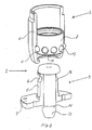
- Fig. 1 shows a perspective view of a coupling 1 that includes a first part 2 and a second part 3, where the first part 2 comprises a housing 4, and where the second part 3 comprises a projecting part 5 with a surrounding recess 6 and a connecting flange 7.
- Figs. 2 shows a cross-section of the coupling 1 in Fig. 1 , from which appears that
- the connecting flange 7 it is possible to secure the connecting flange 7 to an apparatus (not shown), whereby only the locking rod 13 is lowered/elevated. Only when the locking rod 13 is coupled to an apparatus (not shown) by means of recess 14, the apparatus is elevated (not shown), and the projecting part 5 is brought into connection with locking ring 8.
- Fig. 3 shows a cross-section of the coupling in Fig. 1 . From this appears that the second part 3 is inserted in locking ring 8 which is in a position where the locking balls 9 are pressed into a projecting position from lower side of wall 15 of the housing 4, so that the locking balls 9 interact with the surrounding recess (not shown) of the projecting part 5.
- Figs. 4-6 show the movement of a locking ring 8 in the housing 4,
- Figs. 4-6 it is furthermore possible to see the locking unit 17 which comprises an insert 18, a guide ring 19 and a rotor 20, where the guide ring 19 is connected to an upper edge of the housing 4, and the rotor 20 is actuated by a spring 21 which provide for the rotor 20 to pressed down towards locking ring 8.
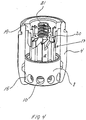
- Fig. 7 shows a locking unit 17 comprising an insert 18, a guide ring 19 and a rotor 20;
Landscapes
- Engineering & Computer Science (AREA)
- General Engineering & Computer Science (AREA)
- Mechanical Engineering (AREA)
- Quick-Acting Or Multi-Walled Pipe Joints (AREA)
- Mutual Connection Of Rods And Tubes (AREA)
- Mechanical Operated Clutches (AREA)
Applications Claiming Priority (2)
| Application Number | Priority Date | Filing Date | Title |
|---|---|---|---|
| DK200401444A DK176145B1 (da) | 2004-09-23 | 2004-09-23 | Kobling |
| PCT/DK2005/000592 WO2006032274A1 (en) | 2004-09-23 | 2005-09-21 | Coupling |
Publications (3)
| Publication Number | Publication Date |
|---|---|
| EP1815150A1 EP1815150A1 (en) | 2007-08-08 |
| EP1815150A4 EP1815150A4 (en) | 2012-11-28 |
| EP1815150B1 true EP1815150B1 (en) | 2018-05-16 |
Family
ID=36089861
Family Applications (1)
| Application Number | Title | Priority Date | Filing Date |
|---|---|---|---|
| EP05779737.5A Expired - Lifetime EP1815150B1 (en) | 2004-09-23 | 2005-09-21 | Coupling |
Country Status (5)
| Country | Link |
|---|---|
| US (1) | US7748091B2 (da) |
| EP (1) | EP1815150B1 (da) |
| AU (1) | AU2005287730B2 (da) |
| DK (2) | DK176145B1 (da) |
| WO (1) | WO2006032274A1 (da) |
Cited By (1)
| Publication number | Priority date | Publication date | Assignee | Title |
|---|---|---|---|---|
| CN111928041A (zh) * | 2020-07-31 | 2020-11-13 | 宁波奥克斯电气股份有限公司 | 一种排水管接头组件及空调器 |
Families Citing this family (24)
| Publication number | Priority date | Publication date | Assignee | Title |
|---|---|---|---|---|
| FR2910570B1 (fr) * | 2006-12-21 | 2012-04-27 | Karver | Dispositif pour la connexion/deconnexion de deux elements a partir d'un deplacement axial relatif de ces deux elements |
| US8353496B2 (en) * | 2007-12-07 | 2013-01-15 | William Steven Schwartz Revocable Trust | Trophy assembly with twist connector |
| JP4605285B2 (ja) * | 2008-11-25 | 2011-01-05 | 日本電気株式会社 | 基板組付体 |
| DK2332510T3 (da) * | 2009-12-09 | 2013-05-13 | Hoffmann La Roche | Forbindelsesorgan |
| EP2760270B1 (en) | 2011-09-29 | 2016-11-16 | Husqvarna AB | Quick-change blade system |
| RU2506466C1 (ru) * | 2012-06-22 | 2014-02-10 | Федеральное государственное бюджетное учреждение науки Институт неорганической химии им. А.В. Николаева Сибирского отделения Российской академии наук (ИНХ СО РАН) | Разъемное соединение |
| DE202012006290U1 (de) | 2012-06-29 | 2013-09-30 | Lukas Pregenzer | Inkontinenzimplantat |
| CN102864828B (zh) * | 2012-07-27 | 2014-12-31 | 厦门瑞尔特卫浴科技股份有限公司 | 进水阀快速拆装机构 |
| DE102013104389B4 (de) * | 2013-04-30 | 2014-12-18 | Bernd Stock | Verriegelungsvorrichtung und Verriegelungsanordnung |
| ITPD20130154A1 (it) * | 2013-05-31 | 2014-12-01 | Gitzo Sa | Supporto per apparecchiature fotografiche |
| US9534356B2 (en) * | 2013-05-31 | 2017-01-03 | Caterpillar Inc. | Retainer systems for ground engaging tools |
| US9631743B2 (en) | 2014-09-25 | 2017-04-25 | The Metraflex Company | Releasable connector for supporting a flexible conduit |
| US9447815B2 (en) | 2014-10-31 | 2016-09-20 | Magpul Industries Corp. | Quick detach accessory attachment |
| US9756930B2 (en) | 2015-04-28 | 2017-09-12 | Axon Enterprise, Inc. | Methods and apparatus for a low-profile coupler |
| CN105711815B (zh) * | 2016-04-20 | 2018-08-14 | 曾治蛟 | 一种螺旋桨快速拆装自锁机构 |
| KR20190095936A (ko) | 2016-12-14 | 2019-08-16 | 프로제너티, 인크. | 인테그린 저해제로의 위장관 질환의 치료 |
| CN107989875A (zh) * | 2017-11-30 | 2018-05-04 | 中电科技集团重庆声光电有限公司 | 一种快速连接与解脱结构 |
| WO2020106757A1 (en) | 2018-11-19 | 2020-05-28 | Progenity, Inc. | Ingestible device for delivery of therapeutic agent to the gastrointestinal tract |
| CN121197633A (zh) | 2019-12-13 | 2025-12-26 | 比特比德科有限责任公司 | 用于将治疗剂递送至胃肠道的可摄取装置 |
| US12055246B2 (en) | 2020-04-29 | 2024-08-06 | The Metraflex Company | Apparatus for supporting a flexible conduit having a releasable connector |
| US11326721B2 (en) | 2020-04-29 | 2022-05-10 | The Metraflex Company | Apparatus for supporting a flexible conduit having a releasable connector |
| TWM651341U (zh) * | 2023-11-22 | 2024-02-01 | 慶臨實業股份有限公司 | 接頭組件及具有該接頭組件的索環 |
| CN121174423A (zh) * | 2024-06-19 | 2025-12-19 | 南宁富联富桂精密工业有限公司 | 具防拆机构的电子装置及其操作方法 |
| CN223208936U (zh) * | 2024-09-29 | 2025-08-12 | 深圳市鸿泰电子五金有限公司 | 一种可调节绑绳长度的登山扣 |
Family Cites Families (27)
| Publication number | Priority date | Publication date | Assignee | Title |
|---|---|---|---|---|
| US2647798A (en) * | 1948-03-31 | 1953-08-04 | Edward D Ballard | Nozzle assembly for fire-fighting equipment |
| US2850298A (en) * | 1954-06-01 | 1958-09-02 | Snap Tite Inc | Quick detachable coupling |
| US2860893A (en) * | 1955-05-09 | 1958-11-18 | Snap Tite Inc | Ball detent type coupling with break-away feature |
| US3104088A (en) * | 1960-09-27 | 1963-09-17 | Crawford Fitting Co | Quick connect coupling |
| US3420497A (en) * | 1966-07-28 | 1969-01-07 | Srm Co | Misalignable fluid-tight coupling |
| US3430305A (en) * | 1967-05-19 | 1969-03-04 | Ted Geffner | Releasable connectors |
| US3667566A (en) * | 1970-05-28 | 1972-06-06 | William C N Hopkins | Releasable connector, particularly for tilt cab vehicles |
| FR2106694A5 (da) * | 1970-09-15 | 1972-05-05 | Staubli Sa Ets | |
| US4198080A (en) * | 1978-05-19 | 1980-04-15 | Baxter Travenol Laboratories, Inc. | Telescoping-type connector |
| US4366945A (en) | 1978-12-20 | 1983-01-04 | Abnox Ag | Hose coupling with double lock |
| FR2542243B1 (fr) * | 1983-03-11 | 1987-01-23 | Syspro | Porte-outil pour robot industriel |
| GB2175949B (en) * | 1985-05-29 | 1988-05-25 | Austen Barnes | Axial locking device |
| DE3723043A1 (de) * | 1987-07-11 | 1989-02-02 | Koehle Gmbh & Co Kg J | Steckverschluss fuer schmuckkette |
| GB8912650D0 (en) | 1989-06-02 | 1989-07-19 | Barnes Austen B | Axial locking device |
| GB9207258D0 (en) * | 1992-04-02 | 1992-05-13 | Barnes Austen Bernard | Axial locking device |
| US5410785A (en) * | 1993-09-29 | 1995-05-02 | Huang; Yu-Hwei | Device to detachably connect two objects |
| JPH07229592A (ja) | 1994-02-17 | 1995-08-29 | Hiroaki Taguchi | 迅速継手におけるキャップの錠止装置 |
| US5494323A (en) * | 1994-03-29 | 1996-02-27 | Huang; Yu-Hwei | Fasteners |
| JPH09264479A (ja) * | 1996-03-29 | 1997-10-07 | Toyota Motor Corp | クイックジョイント式カプラ |
| US6379072B1 (en) * | 1999-10-07 | 2002-04-30 | Burger Engineering, Inc. | Quick connect coupler with pneumatic release |
| US6619875B2 (en) * | 2001-06-25 | 2003-09-16 | Jung-Chang Chiang | Connection apparatus for an artificial model |
| US6568382B2 (en) * | 2001-09-28 | 2003-05-27 | Martin Archery, Inc. | Archery bows, connector apparatuses for archery bow accessories, and methods for removably securing archery bow accessories to archery bows |
| GB0209899D0 (en) | 2002-04-30 | 2002-06-05 | Guest John Int Ltd | Improvements in or relating to tube couplings |
| JP4286073B2 (ja) * | 2003-06-18 | 2009-06-24 | ニプロ株式会社 | 透析器接続用カプラ |
| DE10353903A1 (de) | 2003-11-18 | 2005-06-16 | Suspa Holding Gmbh | Längenverstellbare Druckfeder |
| US7258539B2 (en) * | 2004-08-16 | 2007-08-21 | Tooling Technology, Llc | Molding press with quick-change mold mounting system |
| US7963717B2 (en) * | 2007-10-25 | 2011-06-21 | Tooling Technology, Llc | Quick change locking coupler with condition sensor |
-
2004
- 2004-09-23 DK DK200401444A patent/DK176145B1/da not_active IP Right Cessation
-
2005
- 2005-09-21 AU AU2005287730A patent/AU2005287730B2/en not_active Ceased
- 2005-09-21 EP EP05779737.5A patent/EP1815150B1/en not_active Expired - Lifetime
- 2005-09-21 DK DK05779737.5T patent/DK1815150T3/da active
- 2005-09-21 WO PCT/DK2005/000592 patent/WO2006032274A1/en not_active Ceased
- 2005-09-21 US US11/663,792 patent/US7748091B2/en not_active Expired - Lifetime
Non-Patent Citations (1)
| Title |
|---|
| None * |
Cited By (2)
| Publication number | Priority date | Publication date | Assignee | Title |
|---|---|---|---|---|
| CN111928041A (zh) * | 2020-07-31 | 2020-11-13 | 宁波奥克斯电气股份有限公司 | 一种排水管接头组件及空调器 |
| CN111928041B (zh) * | 2020-07-31 | 2021-08-06 | 宁波奥克斯电气股份有限公司 | 一种排水管接头组件及空调器 |
Also Published As
| Publication number | Publication date |
|---|---|
| DK1815150T3 (da) | 2018-06-14 |
| DK176145B1 (da) | 2006-10-02 |
| AU2005287730B2 (en) | 2011-02-10 |
| US7748091B2 (en) | 2010-07-06 |
| AU2005287730A1 (en) | 2006-03-30 |
| EP1815150A4 (en) | 2012-11-28 |
| US20080073903A1 (en) | 2008-03-27 |
| WO2006032274A1 (en) | 2006-03-30 |
| EP1815150A1 (en) | 2007-08-08 |
| DK200401444A (da) | 2006-03-24 |
Similar Documents
| Publication | Publication Date | Title |
|---|---|---|
| US7748091B2 (en) | Coupling | |
| US6237964B1 (en) | Socket pipe coupling for subsea pipeline systems | |
| RU2381157C2 (ru) | Соединительная система для укладываемых в штабель емкостей | |
| AU713327B2 (en) | Pulley with pivoting flange and built-in jammer | |
| JPH03505111A (ja) | 自噴坑井の蓋装置 | |
| EP2722480A1 (en) | Connection appliance and connection arrangement comprising such a connection appliance | |
| US5904075A (en) | Interlocking jaw power tongs | |
| WO1998016351A1 (en) | Interlocking jaw power tongs | |
| JPS6038515B2 (ja) | 井戸用の滑動部ユニツト | |
| CA2239669C (en) | Movable backup bar assembly | |
| US8881801B2 (en) | Apparatus and method for the installation or removal of a rotary control device insert or a component thereof | |
| JPH0558582A (ja) | 吊り上げ用のグリツパー | |
| WO2015143329A1 (en) | Apparatus for the installation or removal of a rotary control device insert | |
| CN215558383U (zh) | 一种自动夹持装置 | |
| GB2416359A (en) | Elevators having a safety lock | |
| US5098253A (en) | Automatic tool-exchanging device | |
| CN117295873A (zh) | 一种管件拆装设备 | |
| CN113353791A (zh) | 一种自动夹持装置及操作方法 | |
| CN212803179U (zh) | 一种抽油机载荷卸载器及其锁扣装置 | |
| CA1230050A (fr) | Connecteur mobile relie a une conduite en boucle pour raccorder l'entree d'une tete de collecte avec la sortie d'une tete de puits | |
| CN210289595U (zh) | 轨道离合装置 | |
| US20250020252A1 (en) | Tubular coupling systems and methods | |
| JP3105739B2 (ja) | 原子炉燃料集合体の取扱工具 | |
| CN211034114U (zh) | 斜坡钢轨物料运输装置 | |
| CN209759016U (zh) | 垂管锁定装置以及装车鹤管 |
Legal Events
| Date | Code | Title | Description |
|---|---|---|---|
| PUAI | Public reference made under article 153(3) epc to a published international application that has entered the european phase |
Free format text: ORIGINAL CODE: 0009012 |
|
| 17P | Request for examination filed |
Effective date: 20070420 |
|
| AK | Designated contracting states |
Kind code of ref document: A1 Designated state(s): AT BE BG CH CY CZ DE DK EE ES FI FR GB GR HU IE IS IT LI LT LU LV MC NL PL PT RO SE SI SK TR |
|
| DAX | Request for extension of the european patent (deleted) | ||
| A4 | Supplementary search report drawn up and despatched |
Effective date: 20121030 |
|
| RIC1 | Information provided on ipc code assigned before grant |
Ipc: F16L 37/23 20060101ALI20121024BHEP Ipc: F16B 21/16 20060101AFI20121024BHEP Ipc: F16B 2/16 20060101ALI20121024BHEP |
|
| GRAP | Despatch of communication of intention to grant a patent |
Free format text: ORIGINAL CODE: EPIDOSNIGR1 |
|
| INTG | Intention to grant announced |
Effective date: 20171205 |
|
| RIN1 | Information on inventor provided before grant (corrected) |
Inventor name: BOEGH-SOERENSEN, OLE |
|
| GRAS | Grant fee paid |
Free format text: ORIGINAL CODE: EPIDOSNIGR3 |
|
| GRAA | (expected) grant |
Free format text: ORIGINAL CODE: 0009210 |
|
| AK | Designated contracting states |
Kind code of ref document: B1 Designated state(s): AT BE BG CH CY CZ DE DK EE ES FI FR GB GR HU IE IS IT LI LT LU LV MC NL PL PT RO SE SI SK TR |
|
| REG | Reference to a national code |
Ref country code: GB Ref legal event code: FG4D |
|
| REG | Reference to a national code |
Ref country code: CH Ref legal event code: EP |
|
| REG | Reference to a national code |
Ref country code: IE Ref legal event code: FG4D |
|
| REG | Reference to a national code |
Ref country code: DE Ref legal event code: R096 Ref document number: 602005053978 Country of ref document: DE Ref country code: DK Ref legal event code: T3 Effective date: 20180608 |
|
| REG | Reference to a national code |
Ref country code: AT Ref legal event code: REF Ref document number: 999863 Country of ref document: AT Kind code of ref document: T Effective date: 20180615 |
|
| REG | Reference to a national code |
Ref country code: NL Ref legal event code: FP |
|
| REG | Reference to a national code |
Ref country code: SE Ref legal event code: TRGR |
|
| REG | Reference to a national code |
Ref country code: FR Ref legal event code: PLFP Year of fee payment: 14 |
|
| REG | Reference to a national code |
Ref country code: LT Ref legal event code: MG4D |
|
| PG25 | Lapsed in a contracting state [announced via postgrant information from national office to epo] |
Ref country code: LT Free format text: LAPSE BECAUSE OF FAILURE TO SUBMIT A TRANSLATION OF THE DESCRIPTION OR TO PAY THE FEE WITHIN THE PRESCRIBED TIME-LIMIT Effective date: 20180516 Ref country code: FI Free format text: LAPSE BECAUSE OF FAILURE TO SUBMIT A TRANSLATION OF THE DESCRIPTION OR TO PAY THE FEE WITHIN THE PRESCRIBED TIME-LIMIT Effective date: 20180516 Ref country code: BG Free format text: LAPSE BECAUSE OF FAILURE TO SUBMIT A TRANSLATION OF THE DESCRIPTION OR TO PAY THE FEE WITHIN THE PRESCRIBED TIME-LIMIT Effective date: 20180816 Ref country code: ES Free format text: LAPSE BECAUSE OF FAILURE TO SUBMIT A TRANSLATION OF THE DESCRIPTION OR TO PAY THE FEE WITHIN THE PRESCRIBED TIME-LIMIT Effective date: 20180516 |
|
| PG25 | Lapsed in a contracting state [announced via postgrant information from national office to epo] |
Ref country code: GR Free format text: LAPSE BECAUSE OF FAILURE TO SUBMIT A TRANSLATION OF THE DESCRIPTION OR TO PAY THE FEE WITHIN THE PRESCRIBED TIME-LIMIT Effective date: 20180817 Ref country code: LV Free format text: LAPSE BECAUSE OF FAILURE TO SUBMIT A TRANSLATION OF THE DESCRIPTION OR TO PAY THE FEE WITHIN THE PRESCRIBED TIME-LIMIT Effective date: 20180516 |
|
| REG | Reference to a national code |
Ref country code: AT Ref legal event code: MK05 Ref document number: 999863 Country of ref document: AT Kind code of ref document: T Effective date: 20180516 |
|
| PG25 | Lapsed in a contracting state [announced via postgrant information from national office to epo] |
Ref country code: EE Free format text: LAPSE BECAUSE OF FAILURE TO SUBMIT A TRANSLATION OF THE DESCRIPTION OR TO PAY THE FEE WITHIN THE PRESCRIBED TIME-LIMIT Effective date: 20180516 Ref country code: AT Free format text: LAPSE BECAUSE OF FAILURE TO SUBMIT A TRANSLATION OF THE DESCRIPTION OR TO PAY THE FEE WITHIN THE PRESCRIBED TIME-LIMIT Effective date: 20180516 Ref country code: SK Free format text: LAPSE BECAUSE OF FAILURE TO SUBMIT A TRANSLATION OF THE DESCRIPTION OR TO PAY THE FEE WITHIN THE PRESCRIBED TIME-LIMIT Effective date: 20180516 Ref country code: RO Free format text: LAPSE BECAUSE OF FAILURE TO SUBMIT A TRANSLATION OF THE DESCRIPTION OR TO PAY THE FEE WITHIN THE PRESCRIBED TIME-LIMIT Effective date: 20180516 Ref country code: CZ Free format text: LAPSE BECAUSE OF FAILURE TO SUBMIT A TRANSLATION OF THE DESCRIPTION OR TO PAY THE FEE WITHIN THE PRESCRIBED TIME-LIMIT Effective date: 20180516 Ref country code: PL Free format text: LAPSE BECAUSE OF FAILURE TO SUBMIT A TRANSLATION OF THE DESCRIPTION OR TO PAY THE FEE WITHIN THE PRESCRIBED TIME-LIMIT Effective date: 20180516 |
|
| REG | Reference to a national code |
Ref country code: DE Ref legal event code: R097 Ref document number: 602005053978 Country of ref document: DE |
|
| PLBE | No opposition filed within time limit |
Free format text: ORIGINAL CODE: 0009261 |
|
| STAA | Information on the status of an ep patent application or granted ep patent |
Free format text: STATUS: NO OPPOSITION FILED WITHIN TIME LIMIT |
|
| 26N | No opposition filed |
Effective date: 20190219 |
|
| PG25 | Lapsed in a contracting state [announced via postgrant information from national office to epo] |
Ref country code: MC Free format text: LAPSE BECAUSE OF FAILURE TO SUBMIT A TRANSLATION OF THE DESCRIPTION OR TO PAY THE FEE WITHIN THE PRESCRIBED TIME-LIMIT Effective date: 20180516 |
|
| REG | Reference to a national code |
Ref country code: CH Ref legal event code: PL |
|
| PG25 | Lapsed in a contracting state [announced via postgrant information from national office to epo] |
Ref country code: SI Free format text: LAPSE BECAUSE OF FAILURE TO SUBMIT A TRANSLATION OF THE DESCRIPTION OR TO PAY THE FEE WITHIN THE PRESCRIBED TIME-LIMIT Effective date: 20180516 |
|
| REG | Reference to a national code |
Ref country code: BE Ref legal event code: MM Effective date: 20180930 |
|
| REG | Reference to a national code |
Ref country code: IE Ref legal event code: MM4A |
|
| PG25 | Lapsed in a contracting state [announced via postgrant information from national office to epo] |
Ref country code: LU Free format text: LAPSE BECAUSE OF NON-PAYMENT OF DUE FEES Effective date: 20180921 |
|
| PG25 | Lapsed in a contracting state [announced via postgrant information from national office to epo] |
Ref country code: IE Free format text: LAPSE BECAUSE OF NON-PAYMENT OF DUE FEES Effective date: 20180921 |
|
| PG25 | Lapsed in a contracting state [announced via postgrant information from national office to epo] |
Ref country code: CH Free format text: LAPSE BECAUSE OF NON-PAYMENT OF DUE FEES Effective date: 20180930 Ref country code: LI Free format text: LAPSE BECAUSE OF NON-PAYMENT OF DUE FEES Effective date: 20180930 Ref country code: BE Free format text: LAPSE BECAUSE OF NON-PAYMENT OF DUE FEES Effective date: 20180930 |
|
| PG25 | Lapsed in a contracting state [announced via postgrant information from national office to epo] |
Ref country code: TR Free format text: LAPSE BECAUSE OF FAILURE TO SUBMIT A TRANSLATION OF THE DESCRIPTION OR TO PAY THE FEE WITHIN THE PRESCRIBED TIME-LIMIT Effective date: 20180516 |
|
| PG25 | Lapsed in a contracting state [announced via postgrant information from national office to epo] |
Ref country code: PT Free format text: LAPSE BECAUSE OF FAILURE TO SUBMIT A TRANSLATION OF THE DESCRIPTION OR TO PAY THE FEE WITHIN THE PRESCRIBED TIME-LIMIT Effective date: 20180516 Ref country code: HU Free format text: LAPSE BECAUSE OF FAILURE TO SUBMIT A TRANSLATION OF THE DESCRIPTION OR TO PAY THE FEE WITHIN THE PRESCRIBED TIME-LIMIT; INVALID AB INITIO Effective date: 20050921 |
|
| PG25 | Lapsed in a contracting state [announced via postgrant information from national office to epo] |
Ref country code: CY Free format text: LAPSE BECAUSE OF FAILURE TO SUBMIT A TRANSLATION OF THE DESCRIPTION OR TO PAY THE FEE WITHIN THE PRESCRIBED TIME-LIMIT Effective date: 20180516 |
|
| PG25 | Lapsed in a contracting state [announced via postgrant information from national office to epo] |
Ref country code: IS Free format text: LAPSE BECAUSE OF FAILURE TO SUBMIT A TRANSLATION OF THE DESCRIPTION OR TO PAY THE FEE WITHIN THE PRESCRIBED TIME-LIMIT Effective date: 20180916 |
|
| PGFP | Annual fee paid to national office [announced via postgrant information from national office to epo] |
Ref country code: FR Payment date: 20200925 Year of fee payment: 16 Ref country code: GB Payment date: 20200928 Year of fee payment: 16 Ref country code: NL Payment date: 20200926 Year of fee payment: 16 Ref country code: DK Payment date: 20200929 Year of fee payment: 16 Ref country code: DE Payment date: 20200929 Year of fee payment: 16 |
|
| PGFP | Annual fee paid to national office [announced via postgrant information from national office to epo] |
Ref country code: IT Payment date: 20200923 Year of fee payment: 16 Ref country code: SE Payment date: 20200929 Year of fee payment: 16 |
|
| REG | Reference to a national code |
Ref country code: DE Ref legal event code: R119 Ref document number: 602005053978 Country of ref document: DE |
|
| REG | Reference to a national code |
Ref country code: DK Ref legal event code: EBP Effective date: 20210930 |
|
| REG | Reference to a national code |
Ref country code: SE Ref legal event code: EUG |
|
| REG | Reference to a national code |
Ref country code: NL Ref legal event code: MM Effective date: 20211001 |
|
| GBPC | Gb: european patent ceased through non-payment of renewal fee |
Effective date: 20210921 |
|
| PG25 | Lapsed in a contracting state [announced via postgrant information from national office to epo] |
Ref country code: NL Free format text: LAPSE BECAUSE OF NON-PAYMENT OF DUE FEES Effective date: 20211001 |
|
| PG25 | Lapsed in a contracting state [announced via postgrant information from national office to epo] |
Ref country code: SE Free format text: LAPSE BECAUSE OF NON-PAYMENT OF DUE FEES Effective date: 20210922 Ref country code: GB Free format text: LAPSE BECAUSE OF NON-PAYMENT OF DUE FEES Effective date: 20210921 Ref country code: FR Free format text: LAPSE BECAUSE OF NON-PAYMENT OF DUE FEES Effective date: 20210930 Ref country code: DE Free format text: LAPSE BECAUSE OF NON-PAYMENT OF DUE FEES Effective date: 20220401 |
|
| PG25 | Lapsed in a contracting state [announced via postgrant information from national office to epo] |
Ref country code: IT Free format text: LAPSE BECAUSE OF NON-PAYMENT OF DUE FEES Effective date: 20210921 Ref country code: DK Free format text: LAPSE BECAUSE OF NON-PAYMENT OF DUE FEES Effective date: 20210930 |