EP1815183B1 - Leuchte und lamellenraster dafür - Google Patents
Leuchte und lamellenraster dafür Download PDFInfo
- Publication number
- EP1815183B1 EP1815183B1 EP05801234A EP05801234A EP1815183B1 EP 1815183 B1 EP1815183 B1 EP 1815183B1 EP 05801234 A EP05801234 A EP 05801234A EP 05801234 A EP05801234 A EP 05801234A EP 1815183 B1 EP1815183 B1 EP 1815183B1
- Authority
- EP
- European Patent Office
- Prior art keywords
- lamellae
- luminaire
- outer edge
- light emission
- inner face
- Prior art date
- Legal status (The legal status is an assumption and is not a legal conclusion. Google has not performed a legal analysis and makes no representation as to the accuracy of the status listed.)
- Expired - Lifetime
Links
Images

Classifications
-
- F—MECHANICAL ENGINEERING; LIGHTING; HEATING; WEAPONS; BLASTING
- F21—LIGHTING
- F21V—FUNCTIONAL FEATURES OR DETAILS OF LIGHTING DEVICES OR SYSTEMS THEREOF; STRUCTURAL COMBINATIONS OF LIGHTING DEVICES WITH OTHER ARTICLES, NOT OTHERWISE PROVIDED FOR
- F21V11/00—Screens not covered by groups F21V1/00, F21V3/00, F21V7/00 or F21V9/00
- F21V11/02—Screens not covered by groups F21V1/00, F21V3/00, F21V7/00 or F21V9/00 using parallel laminae or strips, e.g. of Venetian-blind type
-
- F—MECHANICAL ENGINEERING; LIGHTING; HEATING; WEAPONS; BLASTING
- F21—LIGHTING
- F21S—NON-PORTABLE LIGHTING DEVICES; SYSTEMS THEREOF; VEHICLE LIGHTING DEVICES SPECIALLY ADAPTED FOR VEHICLE EXTERIORS
- F21S8/00—Lighting devices intended for fixed installation
- F21S8/02—Lighting devices intended for fixed installation of recess-mounted type, e.g. downlighters
- F21S8/026—Lighting devices intended for fixed installation of recess-mounted type, e.g. downlighters intended to be recessed in a ceiling or like overhead structure, e.g. suspended ceiling
-
- F—MECHANICAL ENGINEERING; LIGHTING; HEATING; WEAPONS; BLASTING
- F21—LIGHTING
- F21V—FUNCTIONAL FEATURES OR DETAILS OF LIGHTING DEVICES OR SYSTEMS THEREOF; STRUCTURAL COMBINATIONS OF LIGHTING DEVICES WITH OTHER ARTICLES, NOT OTHERWISE PROVIDED FOR
- F21V13/00—Producing particular characteristics or distribution of the light emitted by means of a combination of elements specified in two or more of main groups F21V1/00 - F21V11/00
- F21V13/02—Combinations of only two kinds of elements
- F21V13/10—Combinations of only two kinds of elements the elements being reflectors and screens
-
- F—MECHANICAL ENGINEERING; LIGHTING; HEATING; WEAPONS; BLASTING
- F21—LIGHTING
- F21Y—INDEXING SCHEME ASSOCIATED WITH SUBCLASSES F21K, F21L, F21S and F21V, RELATING TO THE FORM OR THE KIND OF THE LIGHT SOURCES OR OF THE COLOUR OF THE LIGHT EMITTED
- F21Y2103/00—Elongate light sources, e.g. fluorescent tubes
Definitions
- the invention relates to a luminaire provided with:
- the invention also relates to a lamellae louver comprising a plurality of substantially parallel, substantially equidistant, interconnected lamellae having a V-shaped cross-section, an outer edge, and an inner face facing away therefrom, the outer edge having a central portion in which the outer edge has a concave shape and straight end portions.
- the lamellae of said prior luminaire and louver have intermediate portions between the central portion and the end portions. They have a very small height h 0 in their center related to the width W and are mounted close to the accommodated lamp, remote from the light emission window.
- the side reflectors collect the light generated by an operating accommodated electric lamp Ls into a beam and create a shielding angle aside the luminaire within which the lamp is not visible.
- the lamellae have a shielding function in plane P and in planes surrounding plane P to avoid that the lamp can be seen from within an angle corresponding to said shielding angle.
- the lamellae have a triangular cross-section, the base of which is inside the luminaire.
- the flanks of the lamellae may be flat or concave.
- Such lamellae are required if the luminaire is intended for use in rooms in which computer terminals are present.
- Light rays reflected by the lamellae are reflected at a greater angle to the light emission window, owing to the triangular cross-section, than corresponding light rays by flat lamellae. It is avoided thereby that light rays are reflected within the shielding angle in plane P and in surrounding planes and cause annoying reflections on screens of terminals.
- lamellae It is another function of the lamellae to prevent that images of the lamp formed in the side reflectors can be observed within the shielding angle.
- lamellae In order to achieve this, lamellae generally are relatively extended and voluminous, having the effect that additional reflections occur in the luminaire which cause loss of light due to absorption at each reflection.
- the shielding angle ⁇ of e.g. 30 is the angle from the edge of a side reflector downwards.
- a proper luminaire creates such a shielding not only in a vertical plane C 0 , transverse to the edge, but also in all adjacent planes up to about plane C 45 by means of the side reflector, and up to plane C 90 , which coincides with plane P, by means of the lamellae.
- the first object is achieved in that the luminaire has the features of claim 1.
- the luminaire To counteract glare and to satisfy the said URG 19 requirement, the luminaire must have each of the features of claim 1.
- the invention is based on the recognition that at an angle in the range of ⁇ to approximately ⁇ + 10° strong intensity variations occur in the region of approximately plane C 45 to approximately plane C 60 owing to the sudden increase in size of lampdetails and of lamp images in the side reflector, and that these intensity variations cause glare.
- the end portions have a length smaller than 0.15, a correction of intensity variations is brought about that is insufficient for complying with the aforementioned standard. If said length is greater than 0.25, the shielding in planes in the range of approximately C 60 to approximately C 80 is too strong.
- Said correction is achieved only when the lamellae are present in the light emission window.
- the outer edges of the end portions are in line with one another, enclose an angle of 180°, or each have a deviation therefrom of up to 5° outwards, enclose an angle of up to 170°, or inwards, enclose an angle of up to 190°, otherwise the correction required is impeded.
- the central portion has the size which follows from W and the length of the end portion, otherwise too strong a shielding in and immediately around plane C 90 is obtained.
- the luminaire of the invention admits of the use of a relatively small number of lamellae of relatively great height, great h 0 , extending up to a small distance of a few mm away from the lamp to be accommodated, and of the use of a relatively large number of lamellae of small h 0 for achieving a same shielding in longitudinal directions.
- the material content of the lamellae is small compared with the content of the lamellae of the luminaire of the cited EPB-0 757 772, which have a fully concave outer edge.
- This advantage is particularly considerable when the lamellae are of high-quality mirroring material, which is rather expensive.
- the advantage also plays a role if the lamellae are of synthetic resin such as polycarbonate (PC), polystyrene (PS), or polystyrene.acrylonitril-butadienenstyrene (PS.ABS), because expensive heat-resistant resins must be used for safety reasons.
- PC polycarbonate
- PS polystyrene
- PS.ABS polystyrene.acrylonitril-butadienenstyrene
- the inner face may be blackened, which causes loss of light, however, or be profiled to direct reflected light deeper into the luminaire than would otherwise occur.
- the inner face may be open adjacent the side reflectors. The area from which annoying light rays could leave is absent then, whereas the remaining inner face can reflect light to limit the loss of light.
- the inner face has a concave curvature transverse to plane P for the said purpose. Light is reflected by the inner face deeper into the luminaire also in this case, and subsequent reflections into the shielding angle ⁇ are effectively counteracted. Loss of light is minimized thereby.
- the lamellae have a relatively small greatest height, i.e. the dimension transverse to the light emission window, compared with the lamellae of the cited EPB-0 757 772, owing to the straight end portions. This renders it possible for the luminaire to have the features of claim 4 and nevertheless produce an excellent light beam.
- a kink in the flanks parallel to the light emission window is not required to prevent the inner face from being rather broad at its ends.
- a narrow inner face is of interest, because the narrower the inner face, the fewer reflections will occur and the less loss of light will be caused by absorption.
- the width of the inner face is determined by its width in plane P.
- the lamellae may have the features of claim 6.
- the advantage thereof is that the inner face of the lamella is at least substantially optically closed.
- the outer edge is thinnest if the flanks meet there in an abutting manner only. A fold in the region of the end portions to connect both flanks is thicker than two abutting flanks.
- the thickness at the outer edge determines the width of the inner face in plane P.
- a small thickness at the outer edge and a small width of the inner face are of importance, because any obstruction to the passage of light is small then.
- the lamellae may be made of metal, e.g. aluminum, and be specularly or semi-specularly reflecting.
- the lamellae may be inseparably connected to the side reflectors.
- the luminaire has the feature of claim 7.
- a louver of plastic is easy to manufacture and has the advantage that much assembling work is avoided that would be necessary if the lamellae were separate bodies.
- the louver may e.g. have a click connection to the side reflectors.
- the louver may be connected to end faces of the luminaire.
- the second object of the invention is achieved by a lamellae louver having the features of claim 8.
- the side reflectors may be united to form a reflector body which is also present opposite the light emission window.
- the luminaire may also or alternatively be present in a housing.
- An e.g. lacquer-coated wall thereof opposite the light emission window may constitute a reflector.
- the luminaire may, however, have a second window opposite the light emission window in order also to provide indirect lighting.
- the luminaire may be used for illuminating e.g. offices and shops.
- a housing of the luminaire may contain two or more of the luminaire units described.
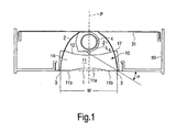
- the luminaire has a light emission window 1 of a width W.
- Elongate side reflectors 2 are placed opposite each other, equidistant from a plane P that is perpendicular to the light emission window 1, which side reflectors 2 each have an edge 3 defining the width W of the light emission window 2. They are concavely curved transverse to the edge 3, inclining towards one another in a direction away from the light emission window 1.
- Means 4 are present for accommodating an elongate electric lamp Ls between the side reflectors 2, along the light emission window 1, and in plane P.
- the means 4 are a pair of lampholders, one of which is visible, for accommodating a low-pressure mercury fluorescent lamp.
- a plurality of substantially parallel, substantially equidistant lamellae 10 are present, transverse to plane P and to the light emission window 1.
- the lamellae 10 each have a V-shaped cross-section, an outer edge 11 which is remote from the means 4, and an inner face 12 remote from the light emission window 1.
- the outer edge 11 has a central portion 11a through plane P in which the outer edge 11 has a concave shape, and straight end portions 11b adjacent the side reflectors 2.
- the lamellae 10 have a length W and are present in the light emission window 1.
- the central portion 11a of the outer edge 11 directly merges into the straight end portions 11b.
- the straight end portions 11b each have a length in the range of 0.15 to 0.25 W and are at an angle in the range of 170° to 190° to one another. In the Fig. the straight end portions 11b each have a length of 0.18 W. They are at an angle of 180°.
- W is in the range of 40 to 64 mm. In the Fig. W is 55 mm.
- Fig. 1 shows the luminaire in a housing 30, the top wall 31 of which is coated white to act as a reflector.
- the inner face 12 of the lamellae 10 has a concave curvature transverse to plane P to reflect light rays deeper into the luminaire than would otherwise occur. It is achieved thereby that the side reflectors reflect these rays more steeply and outside the shielding angle ⁇ .
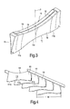
- the luminaire of Fig. 1 has lamellae 10, each of which has flanks 15 which extend from the outer edge 11 up to the inner face 12 and are concavely curved, the curvature diminishing from relatively strong in plane P to relatively weak adjacent the side reflectors 2. This is best seen in Fig. 2 .
- the lines drawn in the flanks 15 show the curvature of the flanks 15.
- the lamellae 10 are each made from a respective piece 40 of sheet metal, as shown in Fig. 3 , and have folding lines 13 bounding the inner face 12 and the flanks 15, which lines extend between the inner face 12 and the outer edge 11.
- the flanks 15 only abut one another at the outer edge 11, as is apparent from Fig. 2 .
- the lamella 10 of Fig. 2 is one unitary member because of the presence of bridges 16, see Fig. 3 , which in Fig. 1 are outside the side reflectors 2, because the side reflectors 2 snap into holes 17 and recesses 18.
- the shaped piece shown in Fig. 2 results in the lamella 10 of Fig. 3 , having a longitudinal gap in the inner face 12.
- the inner face 12 of Fig. 3 is constituted by overlapping portions 14.
- Fig. 2 also shows in dashed lines an alternative in which the end portions 11b' enclose an angle of 170° .with one another.
- the luminaire complies with the requirements of the cited standard also if a very bright lamp is operated therein.
- the luminaire causes an additional shielding of a few degrees in the region of planes C 45 to C 60 , but it was found that this causes substantially no loss of light.
- the present lamellae 10 have a smaller surface area and thus cause fewer reflections.
- the lamellae 10 may be united to constitute a louver which is detachably connected to the side reflectors 2. This is particularly useful in the case of plastic lamellae 10.
- the lamella louver of Fig. 4 has a plurality of substantially parallel, substantially equidistant, interconnected lamellae 10, which each have a V-shaped cross-section, an outer edge 11, and an inner face 12.
- the outer edge 11 has a central portion 11a in which the outer edge 11 has a concave shape and straight end portions 11b.
- the lamellae 10 have a length W, the central portion 11a of the outer edge 11 merging directly into the straight end portions 11b, which each have a length in the range of 0.15 to 0.25 W, and enclose an angle in the range of 170° to 190° with one another.
Landscapes
- Engineering & Computer Science (AREA)
- General Engineering & Computer Science (AREA)
- Securing Globes, Refractors, Reflectors Or The Like (AREA)
- Non-Portable Lighting Devices Or Systems Thereof (AREA)
- Transition And Organic Metals Composition Catalysts For Addition Polymerization (AREA)
- Optical Elements Other Than Lenses (AREA)
Claims (8)
- Leuchte, versehen mit:einem Lichtemissionsfenster (1) mit einer Breite W;länglichen Seitenreflektoren (2), die in gleichem Abstand von einer Ebene P, die senkrecht zu dem Lichtemissionsfenster (1) verläuft, einander gegenüberliegend angeordnet sind, wobei die Seitenreflektoren (2) jeweils einen die Breite W des Lichtemissionsfenster (2) definierenden Rand (3) aufweisen und quer zu dem Rand (3) konkav gekrümmt sind, wobei diese in einer Richtung von dem Lichtemissionsfenster (1) weg zueinander geneigt sind;Mitteln (4), um zwischen den Seitenreflektoren (2), entlang dem Lichtemissionsfenster (1) und in Ebene P, eine längliche, elektrische Lampe Ls aufzunehmen; sowiemehreren, im Wesentlichen parallelen, im Wesentlichen gleich weit entfernten Lamellen (10) quer zur Ebene P und zu dem Lichtemissionsfenster (1),wobei die Lamellen (10) jeweils einen V-förmigen Querschnitt, einen äußeren Rand (11), der von den Mitteln (4) entfernt vorgesehen ist, sowie eine von dem Lichtemissionsfenster (1) entfernte Innenseite (12) aufweisen, wobei der äußere Rand (11) einen mittleren Abschnitt (11a) durch Ebene P aufweist, in dem der äußere Rand (11) eine konkave Form und gerade Endabschnitte (11b) in Angrenzung an die Seitenreflektoren (2) hat, wobeidie Lamellen (10) eine Länge W aufweisen und in dem Lichtemissionsfenster (1) vorhanden sind,der mittlere Abschnitt (11a) des äußeren Randes (11) unmittelbar in die geraden Endabschnitte (11b) übergeht, dadurch gekennzeichnet, dassdie geraden Endabschnitte (11b) jeweils eine Länge im Bereich von 0,15 bis 0,25 W aufweisenund einen Winkel im Bereich von 170° bis 190° zueinander einschließen.
- Leuchte nach Anspruch 1, dadurch gekennzeichnet, dass W im Bereich von 40 bis 64 mm liegt.
- Leuchte nach Anspruch 1 oder 2, dadurch gekennzeichnet, dass die Innenseite (12) eine konkave Krümmung quer zur Ebene P aufweist.
- Leuchte nach Anspruch 3, dadurch gekennzeichnet, dass jede Lamelle (10) Flanken (15) aufweist, die sich von dem äußeren Rand (11) bis zu der Innenseite (12) erstrecken und konkav gekrümmt sind, wobei sich die Krümmung von relativ stark in Ebene P bis relativ schwach in Angrenzung an die Seitenreflektoren (2) verringert.
- Leuchte nach Anspruch 4, dadurch gekennzeichnet, dass die Innenseite (12) über ihre Länge eine im Wesentlichen konstante Breite aufweist.
- Leuchte nach Anspruch 1 oder 2, dadurch gekennzeichnet, dass die Lamellen (10) jeweils aus einem jeweiligen Stück (40) Blech gefertigt sind und Faltlinien (13) aufweisen, welche die Innenseite (12) und Flanken (15) begrenzen, die sich zwischen der Innenseite (12) und dem äußeren Rand (11) erstrecken und an dem äußeren Rand (11) lediglich aneinander anliegen, wobei die Innenseite (12) durch sich überlappende Abschnitte (14) gebildet wird.
- Leuchte nach Anspruch 1 oder 2, dadurch gekennzeichnet, dass die Lamellen (10) so verbunden sind, dass sie ein Raster (20) bilden, das mit den Seitenreflektoren (2) abnehmbar verbunden ist.
- Lamellenraster (20), das zur Verwendung in der Leuchte nach Anspruch 1 konzipiert wurde, mit mehreren, im Wesentlichen parallelen, im Wesentlichen gleich weit entfernten, miteinander verbundenen Lamellen (10), die jeweils einen V-förmigen Querschnitt, einen äußeren Rand (11) sowie eine von diesem abgewandte Innenseite (12) aufweisen,
wobei der äußere Rand (11) einen mittleren Abschnitt (11a) aufweist, in dem der äußere Rand (11) eine konkave Form und gerade Endabschnitte (11b) aufweist,
wobei die Lamellen (10) eine Länge W haben,
wobei der mittlere Abschnitt (11a) des äußeren Randes (11) unmittelbar in die geraden Endabschnitte (11b) übergeht, dadurch gekennzeichnet, dass
die geraden Endabschnitte (11b) jeweils eine Länge im Bereich von 0,15 bis 0,25 W aufweisen
und einen Winkel im Bereich von 170° bis 190° zueinander einschließen.
Priority Applications (1)
| Application Number | Priority Date | Filing Date | Title |
|---|---|---|---|
| EP05801234A EP1815183B1 (de) | 2004-11-12 | 2005-11-07 | Leuchte und lamellenraster dafür |
Applications Claiming Priority (3)
| Application Number | Priority Date | Filing Date | Title |
|---|---|---|---|
| EP04105738 | 2004-11-12 | ||
| PCT/IB2005/053648 WO2006051473A1 (en) | 2004-11-12 | 2005-11-07 | Luminaire and lamellae louver therefor |
| EP05801234A EP1815183B1 (de) | 2004-11-12 | 2005-11-07 | Leuchte und lamellenraster dafür |
Publications (2)
| Publication Number | Publication Date |
|---|---|
| EP1815183A1 EP1815183A1 (de) | 2007-08-08 |
| EP1815183B1 true EP1815183B1 (de) | 2011-05-04 |
Family
ID=35985845
Family Applications (1)
| Application Number | Title | Priority Date | Filing Date |
|---|---|---|---|
| EP05801234A Expired - Lifetime EP1815183B1 (de) | 2004-11-12 | 2005-11-07 | Leuchte und lamellenraster dafür |
Country Status (7)
| Country | Link |
|---|---|
| US (1) | US8118453B2 (de) |
| EP (1) | EP1815183B1 (de) |
| JP (1) | JP4949261B2 (de) |
| CN (1) | CN101057102A (de) |
| AT (1) | ATE508325T1 (de) |
| DE (1) | DE602005027886D1 (de) |
| WO (1) | WO2006051473A1 (de) |
Families Citing this family (3)
| Publication number | Priority date | Publication date | Assignee | Title |
|---|---|---|---|---|
| US8576406B1 (en) | 2009-02-25 | 2013-11-05 | Physical Optics Corporation | Luminaire illumination system and method |
| CN201407599Y (zh) * | 2009-04-24 | 2010-02-17 | 富昱电机股份有限公司 | 灯管灯具 |
| US11982424B1 (en) * | 2023-08-18 | 2024-05-14 | Elemental LED, Inc. | External louvers for linear luminaire |
Family Cites Families (9)
| Publication number | Priority date | Publication date | Assignee | Title |
|---|---|---|---|---|
| AU700856B2 (en) * | 1995-02-14 | 1999-01-14 | Koninklijke Philips Electronics N.V. | Luminaire |
| US5528478A (en) * | 1995-10-04 | 1996-06-18 | Cooper Industries, Inc. | Lighting fixture having a parabolic louver |
| DE29801988U1 (de) * | 1998-02-06 | 1998-05-20 | Wagner, Hans, Dipl.-Ing., 79761 Waldshut-Tiengen | Vorrichtung zur Verbesserung des Wirkungsgrades bei Leuchten mit Lamellenraster |
| ES2272038T3 (es) * | 1998-05-19 | 2007-04-16 | Koninklijke Philips Electronics N.V. | Luminaria. |
| GB9908728D0 (en) * | 1999-04-17 | 1999-06-09 | Luxonic Lightng Plc | A lighting appliance |
| ATE382827T1 (de) * | 1999-12-27 | 2008-01-15 | Ludwig Leuchten Kg | Leuchte |
| US6626560B1 (en) * | 2000-11-22 | 2003-09-30 | Ronald N. Caferro | Lighting louver |
| CN1625667B (zh) * | 2002-01-28 | 2012-12-05 | 皇家飞利浦电子股份有限公司 | 用于管状灯的带有薄片的照明装置 |
| DE60315468T2 (de) * | 2002-08-01 | 2008-04-17 | Koninklijke Philips Electronics N.V. | Leuchte und lamellenraster dafür |
-
2005
- 2005-11-07 US US11/718,725 patent/US8118453B2/en not_active Expired - Fee Related
- 2005-11-07 WO PCT/IB2005/053648 patent/WO2006051473A1/en not_active Ceased
- 2005-11-07 CN CNA200580038748XA patent/CN101057102A/zh active Pending
- 2005-11-07 EP EP05801234A patent/EP1815183B1/de not_active Expired - Lifetime
- 2005-11-07 JP JP2007540779A patent/JP4949261B2/ja not_active Expired - Fee Related
- 2005-11-07 DE DE602005027886T patent/DE602005027886D1/de not_active Expired - Lifetime
- 2005-11-07 AT AT05801234T patent/ATE508325T1/de not_active IP Right Cessation
Also Published As
| Publication number | Publication date |
|---|---|
| WO2006051473A1 (en) | 2006-05-18 |
| US8118453B2 (en) | 2012-02-21 |
| DE602005027886D1 (de) | 2011-06-16 |
| EP1815183A1 (de) | 2007-08-08 |
| JP4949261B2 (ja) | 2012-06-06 |
| JP2008520073A (ja) | 2008-06-12 |
| CN101057102A (zh) | 2007-10-17 |
| US20080130287A1 (en) | 2008-06-05 |
| ATE508325T1 (de) | 2011-05-15 |
Similar Documents
| Publication | Publication Date | Title |
|---|---|---|
| US7481552B2 (en) | Light fixture having a reflector assembly and a lens assembly for same | |
| US7455422B2 (en) | Light fixture and lens assembly for same | |
| US7510305B2 (en) | Air-handling light fixture and lens assembly for same | |
| US6443598B1 (en) | Lighting appliance with glare reducing cross blades | |
| US5758954A (en) | Luminaire | |
| CN1582377A (zh) | 照明器及其薄板格栅 | |
| EP1606552B1 (de) | Leuchte | |
| CA2175554C (en) | Indirect asymmetric luminaire assembly | |
| EP1815183B1 (de) | Leuchte und lamellenraster dafür | |
| US7905636B2 (en) | Luminaire and lamellae louver | |
| EP1472491B1 (de) | Leuchte mit leuchtenraster, für rohrförmige lampe | |
| CN100472122C (zh) | 照明装置及其薄片叶片 | |
| US20070223229A1 (en) | Luminaire and Lamellae Louver Therefor | |
| JP2007294315A (ja) | 反射体および照明器具 |
Legal Events
| Date | Code | Title | Description |
|---|---|---|---|
| PUAI | Public reference made under article 153(3) epc to a published international application that has entered the european phase |
Free format text: ORIGINAL CODE: 0009012 |
|
| 17P | Request for examination filed |
Effective date: 20070612 |
|
| AK | Designated contracting states |
Kind code of ref document: A1 Designated state(s): AT BE BG CH CY CZ DE DK EE ES FI FR GB GR HU IE IS IT LI LT LU LV MC NL PL PT RO SE SI SK TR |
|
| 17Q | First examination report despatched |
Effective date: 20071031 |
|
| DAX | Request for extension of the european patent (deleted) | ||
| RAP1 | Party data changed (applicant data changed or rights of an application transferred) |
Owner name: KONINKLIJKE PHILIPS ELECTRONICS N.V. |
|
| GRAP | Despatch of communication of intention to grant a patent |
Free format text: ORIGINAL CODE: EPIDOSNIGR1 |
|
| GRAS | Grant fee paid |
Free format text: ORIGINAL CODE: EPIDOSNIGR3 |
|
| GRAA | (expected) grant |
Free format text: ORIGINAL CODE: 0009210 |
|
| AK | Designated contracting states |
Kind code of ref document: B1 Designated state(s): AT BE BG CH CY CZ DE DK EE ES FI FR GB GR HU IE IS IT LI LT LU LV MC NL PL PT RO SE SI SK TR |
|
| REG | Reference to a national code |
Ref country code: GB Ref legal event code: FG4D |
|
| REG | Reference to a national code |
Ref country code: CH Ref legal event code: EP |
|
| REG | Reference to a national code |
Ref country code: IE Ref legal event code: FG4D |
|
| REF | Corresponds to: |
Ref document number: 602005027886 Country of ref document: DE Date of ref document: 20110616 Kind code of ref document: P |
|
| REG | Reference to a national code |
Ref country code: DE Ref legal event code: R096 Ref document number: 602005027886 Country of ref document: DE Effective date: 20110616 |
|
| REG | Reference to a national code |
Ref country code: NL Ref legal event code: VDEP Effective date: 20110504 |
|
| PG25 | Lapsed in a contracting state [announced via postgrant information from national office to epo] |
Ref country code: PT Free format text: LAPSE BECAUSE OF FAILURE TO SUBMIT A TRANSLATION OF THE DESCRIPTION OR TO PAY THE FEE WITHIN THE PRESCRIBED TIME-LIMIT Effective date: 20110905 Ref country code: LT Free format text: LAPSE BECAUSE OF FAILURE TO SUBMIT A TRANSLATION OF THE DESCRIPTION OR TO PAY THE FEE WITHIN THE PRESCRIBED TIME-LIMIT Effective date: 20110504 Ref country code: SE Free format text: LAPSE BECAUSE OF FAILURE TO SUBMIT A TRANSLATION OF THE DESCRIPTION OR TO PAY THE FEE WITHIN THE PRESCRIBED TIME-LIMIT Effective date: 20110504 |
|
| PG25 | Lapsed in a contracting state [announced via postgrant information from national office to epo] |
Ref country code: GR Free format text: LAPSE BECAUSE OF FAILURE TO SUBMIT A TRANSLATION OF THE DESCRIPTION OR TO PAY THE FEE WITHIN THE PRESCRIBED TIME-LIMIT Effective date: 20110805 Ref country code: LV Free format text: LAPSE BECAUSE OF FAILURE TO SUBMIT A TRANSLATION OF THE DESCRIPTION OR TO PAY THE FEE WITHIN THE PRESCRIBED TIME-LIMIT Effective date: 20110504 Ref country code: FI Free format text: LAPSE BECAUSE OF FAILURE TO SUBMIT A TRANSLATION OF THE DESCRIPTION OR TO PAY THE FEE WITHIN THE PRESCRIBED TIME-LIMIT Effective date: 20110504 Ref country code: IS Free format text: LAPSE BECAUSE OF FAILURE TO SUBMIT A TRANSLATION OF THE DESCRIPTION OR TO PAY THE FEE WITHIN THE PRESCRIBED TIME-LIMIT Effective date: 20110904 Ref country code: ES Free format text: LAPSE BECAUSE OF FAILURE TO SUBMIT A TRANSLATION OF THE DESCRIPTION OR TO PAY THE FEE WITHIN THE PRESCRIBED TIME-LIMIT Effective date: 20110815 Ref country code: SI Free format text: LAPSE BECAUSE OF FAILURE TO SUBMIT A TRANSLATION OF THE DESCRIPTION OR TO PAY THE FEE WITHIN THE PRESCRIBED TIME-LIMIT Effective date: 20110504 Ref country code: AT Free format text: LAPSE BECAUSE OF FAILURE TO SUBMIT A TRANSLATION OF THE DESCRIPTION OR TO PAY THE FEE WITHIN THE PRESCRIBED TIME-LIMIT Effective date: 20110504 Ref country code: BE Free format text: LAPSE BECAUSE OF FAILURE TO SUBMIT A TRANSLATION OF THE DESCRIPTION OR TO PAY THE FEE WITHIN THE PRESCRIBED TIME-LIMIT Effective date: 20110504 Ref country code: CY Free format text: LAPSE BECAUSE OF FAILURE TO SUBMIT A TRANSLATION OF THE DESCRIPTION OR TO PAY THE FEE WITHIN THE PRESCRIBED TIME-LIMIT Effective date: 20110504 |
|
| PG25 | Lapsed in a contracting state [announced via postgrant information from national office to epo] |
Ref country code: NL Free format text: LAPSE BECAUSE OF FAILURE TO SUBMIT A TRANSLATION OF THE DESCRIPTION OR TO PAY THE FEE WITHIN THE PRESCRIBED TIME-LIMIT Effective date: 20110504 |
|
| PG25 | Lapsed in a contracting state [announced via postgrant information from national office to epo] |
Ref country code: CZ Free format text: LAPSE BECAUSE OF FAILURE TO SUBMIT A TRANSLATION OF THE DESCRIPTION OR TO PAY THE FEE WITHIN THE PRESCRIBED TIME-LIMIT Effective date: 20110504 Ref country code: EE Free format text: LAPSE BECAUSE OF FAILURE TO SUBMIT A TRANSLATION OF THE DESCRIPTION OR TO PAY THE FEE WITHIN THE PRESCRIBED TIME-LIMIT Effective date: 20110504 |
|
| PG25 | Lapsed in a contracting state [announced via postgrant information from national office to epo] |
Ref country code: RO Free format text: LAPSE BECAUSE OF FAILURE TO SUBMIT A TRANSLATION OF THE DESCRIPTION OR TO PAY THE FEE WITHIN THE PRESCRIBED TIME-LIMIT Effective date: 20110504 Ref country code: DK Free format text: LAPSE BECAUSE OF FAILURE TO SUBMIT A TRANSLATION OF THE DESCRIPTION OR TO PAY THE FEE WITHIN THE PRESCRIBED TIME-LIMIT Effective date: 20110504 Ref country code: SK Free format text: LAPSE BECAUSE OF FAILURE TO SUBMIT A TRANSLATION OF THE DESCRIPTION OR TO PAY THE FEE WITHIN THE PRESCRIBED TIME-LIMIT Effective date: 20110504 Ref country code: PL Free format text: LAPSE BECAUSE OF FAILURE TO SUBMIT A TRANSLATION OF THE DESCRIPTION OR TO PAY THE FEE WITHIN THE PRESCRIBED TIME-LIMIT Effective date: 20110504 |
|
| PLBE | No opposition filed within time limit |
Free format text: ORIGINAL CODE: 0009261 |
|
| STAA | Information on the status of an ep patent application or granted ep patent |
Free format text: STATUS: NO OPPOSITION FILED WITHIN TIME LIMIT |
|
| 26N | No opposition filed |
Effective date: 20120207 |
|
| PG25 | Lapsed in a contracting state [announced via postgrant information from national office to epo] |
Ref country code: IT Free format text: LAPSE BECAUSE OF FAILURE TO SUBMIT A TRANSLATION OF THE DESCRIPTION OR TO PAY THE FEE WITHIN THE PRESCRIBED TIME-LIMIT Effective date: 20110504 |
|
| REG | Reference to a national code |
Ref country code: DE Ref legal event code: R097 Ref document number: 602005027886 Country of ref document: DE Effective date: 20120207 |
|
| PG25 | Lapsed in a contracting state [announced via postgrant information from national office to epo] |
Ref country code: MC Free format text: LAPSE BECAUSE OF NON-PAYMENT OF DUE FEES Effective date: 20111130 |
|
| REG | Reference to a national code |
Ref country code: CH Ref legal event code: PL |
|
| PG25 | Lapsed in a contracting state [announced via postgrant information from national office to epo] |
Ref country code: CH Free format text: LAPSE BECAUSE OF NON-PAYMENT OF DUE FEES Effective date: 20111130 Ref country code: LI Free format text: LAPSE BECAUSE OF NON-PAYMENT OF DUE FEES Effective date: 20111130 |
|
| REG | Reference to a national code |
Ref country code: IE Ref legal event code: MM4A |
|
| PG25 | Lapsed in a contracting state [announced via postgrant information from national office to epo] |
Ref country code: IE Free format text: LAPSE BECAUSE OF NON-PAYMENT OF DUE FEES Effective date: 20111107 |
|
| PG25 | Lapsed in a contracting state [announced via postgrant information from national office to epo] |
Ref country code: LU Free format text: LAPSE BECAUSE OF NON-PAYMENT OF DUE FEES Effective date: 20111107 |
|
| PG25 | Lapsed in a contracting state [announced via postgrant information from national office to epo] |
Ref country code: BG Free format text: LAPSE BECAUSE OF FAILURE TO SUBMIT A TRANSLATION OF THE DESCRIPTION OR TO PAY THE FEE WITHIN THE PRESCRIBED TIME-LIMIT Effective date: 20110804 |
|
| PG25 | Lapsed in a contracting state [announced via postgrant information from national office to epo] |
Ref country code: TR Free format text: LAPSE BECAUSE OF FAILURE TO SUBMIT A TRANSLATION OF THE DESCRIPTION OR TO PAY THE FEE WITHIN THE PRESCRIBED TIME-LIMIT Effective date: 20110504 |
|
| PG25 | Lapsed in a contracting state [announced via postgrant information from national office to epo] |
Ref country code: HU Free format text: LAPSE BECAUSE OF FAILURE TO SUBMIT A TRANSLATION OF THE DESCRIPTION OR TO PAY THE FEE WITHIN THE PRESCRIBED TIME-LIMIT Effective date: 20110504 |
|
| REG | Reference to a national code |
Ref country code: DE Ref legal event code: R082 Ref document number: 602005027886 Country of ref document: DE Representative=s name: MEISSNER, BOLTE & PARTNER GBR, DE |
|
| REG | Reference to a national code |
Ref country code: DE Ref legal event code: R082 Ref document number: 602005027886 Country of ref document: DE Representative=s name: MEISSNER BOLTE PATENTANWAELTE RECHTSANWAELTE P, DE Effective date: 20140328 Ref country code: DE Ref legal event code: R081 Ref document number: 602005027886 Country of ref document: DE Owner name: PHILIPS LIGHTING HOLDING B.V., NL Free format text: FORMER OWNER: KONINKLIJKE PHILIPS ELECTRONICS N.V., EINDHOVEN, NL Effective date: 20140328 Ref country code: DE Ref legal event code: R082 Ref document number: 602005027886 Country of ref document: DE Representative=s name: MEISSNER, BOLTE & PARTNER GBR, DE Effective date: 20140328 Ref country code: DE Ref legal event code: R081 Ref document number: 602005027886 Country of ref document: DE Owner name: KONINKLIJKE PHILIPS N.V., NL Free format text: FORMER OWNER: KONINKLIJKE PHILIPS ELECTRONICS N.V., EINDHOVEN, NL Effective date: 20140328 |
|
| REG | Reference to a national code |
Ref country code: FR Ref legal event code: CA Effective date: 20141126 Ref country code: FR Ref legal event code: CD Owner name: KONINKLIJKE PHILIPS ELECTRONICS N.V., NL Effective date: 20141126 |
|
| REG | Reference to a national code |
Ref country code: FR Ref legal event code: PLFP Year of fee payment: 11 |
|
| REG | Reference to a national code |
Ref country code: GB Ref legal event code: 732E Free format text: REGISTERED BETWEEN 20161006 AND 20161012 |
|
| REG | Reference to a national code |
Ref country code: FR Ref legal event code: PLFP Year of fee payment: 12 |
|
| REG | Reference to a national code |
Ref country code: DE Ref legal event code: R082 Ref document number: 602005027886 Country of ref document: DE Representative=s name: MEISSNER BOLTE PATENTANWAELTE RECHTSANWAELTE P, DE Ref country code: DE Ref legal event code: R081 Ref document number: 602005027886 Country of ref document: DE Owner name: PHILIPS LIGHTING HOLDING B.V., NL Free format text: FORMER OWNER: KONINKLIJKE PHILIPS N.V., EINDHOVEN, NL |
|
| REG | Reference to a national code |
Ref country code: FR Ref legal event code: PLFP Year of fee payment: 13 |
|
| PGFP | Annual fee paid to national office [announced via postgrant information from national office to epo] |
Ref country code: GB Payment date: 20181130 Year of fee payment: 14 Ref country code: FR Payment date: 20181127 Year of fee payment: 14 |
|
| PGFP | Annual fee paid to national office [announced via postgrant information from national office to epo] |
Ref country code: DE Payment date: 20190131 Year of fee payment: 14 |
|
| REG | Reference to a national code |
Ref country code: DE Ref legal event code: R119 Ref document number: 602005027886 Country of ref document: DE |
|
| GBPC | Gb: european patent ceased through non-payment of renewal fee |
Effective date: 20191107 |
|
| PG25 | Lapsed in a contracting state [announced via postgrant information from national office to epo] |
Ref country code: FR Free format text: LAPSE BECAUSE OF NON-PAYMENT OF DUE FEES Effective date: 20191130 Ref country code: GB Free format text: LAPSE BECAUSE OF NON-PAYMENT OF DUE FEES Effective date: 20191107 Ref country code: DE Free format text: LAPSE BECAUSE OF NON-PAYMENT OF DUE FEES Effective date: 20200603 |