EP1815188B1 - Eine co2-wärmepumpe verwendendes heisswasserversorgungs- und luftklimatisierungssystem - Google Patents
Eine co2-wärmepumpe verwendendes heisswasserversorgungs- und luftklimatisierungssystem Download PDFInfo
- Publication number
- EP1815188B1 EP1815188B1 EP05809377A EP05809377A EP1815188B1 EP 1815188 B1 EP1815188 B1 EP 1815188B1 EP 05809377 A EP05809377 A EP 05809377A EP 05809377 A EP05809377 A EP 05809377A EP 1815188 B1 EP1815188 B1 EP 1815188B1
- Authority
- EP
- European Patent Office
- Prior art keywords
- heat
- temperature water
- water
- high temperature
- equipment
- Prior art date
- Legal status (The legal status is an assumption and is not a legal conclusion. Google has not performed a legal analysis and makes no representation as to the accuracy of the status listed.)
- Expired - Lifetime
Links
Images



Classifications
-
- F—MECHANICAL ENGINEERING; LIGHTING; HEATING; WEAPONS; BLASTING
- F24—HEATING; RANGES; VENTILATING
- F24D—DOMESTIC- OR SPACE-HEATING SYSTEMS, e.g. CENTRAL HEATING SYSTEMS; DOMESTIC HOT-WATER SUPPLY SYSTEMS; ELEMENTS OR COMPONENTS THEREFOR
- F24D3/00—Hot-water central heating systems
- F24D3/18—Hot-water central heating systems using heat pumps
-
- F—MECHANICAL ENGINEERING; LIGHTING; HEATING; WEAPONS; BLASTING
- F24—HEATING; RANGES; VENTILATING
- F24D—DOMESTIC- OR SPACE-HEATING SYSTEMS, e.g. CENTRAL HEATING SYSTEMS; DOMESTIC HOT-WATER SUPPLY SYSTEMS; ELEMENTS OR COMPONENTS THEREFOR
- F24D3/00—Hot-water central heating systems
- F24D3/08—Hot-water central heating systems in combination with systems for domestic hot-water supply
-
- Y—GENERAL TAGGING OF NEW TECHNOLOGICAL DEVELOPMENTS; GENERAL TAGGING OF CROSS-SECTIONAL TECHNOLOGIES SPANNING OVER SEVERAL SECTIONS OF THE IPC; TECHNICAL SUBJECTS COVERED BY FORMER USPC CROSS-REFERENCE ART COLLECTIONS [XRACs] AND DIGESTS
- Y02—TECHNOLOGIES OR APPLICATIONS FOR MITIGATION OR ADAPTATION AGAINST CLIMATE CHANGE
- Y02B—CLIMATE CHANGE MITIGATION TECHNOLOGIES RELATED TO BUILDINGS, e.g. HOUSING, HOUSE APPLIANCES OR RELATED END-USER APPLICATIONS
- Y02B30/00—Energy efficient heating, ventilation or air conditioning [HVAC]
- Y02B30/12—Hot water central heating systems using heat pumps
Definitions
- the present invention relates to a heat supply and air conditioning system using a heat pump capable of supplying a heat source to hot water supplying equipment and air conditioning equipment for heating-cooling rooms concurrently independently or selectively by using a very efficient heat pump using CO 2 refrigerant with which coefficient of performance (COP) can be maintained at high level.
- a heat pump capable of supplying a heat source to hot water supplying equipment and air conditioning equipment for heating-cooling rooms concurrently independently or selectively by using a very efficient heat pump using CO 2 refrigerant with which coefficient of performance (COP) can be maintained at high level.
- CO 2 refrigerant with which coefficient of performance (COP) can be maintained at high level.
- a refrigerating cycle or heat pump cycle using CO 2 as a refrigerant is composed by connecting a compressor, gas cooler, pressure reducing device, and evaporator.
- the gas cooler is a heat waster in the cycle in which, for example, water is heated and supplied as hot water.
- CO 2 refrigerant has zero ozone depleting coefficient and its greenhouse effect index is 1, so it has advantages that it is environment-friendly, non-toxic, non-flammable, safe and cheap.
- a heat pump cycle using CO 2 refrigerant is superior in efficiency in supplying hot water.
- patent literature 1 JP-A-2003-194433 .
- a heat exchanger is provided parallel to the open/close valve provided between the gas cooler and expansion valve, a temperature sensor is provided at the entrance of water of the gas cooler, and the open/close valve is closed when the temperature detected by the temperature sensor rises higher than a prescribed temperature.
- the heat exchanger is united with the evaporator in one or disposed separately and utilizes the latent heat of vaporization of the refrigerant in the evaporator to cool the refrigerant flowed out from the gas cooler.
- the refrigerant flowing out from the gas cooler bypasses through the open/close valve and flows into the heat exchanger provided parallel to the open/close valve, the refrigerant is cooled there, and the refrigerant fallen in temperature is introduced to the expansion valve to be expanded and introduced into the evaporator.
- a heat exchanger is provided in order to lower the outlet side refrigerant temperature when the temperature of the water supplied to the gas cooler has risen higher than a prescribed temperature, that is, the refrigerant flowing out from the gas cooler is cooled by heat exchange within the CO 2 heat pump cycle.
- the hot water heated in the gas cooler is used for a heat source to other equipment for room heating, etc. and the water returned from the other equipment is introduced to the gas cooler as cooling water, the returned water is rather high in temperature and coefficient of performance (COP) of the heat pump decreases.
- COP coefficient of performance
- DE 202 16 324 U1 discloses a hot water supply and air conditioning system with the features in the pre-characterizing portion of claim 1.
- US 5 727 396 A discloses a cooling method for the prime mover for a gas powered heat pump system utilizes the residential or structural hot water system for removal of heat from the prime mover and delivery of that heat to the indoor heat exchanger and/or domestic hot water tank for the heat pump system.
- the object of the present invention is made in light of the problems mentioned above, and aims to realize a system which has functions not only of supplying a heat source to hot water supplying equipment but also of supplying a heat source or coolness source to air conditioning equipment or other equipment while maintaining high coefficient of performance of the heat pump, by keeping the temperature of water supplied to the gas cooler as cooling water below a certain temperature and raising heat source side temperature in the evaporator by utilizing the heat of river water, etc. and/or the heat of the water after it is used for heating equipment, not by cooling the temperature of refrigerant after it flows out from the gas cooler.
- the present invention proposes a hot water supply and air conditioning system using CO 2 heat pump including a compressor, gas cooler, pressure reducing device, and an evaporator connected in sequence for supplying a heat source to a hot water supplying equipment and air conditioning equipment through independent pipe lines, comprising;
- low temperature water of below ordinary temperature stored in the low temperature water tank is introduced to the gas cooler of the CO 2 heat pump to be heated therein to 60°C or higher to be stored in the high temperature tank.
- low temperature water means water of 25°C or lower.
- In the low temperature tank is always stored low temperature water, by supplying the low temperature water to the gas cooler, coefficient of performance of the heat pump is prevented from decreasing.
- hot water supply By supplying the high temperature water stored in the high temperature water tank to the hot water supplying equipment as a heat source, hot water supply is possible. In the case of hot water supplying, the hot water is not returned to the system, so a means to supply water to the low temperature water tank is provided.
- the system of the invention is composed to supply the high temperature water to room heating equipment through a separate passage independently from that for the hot water supplying equipment in order to supply a heat source to the room heating equipment. Further, heat found in nature is utilized in such away that the brine(water) for supplying latent heat of vaporization of CO 2 refrigerant to the refrigerant in the evaporator of the CO 2 heat pump is allowed to exchange heat with the heat giving fluid in the first heat exchanger to be raised in temperature, that is, the heat source side temperature in the evaporator can be raised by utilizing heat found in nature.
- the heat giving fluid can be raised in temperature in the second heat exchanger while the warm water returning from the room heating equipment is cooled by the heat giving fluid in the second heat exchanger and returned to the low temperature water tank.
- heat source side temperature of the evaporator of the heat pump By raising heat source side temperature of the evaporator of the heat pump by supplying from the heat giving fluid the latent heat of vaporization of the refrigerant to evaporate it in this way, coefficient of performance of the heat pump can be increased.
- heat giving fluid water heat source such as river water, sewage water, waste water, etc. or air heat source such as outside air, etc. can be used, and heat of these heat sources is withdrawn by brine (water) and supplied to the evaporator. By this, the heat pump can be prevented from decreasing in heating capacity.
- high temperature water When high temperature water is used as a heat source for room heating equipment, it can be returned to the system unlike the case it is used as a heat source for hot water supplying equipment, so low temperature water is not supplied, instead the high temperature water is cooled by the second heat exchanger to be returned to the low temperature water tank, and at the same time the heat of heat giving fluid is utilized for raising the heat source side temperature of the evaporator.
- the system is composed such that the high temperature water to be used as the heat source for the room heating equipment flows sequentially first to be used as the heat source for the space heating equipment and then to be used as the heat source for the floor heating equipment, and the water after it is used for the floor heating equipment is cooled in the second heat exchanger to be returned to the low temperature water tank.
- the high temperature water dissipates its heat for the space heating equipment and then it is introduced to the floor heating equipment, so that the high temperature water decreased in temperature can be introduced to the floor heating equipment at an appropriate temperature for the floor heating equipment.
- the high temperature water is introduced to the space cooling equipment and floor heating equipment at temperatures appropriate respectively for both the equipments effectively and then cooled below ordinary temperature to be returned to the low temperature water tank.
- piping is provided for supplying the low temperature water stored in the low temperature water tank to cooling equipment as a cooling agent.
- the system is composed such that said high temperature water tank and low temperature water tank is communicated by a passage capable of being opened or closed, and both the tanks are communicated by opening said passage when performing nighttime operation to store high temperature water so that the high temperature water is stored in both of said low temperature water tank and high temperature water tank.
- the system is composed such that; piping for allowing said high temperature water to flow to be used as the heat source for said space heating equipment, floor heating equipment, and snow melting equipment sequentially, and piping for introducing the water after it is used as the heat source for said snow melting equipment into said low temperature water tank are provided, whereby said high temperature water dissipates heat to be reduced in temperature in the room heating equipment side including the space heating and floor heating equipment or only in the space heating equipment side and then further dissipates heat in the snow melting equipment side to be reduced in temperature below ordinary temperature to be returned to said low temperature water tank.
- high temperature water of appropriate temperature for each of the equipments respectively can be supplied.
- the water decreased in temperature flowing out from the snow melting equipment can be introduced to the low temperature tank directly without necessity of cooling it in the second heat exchanger as mentioned above. In this way, the heat of the high temperature water can be effectively utilized for a wide range of use without inducing occurrence of decrease in coefficient of performance of the heat pump.
- the hot water supply and air conditioning system of the invention by composing the system such that it comprises; a low temperature water tank for storing low temperature water, a high temperature water tank for storing high temperature water heated in said gas cooler, piping for feeding the high temperature water stored in said high temperature water tank to said hot water supplying equipment and a room heating equipment as a heat source, a first heat exchanger in which brine(water) for supplying latent heat of vaporization of CO 2 refrigerant to the refrigerant in said evaporator exchanges heat with heat giving fluid (fluid from which heat is withdrawn), a second heat exchanger located upstream of said first heat exchanger to cool said high temperature water after it is used as a heat source for said room heating equipment (therefore the temperature is already not so high) by heat exchange with said heat receiving fluid, piping for introducing the water cooled in said second heat exchanger to said low temperature water tank, and a water supply means for supplying low temperature water to said low temperature water tank; whereby low temperature water is fed from said
- the system such that, when supplying heat source to room heating equipment, the high temperature water supplied to the room heating equipment is cooled in the second heat exchanger to be returned to the low temperature water tank and further the heat of heat giving fluid (fluid from which heat is withdrawn) is allowed to be utilized by means of the first heat exchanger to raise the heat source side temperature of the evaporator, the water supplied to the gas cooler can be maintained low in temperature and the heat of heat giving fluid outside the system is utilized effectively to maintain high coefficient of performance without occurrence of decrease in the operating capacity of the heat pump.
- the low temperature water can be used as cooling medium for the cooling equipment, thus not only heat supplying to hot water supplying equipment but also heat supplying and/or coolness supplying to air conditioning equipment are possible at the same time.
- a circulation line is formed in which water flows from the low temperature water tank through the gas cooler and high temperature water tank to return to the low temperature water tank in order to store high temperature water in both the high temperature water tank and low temperature water tank.
- piping for allowing the high temperature water to flow to be used as the heat source for said space heating equipment, floor heating equipment, and snow melting equipment sequentially and piping is provided for introducing the water after it is used as the heat source for the snow melting equipment into the low temperature water tank, whereby the high temperature water dissipates heat to be decreased in temperature in the room heating equipment side including the space heating and floor heating equipment or only in the space heating equipment side and then further dissipates heat in the snow melting equipment side to be decreased in temperature below ordinary temperature to be returned to the low temperature water tank, the hot water is allowed to dissipate heat for the space cooling, floor cooling, and snow melting sequentially, and as a result hot or warm water of temperature appropriate for each of the equipments respectively can be supplied.
- the heat of the hot water can be effectively utilized for a wide range of use without inducing occurrence of decrease in coefficient of performance of the heat pump.
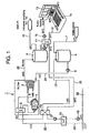
- FIG.1 is an overall system diagram of the first embodiment of the invention
- FIGS. 2-5 are overall system configuration of the second embodiment showing flow diagrams varying in accordance with operation modes
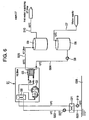
- FIG. 6 is a basic system configuration (example 1 for comparison) considered in the process to arrive at the present invention
- FIG. 7 is another basic system configuration (example 2 for comparison) considered in the process to arrive at the present invention.
- FIG.6 is a basic system configuration (example 1 for comparison) considered in the process to arrive at the present invention, by which it is envisioned to supply a heat source to hot water supplying equipment by a CO 2 heat pump.
- reference numeral 01 is a heat pump using CO 2 refrigerant, including a compressor 02, a gas cooler 03, an expansion valve 04, and an evaporator 05.
- Reference numeral 06 is a low temperature water tank to which low temperature water(city water, for example) of 10°C is supplied through a water supply line 07. The water stored in the tank 06 is supplied by means of a pump 08 to the gas cooler 03 through a pipe line 024, heated there to 65°C, and sent to a high temperature water tank 09 through a pipe line 025 to be stored therein.
- Reference numeral 026 indicates river water, sewage water, or waste water of temperature of 15°C. This riverwater, etc. 026 is introduced to aheat recovering heat exchanger 021, exchanges heat with brine (water) circulating in a circulation line 022 connecting the evaporator 05 of the heat pump 01 and the heat exchanger 021 for heating the brine.
- the brine circulating in the circulation line 022 is heated in the heat exchanger 021 from 5°C to 10°C and returns to the evaporator 05 to supply latent heat of vaporization for CO 2 refrigerant to be evaporated.
- the heat of river water, etc. is used as a heat source for supplying heat to evaporate the refrigerant in the evaporator 05 of the CO 2 heat pump 1.
- Coefficient of performance (COP) of 4.07 is attained with this system. Although high coefficient of performance can be achieved with this system by supplying low temperature water of 10°C to the gas cooler 03 and generating high temperature water of 65°C in the gas cooler 03, the system is applicable only to supply hot water to hot water supplying equipment, thus its application is restricted.
- FIG.7 is anther basic system configuration (example 2 for comparison) considered in the process to arrive at the present invention, by which it is envisioned to supply a heat source to an air conditioner for space heating in winter by a CO 2 heat pump. Comparing FIG. 7 with FIG. 6 , it is understood that in the system of FIG.7 , the pipe line 010 of FIG. 1 for supplying high temperature water to hot water supplying equipment is eliminated, instead a heat source is supplied to a heat waster, or radiator 013 constituting a space heating equipment and a heating floor panel 014 constituting a floor heating equipment.
- the high temperature water of 65°C stored in the high temperature water tank 09 is sent to a water-water heat exchanger 011 by a pump 015.
- a brine circulation line 012 passes through the water-water heat exchanger 011, the brine (water) being circulated in the circulation line 012 by means of a pump 016 between the radiator 013 and the heating floor panel 014 connected in series with the radiator 013 downstream thereof, and the brine exchanges heat in the heat exchanger 011 with the high temperature water to be heated from 30°C to 65°C and introduced to the radiator 013 to heat indoor space.
- the water decreased in temperature to 45°C is introduced to the heating floor panel 014 embedded in the room floor to perform floor heating.
- the brine decreased in temperature to 30°C after performing floor heating returns to the water-water heat exchanger 011.
- the hot water decreased in temperature to 35°C by heat exchange with the brine circulating in the circulation line 012 is too high in temperature to be returned to the low temperature water tank 06 as low temperature water, so it is introduced to a heat source water heat exchanger 018 through a pipe line 017.
- Said high temperature water of 35°C is cooled to 10°C by heat exchange with the brine circulating in the circulation line 022 in the heat source water heat exchanger 018 and returns to the low temperature water tank 06 through a pipe line 020.
- the river water, etc. 026 thus heated by said water of 35°C flowed out from the water-water heat exchanger 011 is introduced to the heat exchanger 021 to heat the brine circulating in the circulation line 022 connecting the evaporator 05, heat exchanger 021, and heat source water heat exchanger 018.
- the river water, etc. 026 after heating the brine returns back to the river, sewerage, etc., on the other hand, the brine circulating in the circulation line 022 is heated to be adjusted in temperature to 11°C in the heat exchanger 021 and returns to the evaporator 05 to supply latent heat of vaporization of the CO 2 refrigerant to evaporate it.
- the brine adjusted in heat quantity thereof in the heat exchanger 018 for heating heat source water and the heat exchanger 021 for recovering heat is used as a heat source for supplying latent heat of vaporization of the refrigerant to the refrigerant in the evaporator 05 of the CO 2 heat pump 1.
- the present invention was made on the basis of these basic system configurations and arrived at a system which can supply a heat source to hot water supplying equipment, air conditioning equipment, and others independently simultaneously or selectively. Examples of embodiment will be described hereunder.
- FIG.1 is a CO 2 heat pump system including a hot water equipment and a space heating equipment to supply a heat source to the equipments in winter.
- reference numeral 1 is a CO 2 heat pump comprised of a compressor 2, a gas cooler 3, an expansion valve 4, and an evaporator 5, using CO 2 as a refrigerant.
- Reference numeral 6 is a low temperature water tank to which low temperature water (city water, for example) of 10°C is supplied through a water supply line 7. The water stored in the tank 6 is supplied by means of a pump 8 to the gas cooler 3 through a pipe line 24, heated there to 65°C, and sent to a high temperature water tank 9 through a pipe line 25 to be stored therein.
- the high temperature water of 65°C stored in the high temperature water tank 9 is sent to hot water supplying equipment (not shown in the drawing) and at the same time sent by a pump 15 to a water-water heat exchanger 11.
- a brine circulation line 12 passes through the water-water heat exchanger 11, the brine(water) being circulated by means of a pump 16 in the circulation line 12 between a heat waster, or radiator 13 and the heating floor panel 14, and the brine exchanges heat in the heat exchanger 11 with the high temperature water to be heated from 30°C to 60°C and is introduced to the radiator 13 to heat indoor space.
- the water decreased in temperature to 50°C is introduced to the heating floor panel 14 embedded in the room floor to perform floor heating.
- the brine decreased in temperature to 30°C after performing floor heating returns to the water-water heat exchanger 11.
- the hot water decreased in temperature of 35°C by heat exchange with the brine circulating in the circulation line 12 is too high in temperature to be returned to the low temperature water tank 6 as low temperature water, so it is introduced to a heat source water heat exchanger 18 through a pipe line 17.
- Said high temperature water of 35°C is cooled to 10°C by heat exchange with the brine circulating in the circulation line 22 in the heat source water heat exchanger 18 and returns to the low temperature water tank 6 through a pipe line 20.
- the brine circulating in the circulation line 22 is heated in the heat exchanger 21 from 6°C to 11°C and returns to the evaporator 5 to be used as a heat source for evaporating the refrigerant.
- low temperature water is maintained at 10°C
- high temperature water is maintained at 65°C
- coefficient of performance of 4.14 can be maintained.
- hot water of 65°C heated in the gas cooler 3 can be supplied as a heat source for hot water supplying equipment and space heating equipment, the temperature of the water returned to the low temperature tank 6 can be fallen by heat exchange in the outside heating system or by heat exchange with waste water, etc. and reduction in coefficient of performance of the CO 2 heat pump 1 can be prevented.
- the brine (water) circulating in the circulation line 22 passing through the evaporator 5 of the heat pump 1 is heated by the hot water fallen in temperature in the water-water heat exchanger 11, by this the heat source side temperature of the evaporator 5 is raised and coefficient of performance of the heat pump 1 is increased.
- a CO 2 heat pump 31 performs heat source supply by way of a secondary side system unit 30, through which supplying of hot water or cool water to equipment A-E such as hot water supplying, space heating, floor heating, snow melting, and space cooling equipment is performed, and also is performed heat exchange between the refrigerant and/or hot water returning from the heating equipment and a heat receiving source F(source to be heated) or heat giving source G(source from which heat is withdrawn).
- equipment A-E such as hot water supplying, space heating, floor heating, snow melting, and space cooling equipment is performed, and also is performed heat exchange between the refrigerant and/or hot water returning from the heating equipment and a heat receiving source F(source to be heated) or heat giving source G(source from which heat is withdrawn).
- reference numeral 34 is a low temperature water tank to supply low temperature water to a gas cooler 32 of the heat pump 1
- 35 is a high temperature water tank for storing high temperature water heated to 35°C in the gas cooler 32.
- Reference numerals 36-41 are heat exchangers for allowing heat exchange between the hot or cool water flowing in the system 30 and the brine(water)flowing in the equipment A-E, and heat source fluid G, F found outside the system.
- Reference numerals 42-45, 66, and 67 are pumps provided in the system 30 for each corresponding piping.
- Reference numeral 51 is a communicating tube connecting the low temperature tank 34 with the high temperature tank 35, the open/close valve 51a opens or closes the passage of the communication tube 51. The open/close vale 51a is opened when storing hot water by nighttime operation.
- Reference numeral 52 is a water supply line for supplying low temperature water to the low temperature water tank 34, 53 is a hot water supply line for supplying the hot water of 65°C stored in the high temperature water tank 35 to the hot water supplying equipment A.
- FIG.2 shows the flow of water or brine when supplying hot water to hot water supplying equipment year-round.
- low temperature water of 10°C is supplied to the gas cooler 32 of the CO 2 heat pump 31 from the low water tank 34 by means of a pump 66 through a pipe line 54, the water is heated in the gas cooler 32 to a temperature of 65°C and this high temperature water is introduced into the high temperature water tank 35.
- the high temperature water is supplied to the hot water supplying equipment A through the pipe line 53.
- brine (water) circulation is formed in pipe lines 56 and 57 connecting between a heat exchanger 41 and an evaporator 33 of the CO 2 heat pump 31 by switching three-way valves 46 and 47.
- the heat receiving source F and heat giving source G correspond, for example, to river water, sewage water, waste water, etc. 26 of the first embodiment, and the heat exchanger 40 corresponds to the sewage water heat exchanger 18 and the heat exchanger 41 to the heat recovering heat exchanger 21.
- the brine(water) circulating in the circulation line formed between the evaporator 33 and heat exchanger 41 by the pipe lines 56 and 57 is heated in the heat exchanger 41, by this refrigerant passing through the evaporator 41 is supplied with heat to raise the heat source side temperature of the evaporator 33 and coefficient of performance of the heat pump 31 is increased.
- the open/close valve 51a of the communicating tube 51 connecting the high temperature water tank 35 and low temperature water tank 34 is opened to form a circulation line to allow water to flow from the lower temperature water tank 35 through the gas cooler 33 and high temperature water tank 35 to return to the low temperature tank 34 so that high temperature water is stored not only in the high temperature water tank 35 but also in the low temperature water tank and the system is operated continuously in the night. By this, storage amount of hot water can be increased.
- FIG.3 shows the flow of water or brine when performing hot water supplying and space heating in summer.
- low temperature water of 10°C is supplied from the low temperature tank 34 to the gas cooler 32 through the pipe line 54, the water is heated in the gas cooler 32 to high temperature of 65°C, this high temperature water is introduced to the high temperature water tank 35 through the pipe line 55 to be supplied to the hot water supplying equipment A through the pipe line 53 as a heat source.
- This is the same as is in the case of FIG.2 .
- low temperature water is supplied to the evaporator 33 of the heat pump 31 by means of the pump 44 through the pipe line 56, the water is cooled in the evaporator 33 and returns to the low temperature water tank 34.
- the cold water stored in the low temperature water tank 34 is supplied to a heat exchanger 39 by means of the pump 43 through a pipe line 56 and cools the brine of the space cooling equipment E, then returns to the low temperature water tank 34 through a pipe line 59.
- the hot water in the high temperature water tank 35 is introduced to the heat exchanger 40 through a pipe line 60, the heat exchanger 36, a pipe line 61, the heat exchanger 37, and a pipe line 62 by means of the pump 42.
- the hot water dissipates its heat to the heat receiving source F such as, for example, river water, sewage water, waste water, etc. to become low temperature water and returns to the low temperature water tank 34 through a pipe line 63.
- FIG.4 shows the flow of water or brine when performing hot water supplying, space heating, and floor heating in winter.
- hot water supplying is done as is in the case of FIG.2 and FIG.3 .
- high temperature water is supplied from the high temperature water tank 35 to the heat exchanger 36 through the pipe line 60 by means of the pump 42 to heat the brine of the space heating equipment B. Then the water is introduced to the heat exchanger 37 through the pipe line 61 to supply heat to the heating medium of floor heating equipment C, and then introduced to the heat exchanger 40 through the pipe line 62.
- the water introduced in the heat exchanger 40 and dissipates its heat there to a heat receiving source such as for example river water, sewage water, waste water, etc. to be cooled returns to the low temperature water tank 34.
- a heat receiving source such as for example river water, sewage water, waste water, etc. to be cooled.
- the hot water is first introduced to the heat exchanger 36 for the space cooling equipment B and then introduced to the heat exchanger 37 for the floor heating equipment C, the hot water first uses its heat for space heating to be reduced in temperature and then the water reduced in temperature uses its heat for floor heating, so hot water of a temperature appropriate for each of the space heating and floor heating respectively can be supplied.
- coefficient of performance of the heat pump is maintained high and high efficiency of the heat pump system is achieved.
- coefficient of performance of the heat pump 31 can be increased.
- FIG.5 shows the flow of water or brine when performing hot water supplying, space heating, floor heating, and snow melting in winter.
- hot water supply is done as is in the case of FIG. 2 and FIG. 3 .
- high temperature water is supplied from the high temperature tank 35 to heat exchanger 36 through the pipe line 60 by means of the pump 42 to supply heat to the brine of the space heating equipment B.
- the hot water is supplied sequentially to the heat exchanger 37 through the pipe line 61 and to the heat exchanger 38 through the pipe line 62 and 64 for supplying heat to the brine of the floor heating equipment B and the brine of the snow melting equipment D respectively.
- the water flowing out from the heat exchanger 38 after supplying heat to the brine of the snow melting equipment D is introduced to the low temperature water tank 34.
- withdrawing of heat is done only from the heat receiving source G.
- the hot water dissipates heat sequentially in each heat exchanger, so hot water is introduced to each heat exchanger at appropriate temperatures, for example, at 65°C at the entrance to the heat exchanger 36 for the space heating equipment B, at 50°C at the entrance to the heat exchanger 37 for the floor heating equipment C, and at 30°C at the entrance to the heat exchanger 38 for the floor heating equipment D.
- a heat pump system having all-round functions can be realized which performs hot water supplying and space cooling in summer and hot water supplying, space heating, and snow melting in winter.
- the temperature of the water supplied to the condenser(gas cooler) of the heat pump is always kept low, and particularly in winter by raising heat source side temperature in the evaporator by using outside heat source and part of the heat obtained by the heat pump, coefficient of performance of the heat pump is increased and a highly efficient heat pump system can be realized.
- a plurality of high temperature water tanks 35 or a plurality of low temperature water tanks 34 are provided in correspondence with the amount of heat supply necessary for hot water supply and air conditioning and so on.
- system of the invention can be applicable to the case the evaporator 33 is replaced by an air-to-refrigerant heat exchanger.
- the inlet temperature of the cooling water to the gas cooler of the heat pump is maintained lower than a certain temperature and the heat source side temperature of the evaporator of the heat pump is increased so that not only supply of hot water but also supply of heating medium or cooling medium to air conditioning or other equipment can be performed efficiently and effectively.
Landscapes
- Engineering & Computer Science (AREA)
- Physics & Mathematics (AREA)
- Thermal Sciences (AREA)
- Chemical & Material Sciences (AREA)
- Combustion & Propulsion (AREA)
- Mechanical Engineering (AREA)
- General Engineering & Computer Science (AREA)
- Water Supply & Treatment (AREA)
- Steam Or Hot-Water Central Heating Systems (AREA)
- Other Air-Conditioning Systems (AREA)
- Heat-Pump Type And Storage Water Heaters (AREA)
Claims (7)
- Warmwasserversorgungs- und Luftklimatisierungssystem, bei dem eine CO2-Wärmepumpe (1) verwendet wird, welche einen Kompressor (2), einen Gaskühler (3), eine Druckverminderungseinrichtung (4) und eine Verdampfungseinrichtung (5) beinhaltet, welche aufeinanderfolgend verbunden sind, für das Zuführen einer Wärmequelle zu einer Warmwasserversorgungseinrichtung und einer Luftklimatisierungseinrichtung durch unabhängige Rohrleitungen, umfassend:einen Hochtemperaturwasserbehälter (9) zum Aufbewahren von Wasser mit hoher Temperatur, welches in dem Gaskühler erhitzt wurde,gekennzeichnet durch
einen Niedrigtemperaturwasserbehälter (6) zum Aufbewahren von Wasser mit niedriger Temperatur,
Rohrleitung (10) für die Zufuhr des in dem Hochtemperaturwasserbehälter aufbewahrten Wassers mit hoher Temperatur als Wärmequelle zu der Warmwasserversorgungseinrichtung und einer Zimmererwärmungseinrichtung (13, 14),
einen ersten Wärmetauscher (21), worin Salzlösung, welche latente Verdampfungswärme des CO2-Kühlmittets dem Kühlmittel in dem Verdampfer zuführt, Wärme mit einem wärmegebenden Fluid (26) austauscht,
einen zweiten Wärmetauscher (18) stromaufwärts des ersten Wärmetauschers, um das Wasser mit hoher Temperatur, nachdem es als Wärmequelle für die Zimmererwärmungseinrichtung verwendet wurde, durch Wärmeaustausch mit dem Wärmeaufnahmefluid zu kühlen,
Rohrleitung (17) zum Einführen des in dem zweiten Wärmetauscher gekühlten Wassers in den Niedrigtemperaturwasserbehälter, und
eine Wasserzufuhreinrichtung zum Zuführen von Wasser mit niedriger Temperatur zu dem Niedrigtemperaturwasserbehälter;
wobei Wasser mit niedriger Temperatur von dem Niedrigtemperaturwasserbehälter zu dem Gaskühler geführt wird, um auf eine Temperatur gleich oder höher als 60°C erhitzt zu werden, um vermittels des Hochtemperaturwasserbehälters als Wärmequelle für die Warmwasserversorgungseinrichtung und Zimmererwärmungseinrichtung zugeführt zu werden. - Warmwasserversorgungs- und Luftklimatisierungssystem nach Anspruch 1,
wobei das System derart aufgebaut ist, dass die Wärme des wärmeliefernden Fluids als Wärmequelle in dem Verdampfer (5) verwendet wird, indem Wärme von dem wärmeliefernden Fluid in dem ersten Wärmetauscher (21) abgezogen wird, wenn das Wasser hoher Temperatur als Wärmequelle für die Warmwasserversorgungseinrichtung zugeführt wird. - Warmwasserversorgungs- und Luftklimatisierungssystem nach Anspruch 1,
wobei das System derart aufgebaut ist, dass das Wasser mit hoher Temperatur nach dessen Verwendung für die Wärmequelle für die Raumerwärmungseinrichtung (13, 14) und nach Temperaturverminderung in dem zweiten Wärmetauscher (18) auf eine Temperatur unterhalb Umgebungstemperatur gekühlt wird, um in den Niedrigtemperaturwasserbehälter (6) eingeführt zu werden, und die Wärme des wärmeliefernden Fluids als Wärmequelle in dem Verdampfer (5) verwendet wird, indem in dem ersten Wärmetauscher Wärme aus dem wärmeliefernden Fluid abgezogen wird, wenn das Wasser mit hoher Temperatur als Wärmequelle für die Warmwasserversorgungseinrichtung zugeführt wird. - Warmwasserversorgungs- und Luftklimatisierungssystem nach Anspruch 3,
worin das System derart aufgebaut ist, dass das Wasser mit hoher Temperatur, welches als Wärmequelle für die Zimmererwärmungseinrichtung, einschließlich einer Raumerwärmungseinrichtung (13) und einer Bodenerwärmungseinrichung (14), verwendet wird, nacheinander zunächst als Wärmequelle für die Raumerwärmungseinrichtung und dann als Wärmequelle für die Bodenerwärmungseinrichtung fließt, und das Wasser nach Verwendung für die Bodenerwärmungseinrichtung in dem zweiten Wärmetauscher (18) gekühlt wird, um zu dem Niedrigtemperaturwasserbehälter (6) zurückgeführt zu werden, so dass das Wasser mit hoher Temperatur an der Raumerwärmungseinrichtungsseite Wärme verteilt und dessen Temperatur vermindert wird, und dann weiter an der Bodenerwärmungseinrichtungsseite Wärme verteilt. - Warmwasserversorgungs- und Luftklimatisierungssystem nach Anspruch 1,
worin Rohrleitung (58) vorgesehen ist, um das in dem Niedrigtemperaturwasserbehälter (6, 34) aufbewahrte Wasser als Kühlmittel zu Kühleinrichtung (E) zu überführen. - Warmwasserversorgungs- und Luftklimatisierungssystem nach Anspruch 1,
worin das System derart aufgebaut ist, dass der Hochtemperaturwasserbehälter (9, 35) und der Niedrigtemperaturwasserbehälter (6, 34) mittels einer Passage (51), welche geöffnet oder geschlossen werden kann, in Verbindung stehen, und beide Behälter durch Öffnen der Passage verbunden werden, wenn ein Nachtbetrieb durchgeführt wird, um Wasser mit hoher Temperatur so aufzubewahren, dass das Wasser mit hoher Temperatur in dem Niedrigtemperaturwasserbehälter und in dem Hochtemperaturwasserbehälter gelagert wird. - Warmwasserversorgungs- und Luftklimatisierungssystem nach Anspruch 1,
worin das System derart aufgebaut ist, dass Rohrleitungen (60, 61, 62, 64), um zu ermöglichen, dass das Wasser mit hoher Temperatur fließt, um als Wärmequelle nacheinander für die Raumerwärmungseinrichtung (13, B), die Bodenerwärmungseinrichtung (14, C) und eine Schneeschmelzeinrichtung (D) verwendet zu werden, sowie eine Rohrleitung (65) zum Einführen des Wassers nach dessen Verwendung als Wärmequelle für die Schneeschmelzeinrichtung in den Niedrigtemperaturwasserbehälter (6, 34) vorgesehen sind,
wobei das Wasser mit hoher Temperatur an der Zimmererwärmungseinrichtungsseite, einschließlich der Raumerwärmungs- und Bodenerwärmungseinrichtung, Wärme verteilt und bezüglich der Temperatur vermindert wird, oder nur an der Raumerwärmungseinrichtungsseite, und anschließend Wärme weiter an der Schneeschmelzeinrichtungsseite verteilt und die Temperatur unterhalb Umgebungstemperatur vermindert wird, um zum Niedrigtemperaturwasserbehälter zurückgeführt zu werden.
Applications Claiming Priority (2)
| Application Number | Priority Date | Filing Date | Title |
|---|---|---|---|
| US62931104P | 2004-11-19 | 2004-11-19 | |
| PCT/JP2005/021749 WO2006054804A1 (en) | 2004-11-19 | 2005-11-21 | Hot water supply and air conditioning system using co2 heat pump |
Publications (2)
| Publication Number | Publication Date |
|---|---|
| EP1815188A1 EP1815188A1 (de) | 2007-08-08 |
| EP1815188B1 true EP1815188B1 (de) | 2013-01-09 |
Family
ID=35788131
Family Applications (1)
| Application Number | Title | Priority Date | Filing Date |
|---|---|---|---|
| EP05809377A Expired - Lifetime EP1815188B1 (de) | 2004-11-19 | 2005-11-21 | Eine co2-wärmepumpe verwendendes heisswasserversorgungs- und luftklimatisierungssystem |
Country Status (6)
| Country | Link |
|---|---|
| US (1) | US8151586B2 (de) |
| EP (1) | EP1815188B1 (de) |
| CA (1) | CA2586676C (de) |
| ES (1) | ES2401798T3 (de) |
| NO (1) | NO20072835L (de) |
| WO (1) | WO2006054804A1 (de) |
Cited By (1)
| Publication number | Priority date | Publication date | Assignee | Title |
|---|---|---|---|---|
| CN103994486B (zh) * | 2014-05-26 | 2016-08-24 | 北京建筑大学 | 燃气锅炉大温差高效供热系统 |
Families Citing this family (11)
| Publication number | Priority date | Publication date | Assignee | Title |
|---|---|---|---|---|
| SG127726A1 (en) * | 2004-04-27 | 2006-12-29 | Tay Cher Seng | The non-intrusive and extended use of water reservoirs in buildings as thermal storage for heating, ventilation and air conditioning systems |
| JP5502410B2 (ja) * | 2009-01-30 | 2014-05-28 | パナソニック株式会社 | 液体循環式暖房システム |
| JP5470374B2 (ja) * | 2009-04-13 | 2014-04-16 | パナソニック株式会社 | ヒートポンプ式暖房装置 |
| US8385729B2 (en) | 2009-09-08 | 2013-02-26 | Rheem Manufacturing Company | Heat pump water heater and associated control system |
| ES2657243T3 (es) | 2009-09-29 | 2018-03-02 | Carrier Corporation | Sistema y procedimiento para mantener la temperatura del aire dentro del sistema CVAA de un edificio |
| SE539398C2 (sv) | 2014-11-10 | 2017-09-12 | Energy Machines S A | Värmeanläggning innefattande värmepump med växelvis anslutbara ackumulatortankar |
| US20180187927A1 (en) * | 2017-01-03 | 2018-07-05 | Heatcraft Refrigeration Products Llc | System and method for reusing waste heat of a transcritical refrigeration system |
| US11493276B2 (en) * | 2019-04-29 | 2022-11-08 | Noventa Energy Partners Inc. | Feed water supplementary thermal exchange apparatus, system and method |
| WO2020220107A1 (en) * | 2019-04-30 | 2020-11-05 | Noventa Energy Partners | Feed water supplementary thermal exchange apparatus, system and method |
| WO2022023085A1 (en) * | 2020-07-28 | 2022-02-03 | Energy Services Limited | An energy system for supply of hot water |
| CN118532823B (zh) * | 2024-06-26 | 2026-04-24 | 中铁第一勘察设计院集团有限公司 | 太阳能富集区孤岛式铁路建筑群近零碳供能系统及其方法 |
Family Cites Families (9)
| Publication number | Priority date | Publication date | Assignee | Title |
|---|---|---|---|---|
| US4012920A (en) * | 1976-02-18 | 1977-03-22 | Westinghouse Electric Corporation | Heating and cooling system with heat pump and storage |
| US4257239A (en) * | 1979-01-05 | 1981-03-24 | Partin James R | Earth coil heating and cooling system |
| FR2451558A1 (fr) * | 1979-03-16 | 1980-10-10 | Satam Brandt Froid | Echangeur thermique pour pompe a chaleur, pompe a chaleur equipee d'un tel echangeur et installation de chauffage fonctionnant au moyen d'une telle pompe |
| EP0431491A1 (de) * | 1989-12-06 | 1991-06-12 | Kabushiki Kaisha Toshiba | Wärmepumpenartiges Heizgerät und Verfahren zur Steuerung dieses Gerätes |
| US5727396A (en) * | 1995-12-15 | 1998-03-17 | Gas Research Institute | Method and apparatus for cooling a prime mover for a gas-engine driven heat pump |
| KR100720165B1 (ko) * | 1999-05-20 | 2007-05-18 | 사이엔스 가부시기가이샤 | 냉동 사이클로 된 가열장치 |
| JP3815611B2 (ja) | 2001-12-27 | 2006-08-30 | 三洋電機株式会社 | ヒートポンプ給湯機 |
| DE20216324U1 (de) * | 2002-06-14 | 2003-03-13 | Adolph, Ulrich, Dr.-Ing., 04159 Leipzig | Wärmepumpe mit Kühlfunktion |
| CN1322286C (zh) * | 2002-12-13 | 2007-06-20 | 东京电力株式会社 | 使用气体水化物的热泵 |
-
2005
- 2005-11-21 US US11/719,480 patent/US8151586B2/en not_active Expired - Fee Related
- 2005-11-21 EP EP05809377A patent/EP1815188B1/de not_active Expired - Lifetime
- 2005-11-21 ES ES05809377T patent/ES2401798T3/es not_active Expired - Lifetime
- 2005-11-21 CA CA2586676A patent/CA2586676C/en not_active Expired - Fee Related
- 2005-11-21 WO PCT/JP2005/021749 patent/WO2006054804A1/en not_active Ceased
-
2007
- 2007-06-04 NO NO20072835A patent/NO20072835L/no not_active Application Discontinuation
Cited By (1)
| Publication number | Priority date | Publication date | Assignee | Title |
|---|---|---|---|---|
| CN103994486B (zh) * | 2014-05-26 | 2016-08-24 | 北京建筑大学 | 燃气锅炉大温差高效供热系统 |
Also Published As
| Publication number | Publication date |
|---|---|
| US8151586B2 (en) | 2012-04-10 |
| NO20072835L (no) | 2007-08-06 |
| US20090145149A1 (en) | 2009-06-11 |
| ES2401798T3 (es) | 2013-04-24 |
| WO2006054804A1 (en) | 2006-05-26 |
| EP1815188A1 (de) | 2007-08-08 |
| CA2586676A1 (en) | 2006-05-26 |
| CA2586676C (en) | 2013-03-12 |
Similar Documents
| Publication | Publication Date | Title |
|---|---|---|
| CN100501253C (zh) | 复合制冷采暖系统 | |
| JP5327308B2 (ja) | 給湯空調システム | |
| JP5373964B2 (ja) | 空調給湯システム | |
| JP4298990B2 (ja) | 二酸化炭素を冷媒として用いた冷凍装置 | |
| KR101864636B1 (ko) | 폐열회수형 하이브리드 히트펌프시스템 | |
| KR100998483B1 (ko) | 지열히트펌프를 이용한 모듈멀티형 냉난방시스템 | |
| US8151586B2 (en) | Hot water supply and air conditioning system using CO2 heat pump | |
| JP2013083439A5 (de) | ||
| JP2013083439A (ja) | 給湯空調システム | |
| JP2001099514A (ja) | 蓄熱式空調冷凍装置 | |
| KR100877056B1 (ko) | 하이브리드 히트펌프 시스템 | |
| JP5333557B2 (ja) | 給湯空調システム | |
| JP2004251557A (ja) | 二酸化炭素を冷媒として用いた冷凍装置 | |
| CN216384419U (zh) | 四管制风冷冷热水机组 | |
| CN212566000U (zh) | 空调余热回收系统及空调系统 | |
| JPS6337856B2 (de) | ||
| JP4419475B2 (ja) | 暖房システム及び住宅 | |
| KR101339297B1 (ko) | 지열을 이용한 다기능 히트펌프시스템 | |
| CN114593478A (zh) | 空调系统及其控制方法、装置、存储介质 | |
| JP2009133541A (ja) | ヒートポンプシステム | |
| JP2006145098A (ja) | 蓄熱式空気調和装置 | |
| JP2015124908A (ja) | 給湯空調システム | |
| KR20100040489A (ko) | 하이브리드형 지열 냉온수 공급 시스템 | |
| JP2002061897A (ja) | 蓄熱式空気調和機 | |
| JP2004028576A (ja) | 空調冷凍装置 |
Legal Events
| Date | Code | Title | Description |
|---|---|---|---|
| PUAI | Public reference made under article 153(3) epc to a published international application that has entered the european phase |
Free format text: ORIGINAL CODE: 0009012 |
|
| 17P | Request for examination filed |
Effective date: 20070618 |
|
| AK | Designated contracting states |
Kind code of ref document: A1 Designated state(s): AT BE BG CH CY CZ DE DK EE ES FI FR GB GR HU IE IS IT LI LT LU LV MC NL PL PT RO SE SI SK TR |
|
| DAX | Request for extension of the european patent (deleted) | ||
| 17Q | First examination report despatched |
Effective date: 20100621 |
|
| GRAP | Despatch of communication of intention to grant a patent |
Free format text: ORIGINAL CODE: EPIDOSNIGR1 |
|
| GRAS | Grant fee paid |
Free format text: ORIGINAL CODE: EPIDOSNIGR3 |
|
| GRAA | (expected) grant |
Free format text: ORIGINAL CODE: 0009210 |
|
| AK | Designated contracting states |
Kind code of ref document: B1 Designated state(s): AT BE BG CH CY CZ DE DK EE ES FI FR GB GR HU IE IS IT LI LT LU LV MC NL PL PT RO SE SI SK TR |
|
| REG | Reference to a national code |
Ref country code: GB Ref legal event code: FG4D |
|
| REG | Reference to a national code |
Ref country code: CH Ref legal event code: EP Ref country code: AT Ref legal event code: REF Ref document number: 592973 Country of ref document: AT Kind code of ref document: T Effective date: 20130115 |
|
| REG | Reference to a national code |
Ref country code: IE Ref legal event code: FG4D |
|
| REG | Reference to a national code |
Ref country code: DE Ref legal event code: R096 Ref document number: 602005037861 Country of ref document: DE Effective date: 20130307 |
|
| REG | Reference to a national code |
Ref country code: ES Ref legal event code: FG2A Ref document number: 2401798 Country of ref document: ES Kind code of ref document: T3 Effective date: 20130424 |
|
| PG25 | Lapsed in a contracting state [announced via postgrant information from national office to epo] |
Ref country code: SI Free format text: LAPSE BECAUSE OF FAILURE TO SUBMIT A TRANSLATION OF THE DESCRIPTION OR TO PAY THE FEE WITHIN THE PRESCRIBED TIME-LIMIT Effective date: 20130109 |
|
| REG | Reference to a national code |
Ref country code: NL Ref legal event code: VDEP Effective date: 20130109 |
|
| REG | Reference to a national code |
Ref country code: AT Ref legal event code: MK05 Ref document number: 592973 Country of ref document: AT Kind code of ref document: T Effective date: 20130109 |
|
| REG | Reference to a national code |
Ref country code: LT Ref legal event code: MG4D |
|
| PG25 | Lapsed in a contracting state [announced via postgrant information from national office to epo] |
Ref country code: BE Free format text: LAPSE BECAUSE OF FAILURE TO SUBMIT A TRANSLATION OF THE DESCRIPTION OR TO PAY THE FEE WITHIN THE PRESCRIBED TIME-LIMIT Effective date: 20130109 Ref country code: IS Free format text: LAPSE BECAUSE OF FAILURE TO SUBMIT A TRANSLATION OF THE DESCRIPTION OR TO PAY THE FEE WITHIN THE PRESCRIBED TIME-LIMIT Effective date: 20130509 Ref country code: SE Free format text: LAPSE BECAUSE OF FAILURE TO SUBMIT A TRANSLATION OF THE DESCRIPTION OR TO PAY THE FEE WITHIN THE PRESCRIBED TIME-LIMIT Effective date: 20130109 Ref country code: LT Free format text: LAPSE BECAUSE OF FAILURE TO SUBMIT A TRANSLATION OF THE DESCRIPTION OR TO PAY THE FEE WITHIN THE PRESCRIBED TIME-LIMIT Effective date: 20130109 Ref country code: AT Free format text: LAPSE BECAUSE OF FAILURE TO SUBMIT A TRANSLATION OF THE DESCRIPTION OR TO PAY THE FEE WITHIN THE PRESCRIBED TIME-LIMIT Effective date: 20130109 Ref country code: BG Free format text: LAPSE BECAUSE OF FAILURE TO SUBMIT A TRANSLATION OF THE DESCRIPTION OR TO PAY THE FEE WITHIN THE PRESCRIBED TIME-LIMIT Effective date: 20130409 Ref country code: CY Free format text: LAPSE BECAUSE OF FAILURE TO SUBMIT A TRANSLATION OF THE DESCRIPTION OR TO PAY THE FEE WITHIN THE PRESCRIBED TIME-LIMIT Effective date: 20130109 |
|
| PG25 | Lapsed in a contracting state [announced via postgrant information from national office to epo] |
Ref country code: NL Free format text: LAPSE BECAUSE OF FAILURE TO SUBMIT A TRANSLATION OF THE DESCRIPTION OR TO PAY THE FEE WITHIN THE PRESCRIBED TIME-LIMIT Effective date: 20130109 Ref country code: PT Free format text: LAPSE BECAUSE OF FAILURE TO SUBMIT A TRANSLATION OF THE DESCRIPTION OR TO PAY THE FEE WITHIN THE PRESCRIBED TIME-LIMIT Effective date: 20130509 Ref country code: FI Free format text: LAPSE BECAUSE OF FAILURE TO SUBMIT A TRANSLATION OF THE DESCRIPTION OR TO PAY THE FEE WITHIN THE PRESCRIBED TIME-LIMIT Effective date: 20130109 Ref country code: PL Free format text: LAPSE BECAUSE OF FAILURE TO SUBMIT A TRANSLATION OF THE DESCRIPTION OR TO PAY THE FEE WITHIN THE PRESCRIBED TIME-LIMIT Effective date: 20130109 Ref country code: LV Free format text: LAPSE BECAUSE OF FAILURE TO SUBMIT A TRANSLATION OF THE DESCRIPTION OR TO PAY THE FEE WITHIN THE PRESCRIBED TIME-LIMIT Effective date: 20130109 Ref country code: GR Free format text: LAPSE BECAUSE OF FAILURE TO SUBMIT A TRANSLATION OF THE DESCRIPTION OR TO PAY THE FEE WITHIN THE PRESCRIBED TIME-LIMIT Effective date: 20130410 |
|
| PG25 | Lapsed in a contracting state [announced via postgrant information from national office to epo] |
Ref country code: SK Free format text: LAPSE BECAUSE OF FAILURE TO SUBMIT A TRANSLATION OF THE DESCRIPTION OR TO PAY THE FEE WITHIN THE PRESCRIBED TIME-LIMIT Effective date: 20130109 Ref country code: EE Free format text: LAPSE BECAUSE OF FAILURE TO SUBMIT A TRANSLATION OF THE DESCRIPTION OR TO PAY THE FEE WITHIN THE PRESCRIBED TIME-LIMIT Effective date: 20130109 Ref country code: RO Free format text: LAPSE BECAUSE OF FAILURE TO SUBMIT A TRANSLATION OF THE DESCRIPTION OR TO PAY THE FEE WITHIN THE PRESCRIBED TIME-LIMIT Effective date: 20130109 Ref country code: DK Free format text: LAPSE BECAUSE OF FAILURE TO SUBMIT A TRANSLATION OF THE DESCRIPTION OR TO PAY THE FEE WITHIN THE PRESCRIBED TIME-LIMIT Effective date: 20130109 Ref country code: CZ Free format text: LAPSE BECAUSE OF FAILURE TO SUBMIT A TRANSLATION OF THE DESCRIPTION OR TO PAY THE FEE WITHIN THE PRESCRIBED TIME-LIMIT Effective date: 20130109 |
|
| PLBE | No opposition filed within time limit |
Free format text: ORIGINAL CODE: 0009261 |
|
| STAA | Information on the status of an ep patent application or granted ep patent |
Free format text: STATUS: NO OPPOSITION FILED WITHIN TIME LIMIT |
|
| 26N | No opposition filed |
Effective date: 20131010 |
|
| REG | Reference to a national code |
Ref country code: DE Ref legal event code: R097 Ref document number: 602005037861 Country of ref document: DE Effective date: 20131010 |
|
| REG | Reference to a national code |
Ref country code: CH Ref legal event code: PL |
|
| PG25 | Lapsed in a contracting state [announced via postgrant information from national office to epo] |
Ref country code: MC Free format text: LAPSE BECAUSE OF FAILURE TO SUBMIT A TRANSLATION OF THE DESCRIPTION OR TO PAY THE FEE WITHIN THE PRESCRIBED TIME-LIMIT Effective date: 20130109 Ref country code: CH Free format text: LAPSE BECAUSE OF NON-PAYMENT OF DUE FEES Effective date: 20131130 Ref country code: LI Free format text: LAPSE BECAUSE OF NON-PAYMENT OF DUE FEES Effective date: 20131130 |
|
| REG | Reference to a national code |
Ref country code: IE Ref legal event code: MM4A |
|
| PG25 | Lapsed in a contracting state [announced via postgrant information from national office to epo] |
Ref country code: IT Free format text: LAPSE BECAUSE OF NON-PAYMENT OF DUE FEES Effective date: 20131121 |
|
| PG25 | Lapsed in a contracting state [announced via postgrant information from national office to epo] |
Ref country code: IE Free format text: LAPSE BECAUSE OF NON-PAYMENT OF DUE FEES Effective date: 20131121 |
|
| PG25 | Lapsed in a contracting state [announced via postgrant information from national office to epo] |
Ref country code: TR Free format text: LAPSE BECAUSE OF FAILURE TO SUBMIT A TRANSLATION OF THE DESCRIPTION OR TO PAY THE FEE WITHIN THE PRESCRIBED TIME-LIMIT Effective date: 20130109 |
|
| REG | Reference to a national code |
Ref country code: ES Ref legal event code: FD2A Effective date: 20150715 |
|
| PG25 | Lapsed in a contracting state [announced via postgrant information from national office to epo] |
Ref country code: ES Free format text: LAPSE BECAUSE OF NON-PAYMENT OF DUE FEES Effective date: 20131122 Ref country code: LU Free format text: LAPSE BECAUSE OF NON-PAYMENT OF DUE FEES Effective date: 20131121 Ref country code: HU Free format text: LAPSE BECAUSE OF FAILURE TO SUBMIT A TRANSLATION OF THE DESCRIPTION OR TO PAY THE FEE WITHIN THE PRESCRIBED TIME-LIMIT; INVALID AB INITIO Effective date: 20051121 |
|
| REG | Reference to a national code |
Ref country code: FR Ref legal event code: PLFP Year of fee payment: 11 |
|
| REG | Reference to a national code |
Ref country code: FR Ref legal event code: PLFP Year of fee payment: 12 |
|
| REG | Reference to a national code |
Ref country code: FR Ref legal event code: PLFP Year of fee payment: 13 |
|
| REG | Reference to a national code |
Ref country code: FR Ref legal event code: PLFP Year of fee payment: 14 |
|
| PGFP | Annual fee paid to national office [announced via postgrant information from national office to epo] |
Ref country code: DE Payment date: 20191105 Year of fee payment: 15 |
|
| PGFP | Annual fee paid to national office [announced via postgrant information from national office to epo] |
Ref country code: FR Payment date: 20191014 Year of fee payment: 15 |
|
| PGFP | Annual fee paid to national office [announced via postgrant information from national office to epo] |
Ref country code: GB Payment date: 20191122 Year of fee payment: 15 |
|
| REG | Reference to a national code |
Ref country code: DE Ref legal event code: R119 Ref document number: 602005037861 Country of ref document: DE |
|
| GBPC | Gb: european patent ceased through non-payment of renewal fee |
Effective date: 20201121 |
|
| PG25 | Lapsed in a contracting state [announced via postgrant information from national office to epo] |
Ref country code: FR Free format text: LAPSE BECAUSE OF NON-PAYMENT OF DUE FEES Effective date: 20201130 |
|
| PG25 | Lapsed in a contracting state [announced via postgrant information from national office to epo] |
Ref country code: DE Free format text: LAPSE BECAUSE OF NON-PAYMENT OF DUE FEES Effective date: 20210601 Ref country code: GB Free format text: LAPSE BECAUSE OF NON-PAYMENT OF DUE FEES Effective date: 20201121 |